

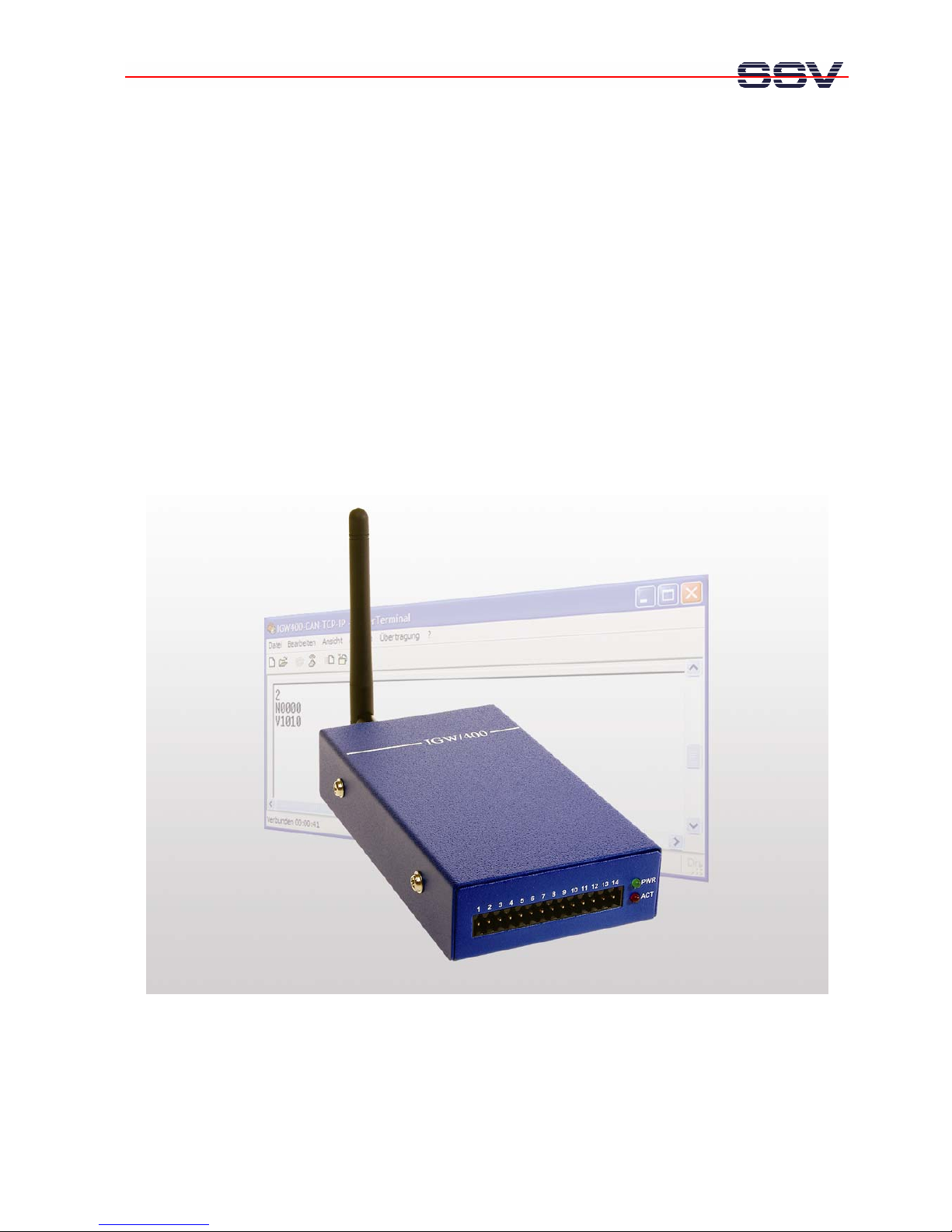
IGW/400-CA
N
WLAN Device Serve
r
Firmware Update
User Manual
SSV Embedded Systems
Heisterbergallee 72
D-30453 Hannover
Phone: +49 (0)511/40 000-0
Fax: +49 (0)511/40 000-40
E-mail: sales@ist1.de
Manual Revision: 1.0
Date: 2006-01-31
For further information regarding our products please visit us at www.ssv-embedded.de

IGW/400-CAN – Content
SSV EMBEDDED SYSTEMS
2
CONTENT
1 INTRODUCTION............................................................................................................... 3
1.1 Hardware Requirements............................................................................................................3
1.2 Software Requirements.............................................................................................................3
2 PREPARATIONS ..............................................................................................................4
2.1 Installing Philips LPC2000 Flash Utility..................................................................................4
2.2 Preparing IGW/400-CAN .........................................................................................................4
3 UPGRADING THE IGW/400-CAN FIRMWARE ................................................................ 7
3.1 Configure the Philips LPC2000 Flash Utility...........................................................................7
3.2 Power up the IGW/400-CAN....................................................................................................7
3.3 Test the Connection ..................................................................................................................8
3.4 Upload the new Firmware.........................................................................................................9
3.5 Complete the Firmware Upgrade............................................................................................10
CONTACT .............................................................................................................................11
DOCUMENT HISTORY ......................................................................................................... 11
COPYRIGHT .........................................................................................................................11

IGW/400-CAN – Introduction
SSV EMBEDDED SYSTEMS
3
1 INTRODUCTION
This document describes how to upgrade the firmware of the IGW/400-CAN. For further
information about the individual components of this product you may read the
IGW/400-CAN hardware reference and follow the links from our website at
http://www.ssv-comm.de.
Our website contains a lot of technical information, which will be updated in regular
periods.
1.1 Hardware Requirements
The following hardware is needed to upgrade the IGW/400-CAN:
• One PC with Windows 98 or higher
• One IGW/400-CAN
• One power supply cable
• One plug-in power supply (6 .. 30 V)
• One null modem cable
• One RS232 adapter cable
• One screw driver
• Two jumpers
1.2 Software Requirements
To upgrade the IGW/400-CAN firmware the Philips LPC2000 Flash Utility must be
installed on your Windows PC. You find this utility on your Starter Kit CD-ROM (rev.
1.2) in the directory CD-ROM:\isp-win32.
You can also search on the Philips website for a newer version of the flash utility. Enter
the URL http://www.semiconductors.philips.com in your browser and
search for “LPC2000 Flash Utility”.
IGW/400-CAN – Preparations
SSV EMBEDDED SYSTEMS
4
2 PREPARATIONS
2.1 Installing Philips LPC2000 Flash Utility
Copy the flash utility from the Starter Kit CD-ROM resp. download it from the Philips
website to your Windows PC (see chapter 1.2). Unzip the file and execute setup.exe.
Just follow the instructions during the installation. If the system asks to keep a newer
version of a certain file say YES.
2.2 Preparing IGW/400-CAN
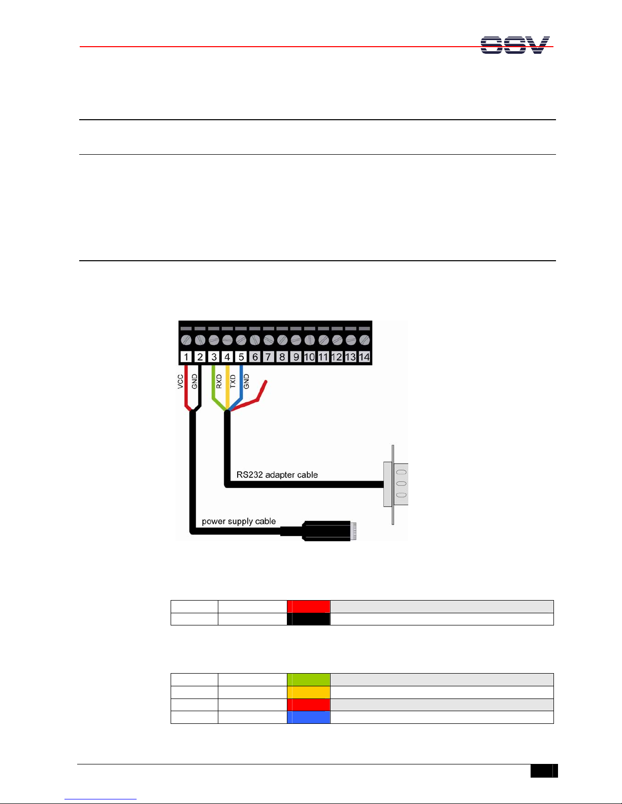
Connect the power supply cable as well as the RS232 adapter cable with the 14-pin
Environment Interface of the IGW/400-CAN like shown in the following figure. Use the
screw driver to fix the cables.
Figure 1: Pin assignment of plug-in connector
Pin Wire color Signal
1 red
VCC
2 black GND
Table 1: Pin assignment of power supply cable
Pin Wire color Signal
4 green
RXD
5 yellow TXD
7 red RTS (must not be connected)
9 blue GND
Table 2: Pin assignment of RS232 adapter cable

IGW/400-CAN – Preparations
SSV EMBEDDED SYSTEMS
5
Now connect the null modem cable with a free COM port of your Windows PC and the
RS232 adapter cable of the IGW/400-CAN like shown in the figure below.
Figure 2: Connecting Windows PC and IGW/400-CAN
Caution: DO NOT connect the plug-in power supply with the power supply cable yet!

IGW/400-CAN – Preparations
SSV EMBEDDED SYSTEMS
6
Open the case of the IGW/400-CAN carefully.
Set the ISP mode jumper (JP2) and the Watchdog disable jumper (Pins 9 and 10 on J2)
like shown in the following figure:
Figure 3: Setting the ISP mode jumper and the Watchdog disable jumper

IGW/400-CAN – Upgrading the IGW/400-CAN Firmware
SSV EMBEDDED SYSTEMS
7
3 UPGRADING THE IGW/400-CAN FIRMWARE
3.1 Configure the Philips LPC2000 Flash Utility
Start the Philips LPC2000 Flash Utility. You will see this window:
Figure 4: Start window of LPC2000 Flash Utility
Set the following parameters:
• Choose the COM port of your Windows PC
• Set the Baud Rate to 38400
• Choose the LPC2129 as device
• Set the XTAL frequency to 12000
3.2 Power up the IGW/400-CAN
Now connect the power supply cable with the plug-in power supply to start the
IGW/400-CAN.
Caution: DO NOT touch the boards or any other parts inside the IGW/400-CAN while it
is connected to the power supply!

IGW/400-CAN – Upgrading the IGW/400-CAN Firmware
SSV EMBEDDED SYSTEMS
8
3.3 Test the Connection
To test the connection between the IGW/400-CAN and your Windows PC click the
button “Read Device ID” of the Philips LPC2000 Flash Utility.
If you receive an error message, try to read the device ID a second time. If you still
receive an error message, please check the cable connections and the settings of the
Philips LPC2000 Flash Utility.
You will see the part ID and the boot loader ID in the corresponding fields as well as a
message in the status bar at the bottom of the window, if the readout was successful:
Figure 5: “Read Device ID” was successful

IGW/400-CAN – Upgrading the IGW/400-CAN Firmware
SSV EMBEDDED SYSTEMS
9
3.4 Upload the new Firmware
Click the button “…” (Filename) to choose the new firmware. The firmware file is called
igw400_scli_upgrade.hex and is located in the directory CD-ROM:\isp-win32 on the
Starter Kit CD-ROM.
Now click the button “Upload to Flash”. You will see the upload progress like shown in
the next figure:
Figure 6: Uploading the new firmware

IGW/400-CAN – Upgrading the IGW/400-CAN Firmware
SSV EMBEDDED SYSTEMS
10
3.5 Complete the Firmware Upgrade
After the successfully completed firmware upgrade you will see this window:
Figure 7: Firmware upgrade successfully completed
Please follow now these steps:
1. Exit the Philips LPC2000 Flash Utility.
2. Disconnect the power supply cable from the plug-in power supply.
3. Remove the jumpers on the IGW/400-CAN.
4. Close the case of the IGW/400-CAN.
That’s it! Now you can start the IGW/400-CAN again and work with the new firmware.

IGW/400-CAN – Contact
SSV EMBEDDED SYSTEMS
11
CONTACT
SSV Embedded Systems
Heisterbergallee 72
D-30453 Hannover / Germany
Phone: +49 (0)511/40 000-0
Fax: +49 (0)511/40 000-40
E-mail: sales@ist1.de
Internet: www.ssv-embedded.de
DOCUMENT HISTORY
Revision Date Remarks Name
1.0 2006-01-31 first version WBU
COPYRIGHT
The content of this document can change any time without announcement. There is taken
over no guarantee for the accuracy of the statements. The user assumes the entire risk as
to the accuracy and the use of this document. Information in this document is provided
‘as is’ without warranty of any kind. Some names within this document can be
trademarks of their respective holders.
© 2006 SSV EMBEDDED SYSTEMS. All rights reserved.
 Loading...