

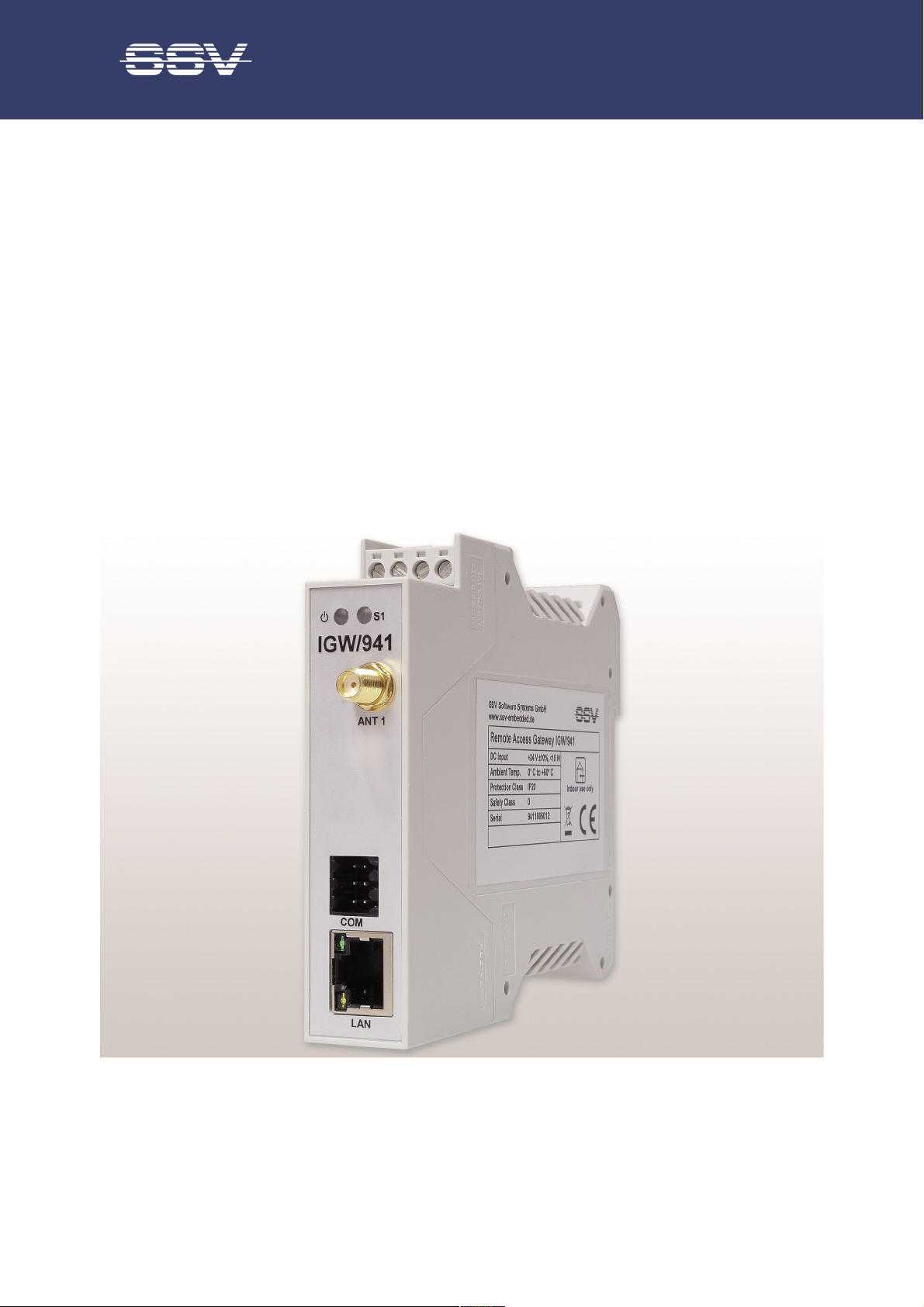
Remote Access Gateway IGW/941
with DNP/9535
Hardware Reference
SSV Software Systems GmbH
Dünenweg 5
D-30419 Hannover
Phone: +49 (0)511/40 000-0
Fax: +49 (0)511/40 000-40
Email: sales@ssv-embedded.de
Document Revision: 1.4
Date: 2019-07-03

Remote Access Gateway IGW/941 – Hardware Reference
2
CONTENT
1 INTRODUCTION ............................................................................................................... 3
1.1
1.2
1.3
Safety Guidelines ................................................................................................................... 3
Conventions ........................................................................................................................... 3
Features and Technical Data ................................................................................................. 4
2 OVERVIEW ....................................................................................................................... 5
3 PINOUTS .......................................................................................................................... 6
3.1
3.2
3.3
Ethernet Interface .................................................................................................................. 6
Screw Terminals ..................................................................................................................... 6
Service Port ............................................................................................................................ 7
4 SIM CARD ......................................................................................................................... 8
5 HELPFUL LITERATURE .................................................................................................. 9
CONTACT ............................................................................................................................... 9
DOCUMENT HISTORY ........................................................................................................... 9
D o c u m e n t R e vi s io n 1 . 4
3
1 INTRODUCTION
Convention
Usage
bold
Important terms and information
monospac
e Filenames, Pathnames, program code, command lines
This document describes the hardware components and the necessary cable connections of
the Remote Access Gateway IGW/941.
1.1 Safety Guidelines
Please read the following safety guidelines carefully! In case of property or personal
damage by not paying attention to this manual and/or by incorrect handling, we do not
assume liability. In such cases any warranty claim expires.
• The power supply should be in immediate proximity to the device.
• The power supply must provide a stable output voltage at 24 VDC ± 10%. The out-
put power should be at least 10 W.
• Please pay attention that the power cord or other cables are not squeezed or dam-
aged in any way when you set up the device.
Remote Access Gateway IGW/941 – Hardware Reference
• Do NOT turn on the power supply while connecting any cables, especially the pow-
er cables. This could cause damaged device components! First connect the cables
and THEN turn the power supply on.
• The installation of the device should be done only by qualified personnel.
• Discharge yourself electrostatic before you work with the device, e.g. by touching a
heater of metal, to avoid damages.
• Stay grounded while working with the device to avoid damage through electrostat-
ic discharge.
• The case of the device should be opened only by qualified personnel.
1.2 Conventions
Table 1: Conventions used in this document
D o c u m e n t R e vi s io n 1 . 4

Remote Access Gateway IGW/941 – Hardware Reference
4
Processor
Manufacturer / Type
Atmel ATSAM
-
A5D35
SoC
Clock speed
528 MHz
Memory
RAM
256 MB SDRAM
Flash
4 MB NOR memory
Storage media
1x internal microSD card holder
Interfaces
Ethernet
1x 10/100 Mbps (RJ45)
Serial I/Os
1x RS485 serial port (screw terminal)
COM (
Service
Port)
1x 6-pin connector
Antenna
1x SMA
male
connector for LTE antenna
Special Functions
Watchdog
1x Timer watch
dog (hardware
-
based, software
-
configurable)
SIM card
1x Mini
-
SIM card holder (accessible from the outside)
Wireless Module
Mobile radio standards
GSM/UMTS/HSPA+/LTE
Transfer rates
150 Mbps peak download, 50 Mbps pea
k upload
Frequency bands
LTE: 2600 MHz (B7), 2100 MHz (B1), 1800 MHz (B3),
Authentication
PAP, CHAP, CHAT, none
Supporte
d APNs
Telekom, Vodafone, 02, E
-
Plus, user
-
defined
Displays / Control Elements
LEDs
1x Power
Electrical Characteristics
Power supply
range
12 .. 2
7 VDC from external power supply
Power
consumption
< 15 W
Mechanical Characteristics
Protection class
IP20 industrial case for 35 mm DIN
-
rail mounting
Mass
< 150 g
Dimensions
112 mm x 100 mm x 22.5 mm
Operating temperature
0 .. 60 °C
Storage temperature
-40 .. 85 °C
Standards and Certifi
cations
EMC
CE,
EN 61000 6
-2, EN 61000 6
-4
Environmental
RoHS, WEEE
Vibration resistance
IEC 60721
-3-2 (classification of groups of environmental pa-
Corrosion protection
ISO 12944
-2 C2 for installation in control cabinets
1.3 Features and Technical Data
1x Power supervisor (hardware-based)
900 MHz (B8), 850 MHz (B5), 800 MHz (B20)
WCDMA: 2100 MHz (B1), 850 MHz (B5), 900 MHz (B8)
GSM/GPRS: Quad-band 850/900/1800/1900 MHz
1x System status (programmable)
2x LAN LED for Ethernet interface
standards
rameters and their severities - transportation and handling)
D o c u m e n t R e vi s io n 1 . 4

5
2 OVERVIEW
Remote Access Gateway IGW/941 – Hardware Reference
Figure 1: Overview Remote Access Gateway IGW/941
D o c u m e n t R e vi s io n 1 . 4

Remote Access Gateway IGW/941 – Hardware Reference
6
Pin Name
Function
TX+ 10/100 Mbps LAN, TX+
TX-
10/100 Mbps LAN, TX
-
RX+ 10/1
00 Mbps LAN, RX+
--- Bob-Smith Termination
--- Bob-Smith Termination
RX-
10/100 Mbps LAN, RX
-
--- Bob-Smith Termination
8
--- Bob-Smith Termination
LED Function
10/100BASE
-
T link/activity
Not Co
n
nected
Terminal
Function
A1 COM
2 Serial Port
: RS485 RX /TX+
A2 COM
2 Serial Port
:
RS485 RX /TX
-
A3 Vin 2
4 VDC ±10%
A4 Ground
3 PINOUTS
3.1 Ethernet Interface
1
2
3
4
5
6
7
Table 2: Pinout Ethernet interface
Green (left)
Yellow (right)
Table 3: Ethernet LED functions
3.2 Screw Terminals
Table 4: Pinout screw terminals
D o c u m e n t R e vi s io n 1 . 4

Remote Access Gateway IGW/941 – Hardware Reference
7
Pin Name
Function
RXD1
COM1
Serial Port: RS
232 RXD
TXD1
COM1
Serial Port: RS
232 T
XD
GND
Ground
RCM
COM1
Serial Port:
Remote Console Mode
CTS1
COM1
Serial Port: RS
232 CTS
RTS1
COM1
Serial Port: RS
232 RTS
Service Port
Sub-D Male Connector (DTE)
Pin 1 (RXD)
Pin 2 (RXD)
Pin 2 (TXD)
Pin 3 (TXD)
Pin 3 (GND)
Pin 5 (GND)
Pin 4 (RCM)
---
All other pins are not connected
.
3.3 Service Port
1
2
3
4
5
6
Table 5: Pinout service port
= Cable bridge
To create a serial connection between the IGW/941 and a PC an adapter cable and a null
modem cable are necessary.
The adapter cable is connected with the PC via the null modem cable like shown in fig. 2.
Table 6 shows which service port pins must be connected with the pins of a Sub-D male
connector (DTE, data terminal equipment) to build an adapter cable.
Table 6: Pinout adapter cable
Figure 2: Serial connection between IGW/941 and PC
D o c u m e n t R e vi s io n 1 . 4

Remote Access Gateway IGW/941 – Hardware Reference
8
4 SIM CARD
The internal SIM card of the IGW/941 can be changed through the slot on the backside.
To remove the SIM card just push it gently with a screw driver until you hear a soft "click".
The SIM card is ejected a few millimeters and can be pulled out easily.
Figure 3: Removing the SIM card
To insert the SIM card just push it by hand as deep as possible into the slot.
Please note:
Pay attention to the correct orientation of the SIM card like shown in fig. 4!
Then use a screw driver to push it gently further into the slot until you here a soft "click".
Figure 4: Inserting the SIM card
D o c u m e n t R e vi s io n 1 . 4

Remote Access Gateway IGW/941 – Hardware Reference
9
Revision
Date Remarks
Name
Review
nouncement. There is taken over no guaran-
accuracy and the use of
this document. Information in this document is provided ‘as is’ without warranty of any kind. Some names
5 HELPFUL LITERATURE
• DNP/9535 hardware reference
• SSV Web ConfigTool User Manual
CONTACT
SSV Software Systems GmbH
Dünenweg 5
D-30419 Hannover
Phone: +49 (0)511/40 000-0
Fax: +49 (0)511/40 000-40
E-mail: sales@ssv-embedded.de
Internet: www.ssv-embedded.de
Forum: www.ssv-comm.de/forum
DOCUMENT HISTORY
1.0 2018-02-14 First version WBU SSC
1.1 2018-04-04 Corrected the pinout of table 4 and table 5 WBU HNE
1.2 2018-10-08 Edited chapter 1.3, added adapter cable in chapter 3.3
1.3 2018-12-04 Updated features of “wireless module” in chapter 1.3 WBU SSC
1.4 2019-07-03 Updated table in chapter 1.3 WBU SSC
WBU HNE
The content of this document can change any time without an
tee for the accuracy of the statements. The user assumes the entire risk as to the
within this document can be trademarks of their respective holders.
© 2019 SSV SOFTWARE SYSTEMS GmbH. All rights reserved.
D o c u m e n t R e vi s io n 1 . 4
 Loading...