

Page 1
Modbus RTU/TCP/IoT Protocol Gateway
IOT600-TWX-TS
User Manual
V1.0 REV A
SST Automation
E-mail: SUPPORT@SSTCOMM.COM
WWW.SSTCOMM.COM
Page 2

WWW.SSTCOMM.COM
1
Catalog
1 Introduction................................................................................................................................................................2
1.1 About This Document.....................................................................................................................................2
1.2 Copyright information.................................................................................................................................... 2
1.3 Related Products............................................................................................................................................. 2
2 Product Overview...................................................................................................................................................... 3
2.1 Product Function.............................................................................................................................................3
2.2 Product Features............................................................................................................................................. 3
3 Hardware Description................................................................................................................................................5
3.1 Appearance......................................................................................................................................................5
3.2 Indicators.........................................................................................................................................................6
3.3 Configuration Switch......................................................................................................................................6
3.4 Interface.......................................................................................................................................................... 7
3.4.1 Power Interface....................................................................................................................................7
3.4.2 Ethernet Interface.................................................................................................................................8
3.4.3 Serial Interface.....................................................................................................................................8
4 Instructions of Configuration Software................................................................................................................... 11
4.1 Notes before Configuring............................................................................................................................. 11
4.2 Rapid Configuration......................................................................................................................................11
4.3 Search Equipment.........................................................................................................................................12
4.3.1 Search All Equipment in Ethernet..................................................................................................... 12
4.3.2 IP Search............................................................................................................................................ 12
4.4 Configuration................................................................................................................................................14
4.4.1 Configuring Ethernet Parameters...................................................................................................... 15
4.4.2 Configuring Modbus Serial Port Parameters.................................................................................... 16
4.4.3 Configuring Modbus TCP Master Parameters.................................................................................. 17
4.4.4 Configuring Modbus Command........................................................................................................18
4.4.5 Configuring Modbus TCP Slave Parameters.................................................................................... 21
4.5 Locate............................................................................................................................................................21
4.6 Remote Reset................................................................................................................................................ 22
4.7 Open/Save/Export EXCEL...........................................................................................................................23
4.8 Auto Assign Property Name/Download....................................................................................................... 26
4.9 New...............................................................................................................................................................27
5 Typical Application..................................................................................................................................................29
6 Installation................................................................................................................................................................30
6.1 Machine Dimension......................................................................................................................................30
6.2 Installation Method.......................................................................................................................................31
Page 3

WWW.SSTCOMM.COM
2
1 Introduction
1.1 About This Document
This document describes the parameters, use methods and considerations of IOT600-TWX-TS,providing a
detailed technical implementation guide for developers. Please read this manual carefully before using the
gateway.
1.2 Copyright information
The data and examples in this document cannot be copied without authorization.
is the registered trade mark of SST Automation.
1.3 Related Products
If you want to get more information about related products, please visit SSTCOMM website:
http://www.sstcomm.com or Call the technical support hotline: +1-626-569-7107.
Page 4

WWW.SSTCOMM.COM
3
2 Product Overview
Support connecting 15 Modbus slaves
Each serial port supports up to 100 Modbus commands
Support baud rate:1200, 2400, 4800, 9600, 19200, 38400, 57600 and 115200bps
Support 01H, 02H, 03H, 04H, 05H, 06H 0FH and 10H function codes
Support up to 100 Modbus commands and up to 36 Modbus TCP devices
Support 01H, 02H, 03H, 04H, 05H, 06H 0FH and 10H function codes
Support 01H, 02H, 03H, 04H, 05H, 06H 0FH and 10H function codes and up to 36 Modbus TCP master
Register supports int16, uint16, int32, int32 inverse, uint32, uint32 inverse, float, float inverse, double,
Support coil status block, input status block, hold register block and input register block, each block
2.1 Product Function
IOT600-TWX-TS is designed to get ThingWorx users connected to their Modbus RTU slave, Modbus TCP
slave and Modbus TCP Master devices with just a few minutes of configuration time. The gateway could be edge
gateways that securely connect industrial Modbus equipment over Ethernet networks to ThingWorx.
2.2 Product Features
[1] Support maximum number of properties:1000 (Encrypted communication:860);
[2] The communication mode adopts the WebSocket mode and support TLS encrypted transmission;
[3] Modbus RTU master
[4] Modbus TCP master
[5] Modbus TCP slave
double inverse, int64, int64 inverse, uint64, uint64 inverse
supports the maximum 1024 registers or bits
[6] Power supply: 24VDC (9V ~ 30V), 90mA (24VDC);
[7] Working temperature: -4℉~140℉(-20℃~60℃), relative humidity: 5% ~ 95% (non-condensing);
[8] External Dimensions (W*H*D): 1.57 in*4.92 in*4.33 in (40mm*125mm*110mm);
Page 5

WWW.SSTCOMM.COM
4
[9] Installation: 35mm rail;
[10] Protection class: IP20;
Page 6

WWW.SSTCOMM.COM
5
3 Hardware Description
serial port I indicators
Ethernet RJ45 interface
Configuration switch
Dual power interface
serial port II indicators
RS-485 serial port I
Modbus TCP indicators
RS-485 serial port II
3.1 Appearance
Page 7
WWW.SSTCOMM.COM
6
3.2 Indicators
Indicators
Status
Descriptions
ENS
Green on
IP address has not conflict
Red on
IP address has conflict
Blinking(Red)
DHCP,IP address conflict detection
Green on
Modbus TCP interface has data to
receive or send.
Blinking(Green)
Modbus TCP interface has not data to
receive or send.
SNS
Green on
Connect to the cloud platform
Blinking(Green)/Blinkin
g(Red)/Red on
Unconnected to the cloud platform
ENS (Orange) and SNS (Orange)
(Orange: Red and green light on at
the same time)
Simultaneously on
Start-up state
Blink alternately
Configuration mode or Retained mode
Blink alternately
(lasts 3 seconds)
Using locate function
serial port I TX
Blinking(Green)
serial port I is sending data
Close(Green)
serial port I isn't sending data.
serial port I RX
Blinking(Green)
serial port I is receiving data.
Close(Green)
serial port I isn't receiving data.
serial port II TX
Blinking(Green)
serial port II is sending data
Close(Green)
serial port II isn't sending data.
serial port II RX
Blinking(Green)
serial port II is receiving data.
Close(Green)
serial port II isn't receiving data.
Off
On 1 2
3.3 Configuration Switch
The DIP switch is located at the bottom of the gateway, bit 1 is mode bit and bit 2 is function bit.
Page 8

WWW.SSTCOMM.COM
7
Mode (bit 1)
Function (bit 2)
Description
Off
Off
Run mode, allowing reading and writing of configuration
Off
On
Run mode, forbidding reading and writing configuration
On
Off
Configuration mode, IP address is 192.168.0.10 (fixed),
On
On
Reserved
Notes:Restart IOT600-TWX-TS (power off and power on) or remote reset after resetting the
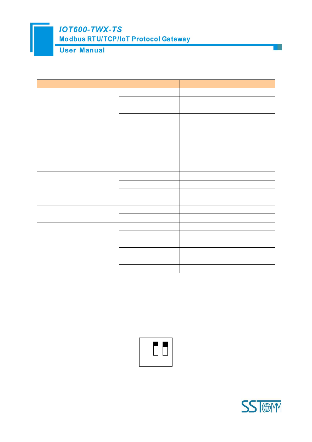
Pin
Function
1
GND
2
NC, not connected
3
24V+ , DC 24V
configuration to make the configuration take effect!
3.4 Interface
3.4.1 Power Interface
IOT600TWX-TS uses a 24V DC power supply which has two power interfaces and power redundant
function. When one power fails, another power can keep supplying power.
Power supply wiring is shown as below:
Page 9
WWW.SSTCOMM.COM
8
GND
NC
24V+
1
23GND
24V+
DC power: +24V
Power interface
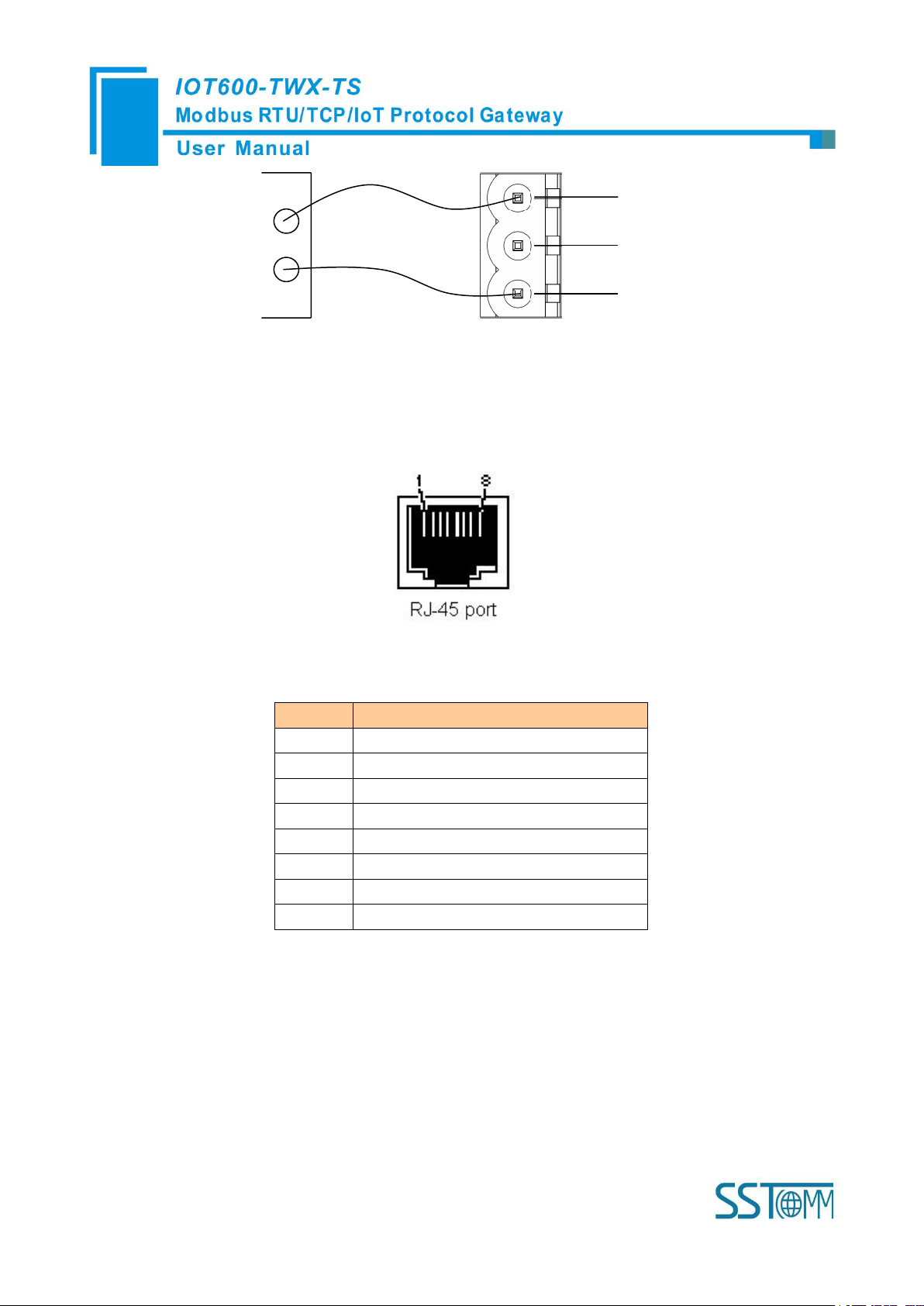
3.4.2 Ethernet Interface
Pin
Signal Description
S1
TXD+, Tranceive Data+, Output
S2
TXD-, Tranceive Data-, Output
S3
RXD+, Receive Data+, Input
S4
Bi-directional Data+
S5
Bi-directional Data-
S6
RXD-, Receive Data-, Input
S7
Bi-directional Data+
S8
Bi-directional Data-
Ethernet interface uses RJ-45 connector; its pin (standard Ethernet signal) is defined as below:
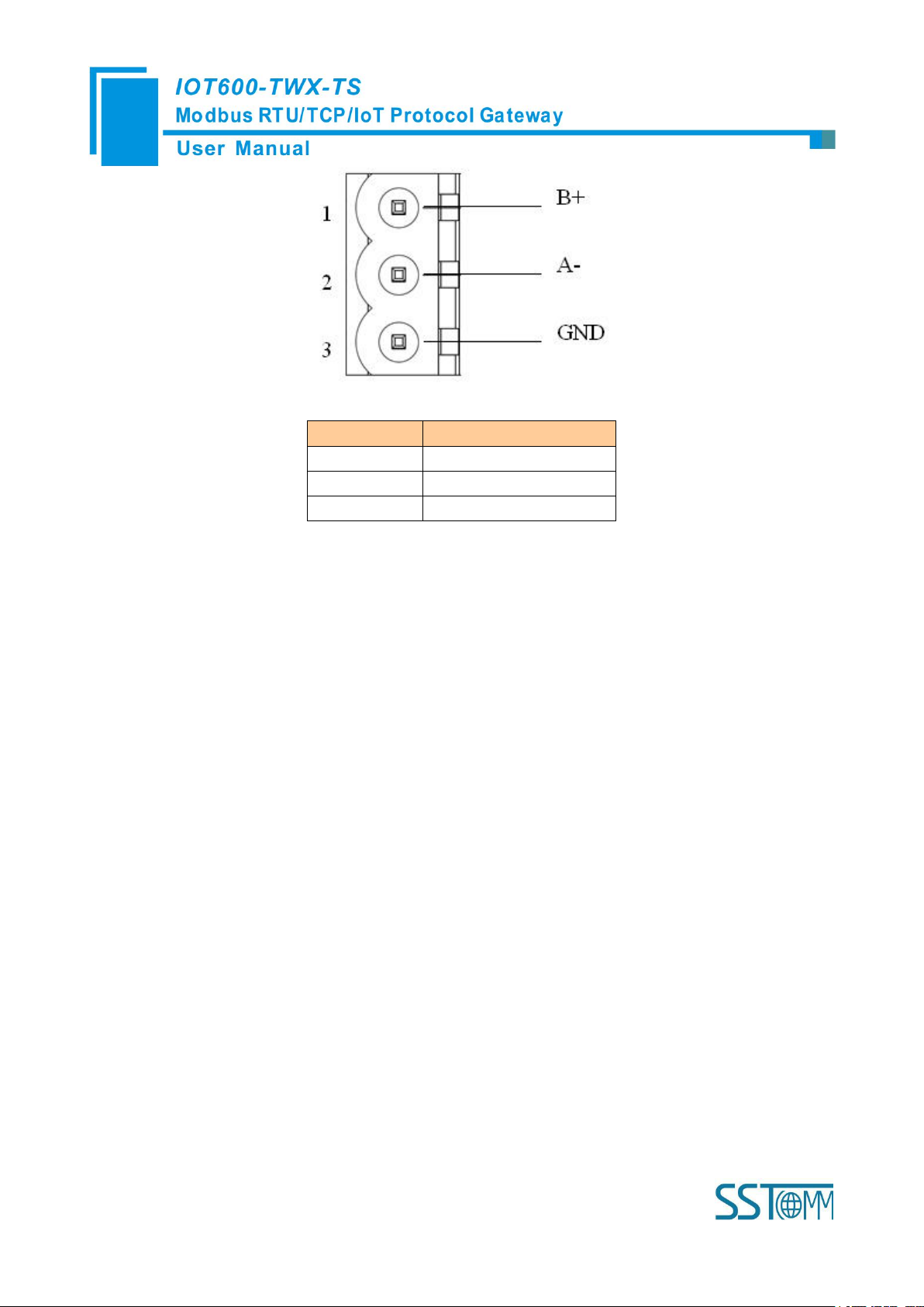
3.4.3 Serial Interface
Pin of RS485 interface is defined as below:
Page 10
WWW.SSTCOMM.COM
9
Pin
Description
1
B+, RS485
2
A-, RS485
3
GND
The RS485 interface of the IOT600-TWX-TS is a standard one, and the RS485 characteristics of the
product are shown as follows:
1. The basic characteristics of RS485 transmission technology
① Network topology: Linear bus, there are active bus terminal resistors at both sides.
② Transmission rate: 1200 bps~115.2Kbps.
③ Media: Shielded twisted-pair cable and also can cancel the shielding, depending on environmental
conditions (EMC).
④Site numbers: 32 stations per subsection (without repeater), and can up to 127 stations (with RS485
repeater).
⑤Plug connection: 3-pin pluggable terminal.
2. The main points on RS485 transmission equipment installation
①All the equipment are connected with RS485 bus;
②Subsection can be connected up to 32 sites;
③The farthest end of each bus has a termination resistor—120Ω 1/2W to ensure reliable operation of the
network.
Page 11

WWW.SSTCOMM.COM
10
D+D-GND
1
2
3
485+
485-
RS485 device
RS485 interface
RS485 device
RS485 device
485+
485-
485+
485-
…
When RS485 is in point to multipoint communication, in order to prevent the reflection and interference of
the signal, each of a terminal resistance is required at the farthest ends of the line, with a parameter of 120Ω 1/2W.
IOT600-TWX-TS serial port side has no parallel terminal resistance.
Page 12

WWW.SSTCOMM.COM
11
4 Instructions of Configuration Software
Connect the power lines, network lines and RS485 lines correctly;
Double click the configuration software (SST-IOT-CFG) and finish the configuration of IOT600-TWX-TS
Notes: The factory setting of IOT600-TWX-TS is 192.168.0.44, If you need to change, set the mode of the
configuration switch (bit 1) to the configuration (On) and restart the IOT600-TWX-TS.at this time the IP address
of IOT600-TWX-TS is 192.168.0.10(fixed), subnet mask is 255.255.255.0, and gateway address is 192.168.0.1.
Change the relevant parameters to the gateway as required, adjust the position of the dial switch to the factory
setting, and restart the gateway.
4.1 Notes before Configuring
SST-IOT-CFG is a software based on Windows platform,Before running the software, make sure the user’s
computer and IOT600-TWX-TS need to be in the same local network.
Double-click the icon to enter configuration interface:
4.2 Rapid Configuration
Page 13

WWW.SSTCOMM.COM
12
Power on IOT600-TWX-TS;
According to the actual situation of Modbus slave equipment, modify the IOT600-TWX-TS
configuration according to this specification, and download the configuration to IOT600-TWX-TS;
Connect Modbus slave equipment;
4.3 Search Equipment
Before configuring parameters of IOT600-TWX-TS, users need to search the gateway using the software.
The software provides two ways to search the gateway.
4.3.1 Search All Equipment in Ethernet
Click "Search Equipment" button of the main interface, the software will search all the available
IOT600-TWX-TS equipment and list them in the main interface.
4.3.2 IP Search
Click "IP Search" button of the main interface will pop up a dialog box which demands you to input IP
address.
Page 14

WWW.SSTCOMM.COM
13
After entering the correct IP address, the software will search IOT600-TWX-TS with this IP address in
the network, and list the information of the equipment in the main interface.
Page 15

WWW.SSTCOMM.COM
14
Notes:If users select the "IP Search", users need to enter correct IP address or it will not search equipment.
4.4 Configuration
Select the equipment to be configured in the list, and the "Locate", "Configuration", "Remote Reset", "New",
"Open" and "Save" buttons will become available:
Click "Configuration" button,The following window is popped out:
Page 16

WWW.SSTCOMM.COM
15
4.4.1 Configuring Ethernet Parameters
Ethernet parameters include: "Name", "Assign IP Mode", "IP Address", "Subnet Mask", "Default Gateway",
"DNS1" and "DNS2".
IOT Protocol Type: Web Socket
Device name: When connecting multiple IOT600-TWX-TS device, that is used to identify different
devices
Notes: The name can not have space, up to 32 characters.
Assign IP Mode: Manual Assign and DHCP
IP address: IP Address of IOT600-TWX-TS
Subnet Mask: set subnet mask of the equipment;
Default Gateway: set gateway address of the equipment;
DNS1: Preferred domain name server (LAN can not be set)
DNS2: Standby domain name server
URL and port:URL and Port should separate with ":", and can not exceed 100 characters. Such as:
iot.bokaiyun.cn:443. Note: The port number is related to the "TLS Enable", and the port number can
only be 443 when "TLS Enable" is selected as Enable.
TLS Enable: Whether to use TLS encryption transmission. You can choose: Disable, Enalbe. Note:
The TLS enable is related to the port.
Retries: the connection to the cloud server failed and the number of reconnects. Default: 10
Page 17

WWW.SSTCOMM.COM
16
Connection timed out: Send a connection request to the cloud server, waiting for the server to respond
to the time. Default: 10
AppKey: Connecting to ThingWorx requires AppKey, and can not exceed 64 characters.
Push Data Cycle: After the connection is established with ThingWorx, This parameter is the cycle of
the data pushed to the ThingWorx cloud. Range 100 ~ 60000ms, default: 300ms.
4.4.2 Configuring Modbus Serial Port Parameters
Serial parameters include: "Baud Rate", " check bit", "Stop bits" and "Data Bits".
Baud rate: 1200,2400,4800,9600,19200,38400,57600,115200
Data Bits: 8 (currently only support 8 data bits)
check bit: Odd, Even, None, Space and Mark
Stop bits: 1, 2
Transmission mode: RTU
Response timeout: After the gateway sends request, it waits the Modbus slave's response for max time which
Page 18

WWW.SSTCOMM.COM
17
is in ms. The range of the parameter value is 300 to 60000ms.
Delay between polls: Delay between polls means delay between a response has been received and sending
next request. The range of the parameter value is 0 to 2500ms
Output mode: There are two types of output: Cycle: the write command will be sent periodically; Change of
Value: when the output data change, the write command will be sent;
Scan rate: Scan Rate is ratio of fast scan to slow scan
Enable Auto Demotion: When Enable Auto Demotion and a command is a fast scan command without
correct response for N times, then the command will demote a slow scan command.
Auto Demotion: Setting Modbus command does not respond to resending the times
Auto Demotion time: When the Demotion Time timeout the command will promote a fast command. How to
Action after N successive Response Timeout: Clear Data; Hold Data
Note: the shadow’s parameter can not be changed.
4.4.3 Configuring Modbus TCP Master Parameters
Protocol Type selection: Modbus TCP Master, Modbus TCP Slave
Response timeout: After the gateway sends request, it waits the Modbus slave’s response for max time
Which is in ms. the range of the parameter value is 300 to 60000ms.Default value is
1000ms
Delay between polls: Delay between polls means delay between a response has been received and
Page 19

WWW.SSTCOMM.COM
18
sending next request. The range of the parameter value is 0 to 2500ms.Default value is 3ms
Output mode: Cycle, Change of Value
Cycle: the write command will be sent periodically;
Change of Value: when the output data change, the write command will be sent;
4.4.4 Configuring Modbus Command
1.Add nodes and Delete nodes
Right click "Modbus Master I"and select "Add Node"
Right click on the node to be deletedand select "Delete Node"
2.Add commands
Right click "Node ()" and select "Add command"
Page 20

WWW.SSTCOMM.COM
19
Select the command: Double click the command
For each Modbus command setting, the SST-IOT-CFG software automatically maps the Modbus command to
the corresponding attributes after the completion.
Page 21

WWW.SSTCOMM.COM
20
"Property type": Number, Boolean;
Read Input Register: Mapping to Number object;
Read Holding Register: Mapping to Number object;
Read Coil Status: Mapping to Boolean object;
Read Input Status: Mapping to Boolean object;
Force Single Coil: Mapping to Boolean object;
Force Multiple Coils: Mapping to Boolean object;
Preset Single Register: Mapping to Number object;
Preset Multiple Registers: Mapping to Number object;
Property name": you can edit and modify, the maximum data length is 20
"
"Register Count ":The Register Count can be selected as "1","2"and"4",Default value is 1
"Data type": BOOL, UINT16, INT16, UINT32, Float, INT32, UINT32V, INT32V, FloatV, Double, DoubleV,
INT64, NT64V, UINT64, UINT64V
"scale": you can edit and modify, The range of the parameter value is 0.001~1000, Default value is 1.0
Page 22

WWW.SSTCOMM.COM
21
4.4.5 Configuring Modbus TCP Slave Parameters
The Starting Address of Coil:Range 0~65535. Default 0.
The size of Coil: is the length which Modbus TCP master can access from the Starting Address of Coil in
IOT600-TWX-TS.
The Starting Address of Input Bit:Range 0~65535. Default 0.
The Size of Input Bit: is the length which Modbus TCP master can access from the Starting Address of Input
Bit in IOT600-TWX-TS
The Starting Address of Holding Register:Range 0~65535. Default 0.
The Size of Holding Register: is the length which Modbus TCP master can access from the Starting Address
of Holding Register in IOT600-TWX-TS
The Starting Address of Input Register:Range 0~65535. Default 0.
The Size of Input Register: is the length which Modbus TCP master can access from the Starting Address of
Input Register in IOT600-TWX-TS
4.5 Locate
When users manage multiple IOT600-TWX-TA, you can use "Locate" function to determine equipment that
you want to configure.
Users click on the "Locate" button, and the equipment is in Ethernet, the ENS and SNS orange indicator of
Page 23

WWW.SSTCOMM.COM
22
the equipment will flash alternately then the users can find it.
4.6 Remote Reset
The function of "remote reset" is restarting the selected equipment. Select the equipment in the list first, click
"Remote reset" button, it will pop up a confirmation dialog, then click "OK" to complete the operation.
Page 24

WWW.SSTCOMM.COM
23
4.7 Open/Save/Export EXCEL
Open: open and display the saved to the configuration data in a computer;
Page 25

WWW.SSTCOMM.COM
24
Export EXCEL: Excel document helps users to examine the configuration related
Page 26

WWW.SSTCOMM.COM
25
Save: Save the configuration parameters to the computer (.Chg) for later view, and pay attention to
saving the file.Select the device in the list, click "save", select the path to complete the operation.
Page 27

WWW.SSTCOMM.COM
26
4.8 Auto Assign Property Name/Download
Auto Assign Property Name: Naming the properties of thing automatically
Download: download the configuration information to IOT600-TWX-TS
Page 28

WWW.SSTCOMM.COM
27
4.9 New
Page 29

WWW.SSTCOMM.COM
28
Page 30

WWW.SSTCOMM.COM
29
5 Typical Application
IOT600-TWX-TS can connect Modbus slave devices to Ethernet in order to realize the communication
between Ethernet and serial devices.IOT600-TWX-TS plays a bridging role in communication.
The following is some typical application of .IOT600-TWX-TS:Ethernet master connects multiple serial port
Slave.
IOT600-TWX-TS collects Modbus RTU/TCP slave equipment data to the cloud, and exchange data
Page 31

WWW.SSTCOMM.COM
30
6 Installation
6.1 Machine Dimension
Size: 1.57 in (width)*4.92 in (height)*4.33 in (depth)
Page 32

WWW.SSTCOMM.COM
31
6.2 Installation Method
35mm DIN rail mounting
 Loading...