

Page 1

Modbus TCP / EtherNet/IP Gateway
GT200-MT-EI
User Manual
REV 1.4
SST Automation
E-mail: SUPPORT@SSTCOMM.COM
WWW.SSTCOMM.COM
Page 2

User Manual
Modbus TCP/EtherNet IP Gateway
GT 200 -MT-EI
WWW.SSTCOMM.COM
2
Catalog
1 Product Overview...................................................................................................................................................... 4
1.1 Product Overview........................................................................................................................................... 4
1.2 Product Features............................................................................................................................................. 4
1.3 Technical Specifications................................................................................................................................. 4
2 Quick Start Guide...................................................................................................................................................... 6
2.1 Connect to the power......................................................................................................................................6
2.2 Ethernet Interface............................................................................................................................................7
2.3 DIP Switch......................................................................................................................................................7
2.4 Software Installation.......................................................................................................................................8
3 Hardware Description................................................................................................................................................9
3.1 Appearance......................................................................................................................................................9
3.2 Indicators.......................................................................................................................................................10
3.3 Configuration switch.................................................................................................................................... 10
3.4 Interface........................................................................................................................................................ 11
3.4.1 Power Interface..................................................................................................................................11
3.4.2 Ethernet Interface...............................................................................................................................11
4 Instructions of Configuration Software................................................................................................................... 12
4.1 Notes before Configuration.......................................................................................................................... 12
4.2 User Interface................................................................................................................................................12
4.3 Equipment View Operation.......................................................................................................................... 14
4.3.1 Equipment View Interface.................................................................................................................14
4.3.2 Equipment View Operation Mode.....................................................................................................14
4.3.3 Equipment View Operation Types.....................................................................................................15
4.4 The Operation of Configuration Interface....................................................................................................16
4.4.1 EtherNet/IP Configuration View Interface........................................................................................16
4.4.2 Modbus TCP Configuration View Interface......................................................................................17
4.4.3 Node Configuration View Interface.................................................................................................. 19
4.4.4 Command Configuration View Interface.......................................................................................... 20
4.4.5 Comment Interface............................................................................................................................ 22
4.5 Conflict Detect..............................................................................................................................................22
4.5.1 Command List Operation.................................................................................................................. 23
4.5.2 Memory Mapping Operation.............................................................................................................24
4.6 Hardware Communication............................................................................................................................25
4.6.1 Ethernet Configuration...................................................................................................................... 25
4.6.2 Upload Configuration........................................................................................................................26
4.6.3 Download Configuration................................................................................................................... 27
4.7 Load and Save Configuration.......................................................................................................................29
4.7.1 Save Configuration Project................................................................................................................29
4.7.2 Load Configuration Project............................................................................................................... 29
Page 3

User Manual
Modbus TCP/EtherNet IP Gateway
GT 200 -MT-EI
WWW.SSTCOMM.COM
3
4.8 Excel File Output..........................................................................................................................................29
4.9 Monitor I/O Data.......................................................................................................................................... 30
5 Working Principle of Modbus TCP Master............................................................................................................. 33
6 Working Principle of Modbus TCP Slave............................................................................................................... 34
6.1 Working Principle......................................................................................................................................... 34
6.2 Network Status Monitor............................................................................................................................... 34
7 EtherNet/IP Connection Parameters Set..................................................................................................................36
8 How to Read/Write I/O Data using MSG................................................................................................................37
8.1 Read I/O Data............................................................................................................................................... 37
8.2 Write I/O Data...............................................................................................................................................41
9 Typical Application..................................................................................................................................................48
9.1 EtherNet/IP master PLCs interconnect with Modbus TCP master PLCs.................................................... 48
9.2 Modbus TCP slave devices connect to EtherNet/IP network.......................................................................49
10 Installation..............................................................................................................................................................50
10.1 Machine Dimension....................................................................................................................................50
10.2 Installation Method.....................................................................................................................................51
Page 4

User Manual
Modbus TCP/EtherNet IP Gateway
GT 200 -MT-EI
WWW.SSTCOMM.COM
4
1 Product Overview
Modbus TCP master or slave optional;
EtherNet/IP slave;
Redundant power;
Support network status monitor function;
Support I/O data monitor function;
Provide easy-to-use configuration software SST-EE-CFG.
a) Direct establish I/O connection to read/write I/O data;
b) Use MSG command to read/write I/O data;
1.1 Product Overview
GT200-MT-EI is a gateway which can realize the interconnection of different industrial Ethernet devices.
The gateway supports Modbus TCP master/slave and EtheNet/IP slave. It can finish the data exchange between
Modbus TCP network and EtherNet/IP network. Also, it supports the interconnection between Schneider PLC and
AB PLC and connecting the Modbus TCP slave devices to the EtherNet/IP network.
1.2 Product Features
1.3 Technical Specifications
[1] One Ethernet interface, Modbus TCP and EtherNet/IP shares this interface together;
[2] Ethernet 10/100M self-adaptive;
[3] IP address conflict detection;
[4] Support static IP and DHCP function;
[5] Act as a slave at the EtherNet/IP side, support ODVA standard EtherNet/IP communication protocol;
[6] Read&write of I/O data of EtherNet/IP supports two ways:
Page 5

User Manual
Modbus TCP/EtherNet IP Gateway
GT 200 -MT-EI
WWW.SSTCOMM.COM
5
[7] As Modbus TCP master, support visiting at most 36 different IP or Modbus TCP slave of different unit ID,
support function code 01H, 02H,03H, 04H, 05H, 06H, 0FH, 10H;
[8] Act as slave at the Modbus TCP side, support 36 TCP connections, support function code 03H, 04H, 06H,
10H;
[9] Max input bytes: 492 bytes, max output bytes: 492 bytes;
[10] Provide byte swap function: No swap, double-byte swap, four-byte swap;
[11] Working temperature: -4℉~140℉(-20℃~60℃), relative humidity: 5% ~ 95% (non-condensing);
[12] External Dimensions (W*H*D): 1.57 in*4.92 in*4.33 in (40mm*125mm*110mm);
[13] Installation: 35mm rail;
[14] Protection class: IP20;
Page 6
User Manual
Modbus TCP/EtherNet IP Gateway
GT 200 -MT-EI
WWW.SSTCOMM.COM
6
2 Quick Start Guide
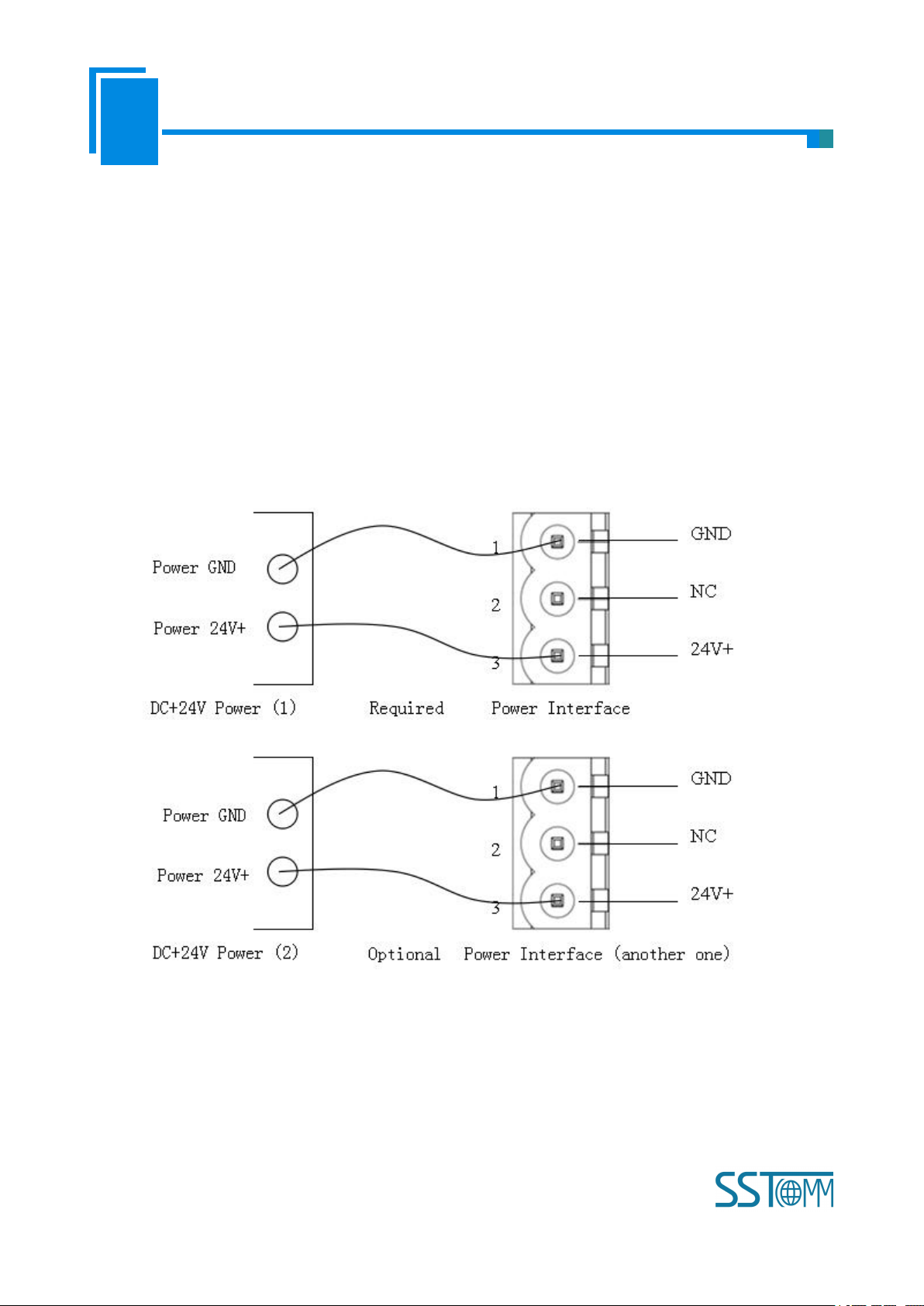
2.1 Connect to the power
Use DC 24V power supply, dual power interface, redundant function. User can use one power route or two
routes to provide supply.
When using two powers to supply power, another power can keep supplying power to ensure the normal
operation of equipment if one power fails.
Power wiring is as follows:
Page 7
User Manual
Modbus TCP/EtherNet IP Gateway
GT 200 -MT-EI
WWW.SSTCOMM.COM
7
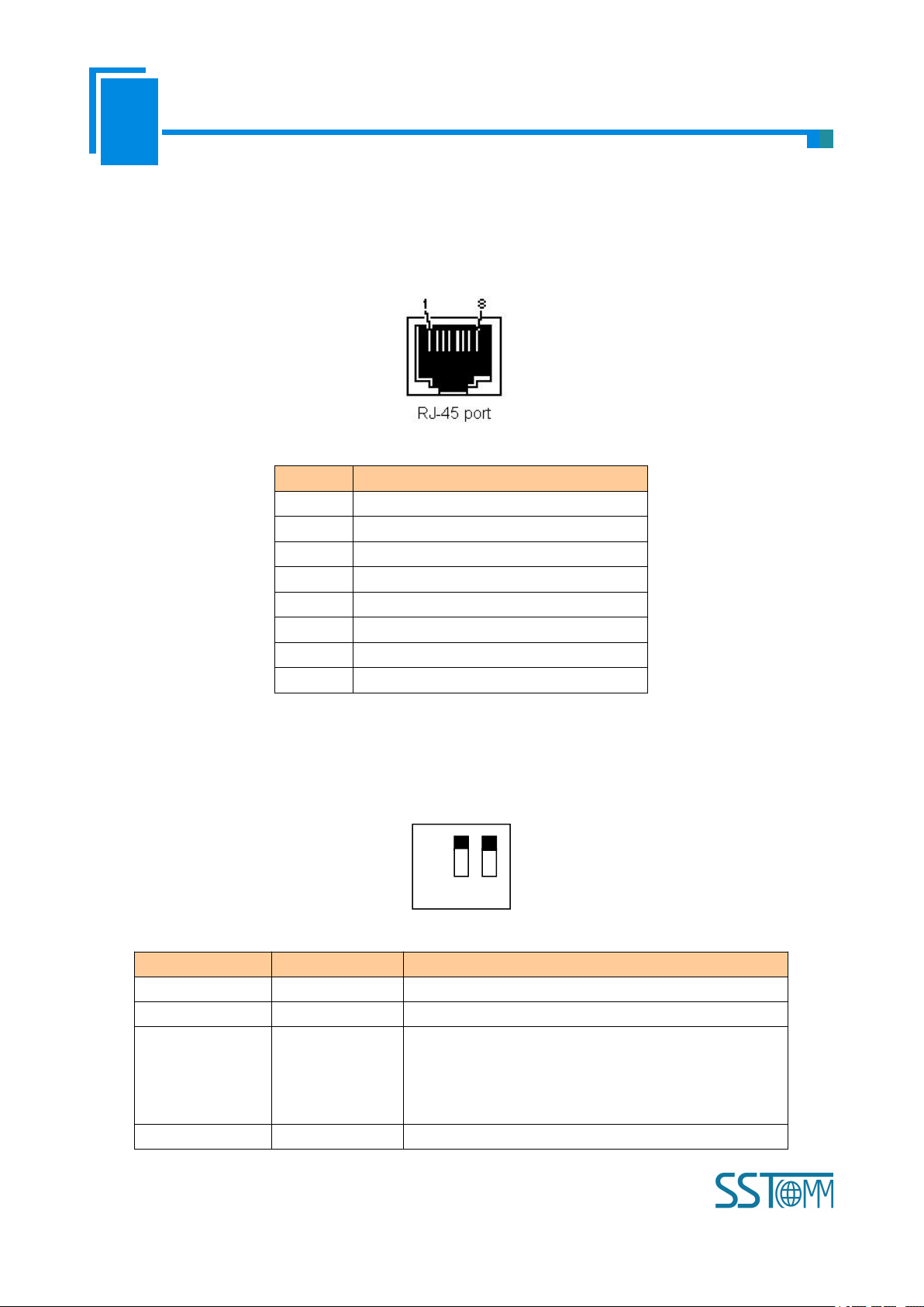
2.2 Ethernet Interface
Pin
Signal Description
S1
TXD+, Tranceive Data+, Output
S2
TXD-, Tranceive Data-, Output
S3
RXD+, Receive Data+, Input
S4
Bi-directional Data+
S5
Bi-directional Data-
S6
RXD-, Receive Data-, Input
S7
Bi-directional Data+
S8
Bi-directional Data-
Off
On 1 2
Mode (bit 1)
Function (bit 2)
Description
Off
Off
Run mode, allow reading and writing configuration data
Off
On
Run mode, forbid reading and writing configuration data
On
Off
Configuration mode, IP address is 192.168.0.10 (fixed),
this mode can read and write configuration data but cannot
finish communication between EtherNet/IP and Modbus
TCP
On
On
Reserved
Ethernet interface uses RJ-45 connector, 10/100M self-adaptive.
2.3 DIP Switch
The DIP switch is located at the bottom of the gateway, bit 1 is mode bit and bit 2 is function bit.
Page 8

User Manual
Modbus TCP/EtherNet IP Gateway
GT 200 -MT-EI
WWW.SSTCOMM.COM
8
2.4 Software Installation
Double click the SST-EE-CFG software; users can install it easily according to the instruction. Open the
configuration software and start the configuration of GT200-MT-EI. Detailed information please refer to the using
method of SST-EE-CFG software.
Note: The network factory setting of GT200-MT-EI is DHCP. If no DHCP Server on the network, users can
pull the bit 1 to ON and restart GT200-MT-EI to make the settings take effect. Now, the IP address of
GT200-MT-EI is 192.168.0.10 (fixed), subnet mask is 255.255.255.0, gateway address is 192.168.0.1.
Page 9

User Manual
Modbus TCP/EtherNet IP Gateway
GT 200 -MT-EI
WWW.SSTCOMM.COM
9
3 Hardware Description
Ethernet indicators
Dual power interface
Indicators(reserved)
Ethernet RJ45 interface
Configuration switch
3.1 Appearance
Page 10
User Manual
Modbus TCP/EtherNet IP Gateway
GT 200 -MT-EI
WWW.SSTCOMM.COM
10
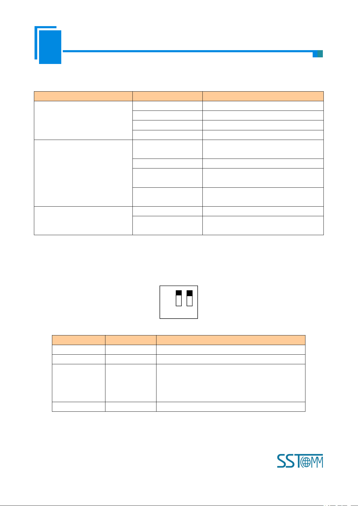
3.2 Indicators
Indicators
Status
Descriptions
ENS
(EtherNet/IP network status
indicators )
Green on
EtherNet/IP connection is established
Blinking(Green)
EtherNet/IP connection is not established
Red on
Indicates conflict with IP address
Blinking(Red)
EtherNet/IP connection is off or DHCP state
SNS
(Modbus TCP network status
indicators)
Green on
At least one Modbus TCP connection has
been established;
Blinking(Green)
Modbus TCP no connection
Blinking(Red)
Modbus TCP connection is off and no longer
exists
Blinking(Red)
(lasts 3 seconds)
Modbus TCP
connection is off
ENS (Orange) and SNS (Orange)
(Orange: Red and green light on at
the same time)
Simultaneously on
Start-up state
Blink alternately
Configuration state
Off
On 1 2
Mode (bit 1)
Function (bit 2)
Description
Off
Off
Run mode, allow reading and writing configuration data
Off
On
Run mode, forbid reading and writing configuration data
On
Off
Configuration mode, IP address is 192.168.0.10 (fixed),
this mode can read and write configuration data but cannot
finish communication between EtherNet/IP and Modbus
TCP
On
On
Reserved
3.3 Configuration switch
The DIP switch is located at the bottom of the gateway, bit 1 is mode bit and bit 2 is function bit.
Notes:
Restart GT200-MT-EI (power off and power on) after resetting the configuration to make the
configuration take effect!
Page 11
User Manual
Modbus TCP/EtherNet IP Gateway
GT 200 -MT-EI
WWW.SSTCOMM.COM
11
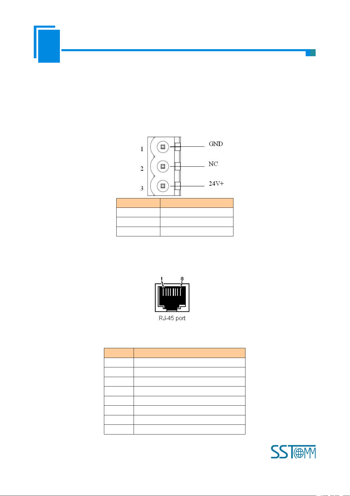
3.4 Interface
Pin
Function
1
GND
2
NC, not connected
3
24V+ , DC 24V
Pin
Signal Description
S1
TXD+, Tranceive Data+, Output
S2
TXD-, Tranceive Data-, Output
S3
RXD+, Receive Data+, Input
S4
Bi-directional Data+
S5
Bi-directional Data-
S6
RXD-, Receive Data-, Input
S7
Bi-directional Data+
S8
Bi-directional Data-
3.4.1 Power Interface
GT200-MT-EI has two power interfaces and power redundant function. When one power fails, another power
can keep supplying power.
3.4.2 Ethernet Interface
Ethernet interface uses RJ-45 connector; its pin (standard Ethernet signal) is defined as below:
Page 12
User Manual
Modbus TCP/EtherNet IP Gateway
GT 200 -MT-EI
WWW.SSTCOMM.COM
12
4 Instructions of Configuration Software
4.1 Notes before Configuration
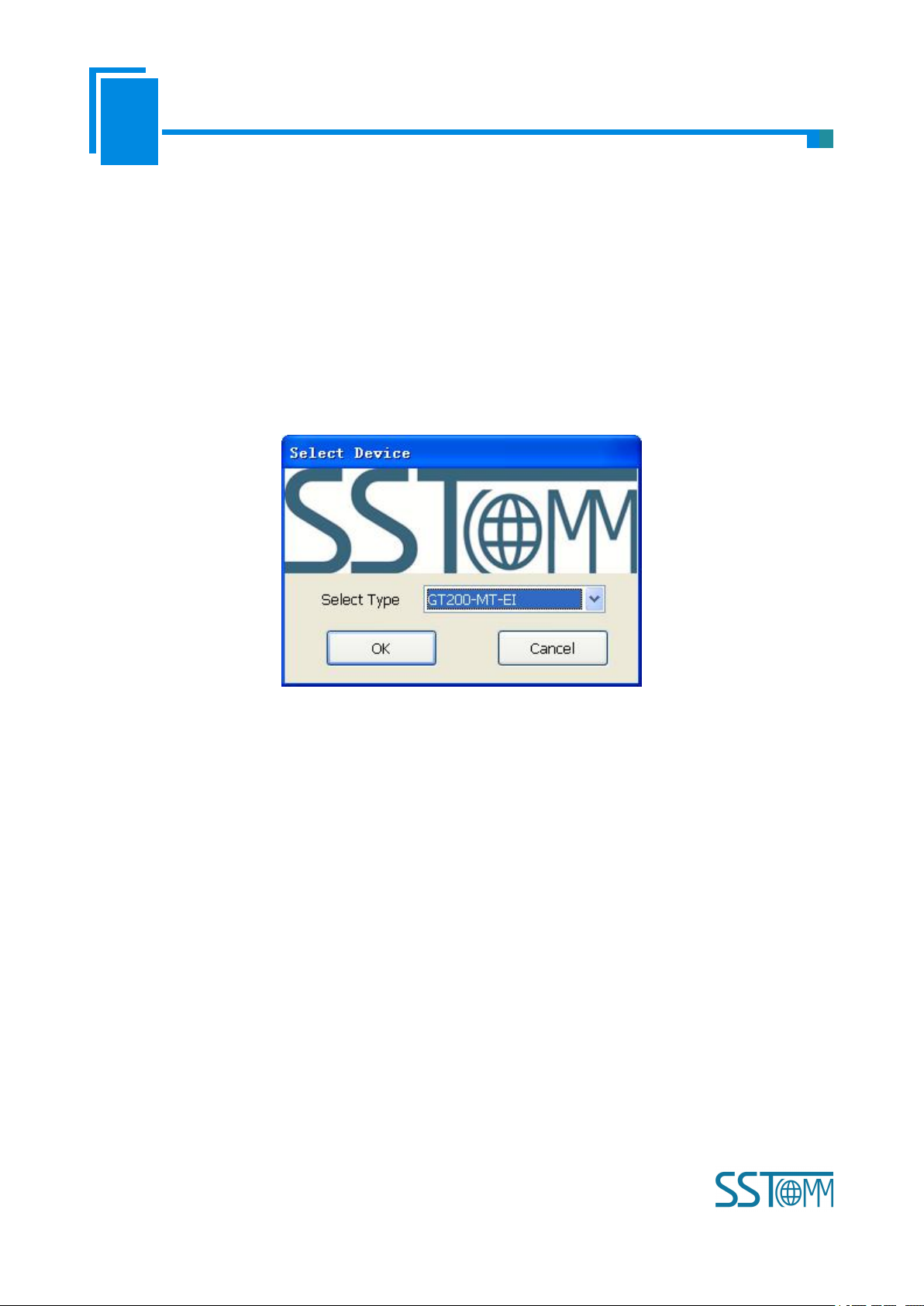
SST-EE-CFG is the software based on Windows platform. It is used to configure GT200-MT-EI series
gateway and set the relevant parameters of two different industrial Ethernet.
Double click the software icon on the desktop after installation to enter the “Select device” interface:
Select “GT200-MT-EI”, click OK to enter into the main interface of GT200-MT-EI (enter into the default
parameters setting interface of EtherNet/IP. Click the Ethernet type of equipment view interface to switch the
parameters setting interface.
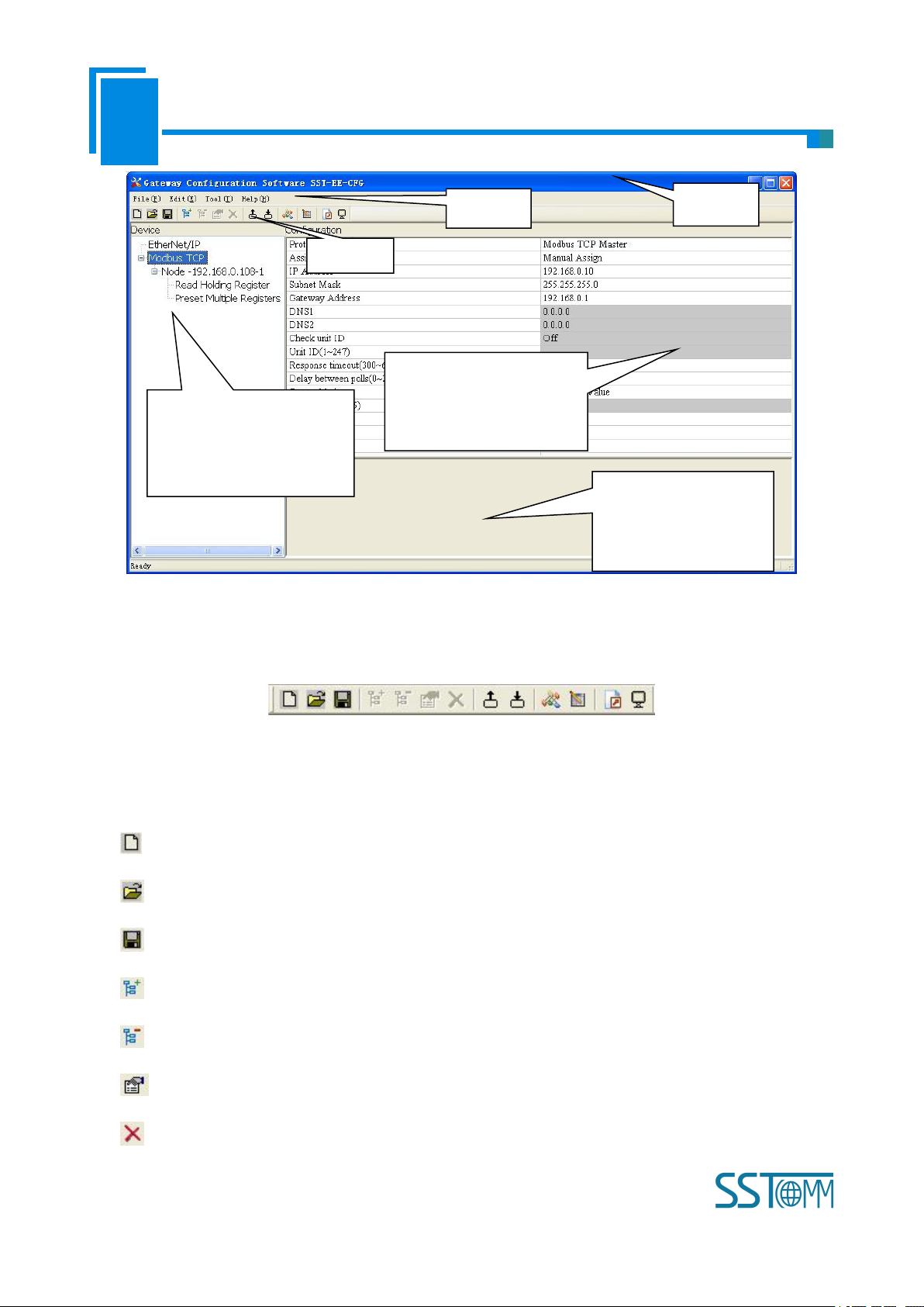
4.2 User Interface
The main interface of SST-EE-CFG includes: Title bar, Menu bar, Tool bar, Status bar, equipment plate,
configuration plate and comment plate.
Note: In this software, all gray parts are the part which cannot be changed.
Page 13
User Manual
Modbus TCP/EtherNet IP Gateway
GT 200 -MT-EI
WWW.SSTCOMM.COM
13
Tool Bar:
Tool Bar
Equipment plate:
Users can choose operation
object, includes Ethernet type
and adding node and command
Menu Bar
Title Bar
Configuration plate:
Input configuration parameters,
gray parts cannot be changed
Comment plate: Explain the
function of the
configuration options
Toolbar interface shown as follow:
The function from left to right is: New, Open, Save, Add Node, Delete Node, Add Command, Delete
Command, Upload Config, Download Config, Conflict Detect, Auto Mapping, Export Xls and Debug.
New: Create a new configuration project
Open: Open a configuration project
Save: Save current configuration
Add Node: Add a Modbus TCP slave node
Delete Node: Delete a Modbus TCP slave node
Add Command: Add a Modbus command
Delete Command: Delete a Modbus command
Page 14

User Manual
Modbus TCP/EtherNet IP Gateway
GT 200 -MT-EI
WWW.SSTCOMM.COM
14
Upload Config: Read the configuration information from the module and shown in the software
Download Config: Download the configuration file to the gateway
Conflict Detect: To check whether there are some conflicts with configured commands in the gateway
memory data buffer
Auto Mapping: Used to automatically calculate the mapped memory address without confliction by each
command
Export Xls: Export current configuration to the local hard disk, saved as .xls file
Debug: Monitor the gateway memory buffer data
4.3 Equipment View Operation
4.3.1 Equipment View Interface
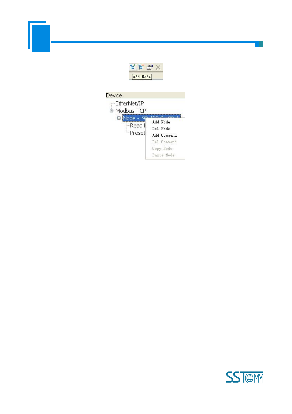
4.3.2 Equipment View Operation Mode
For equipment interface, support three operation modes: edit menu, edit toolbar and right click edit menu.
Page 15
User Manual
Modbus TCP/EtherNet IP Gateway
GT 200 -MT-EI
WWW.SSTCOMM.COM
15
4.3.3 Equipment View Operation Types
1)Add node: Left click on Modbus TCP or existing nodes, and then perform the operation of adding a new
node. Then there is a new node named "New node" under Modbus TCP.
2)Delete node: Left click on the node to be deleted, and then perform the operation of deleting the node. The
node and all commands will be deleted.
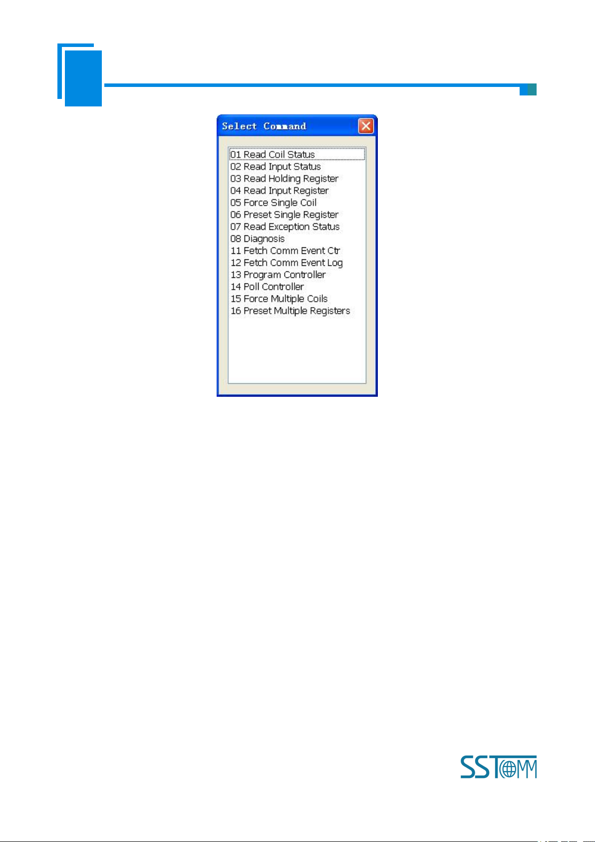
3 )Add commands: Left click on the node, and then perform the operation of adding command to add a
command for the node. It will pop up the command selecting dialog box for users to choose. Shown as below:
Select the command: Double click command item
Page 16
User Manual
Modbus TCP/EtherNet IP Gateway
GT 200 -MT-EI
WWW.SSTCOMM.COM
16
4 ) Delete commands: Left click on the command to be deleted, perform the operation of deleting the
command.
5 ) Edit node: Left click the node needs to be reset, and then set parameters of this node in configuration
interface.
6 ) Copy node: Left click the existing node, choose the node and execute the operation of copying nodes
(include all commands under the node)
7)Paste node: Left click and choose any existing node, execute operation of paste node. Then at the Ethernet
rear part you can see a new node (include all commands under the node); Node parameters of new node is default
setting, it needs to be reset.
4.4 The Operation of Configuration Interface
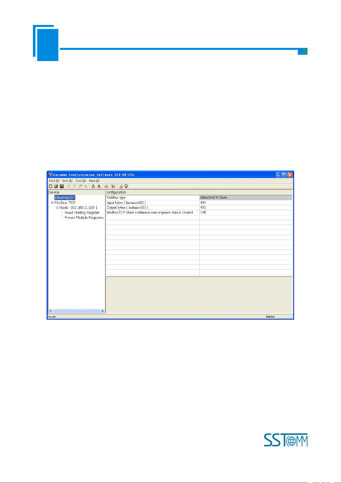
4.4.1 EtherNet/IP Configuration View Interface
In the equipment view interface, click Ethernet/IP; configuration view interface is as below:
Page 17
User Manual
Modbus TCP/EtherNet IP Gateway
GT 200 -MT-EI
WWW.SSTCOMM.COM
17
Configurable items include: Input bytes, Output bytes, Data clear of continuous no response of Modbus TCP
slave
Bus type: EtherNet/IP slave
Input bytes (Instance102): Input bytes number of EtheNet IP, range: 5~496, the default is 496
Output bytes number (Instance101): Output bytes number of EtherNet/IP, range: 1~492, the default is 492
Data clear of continuous no response of Modbus TCP slave: Valid in “Modbus TCP master” function, open,
close optional. Valid in “Modbus TCP master” function. Choose “open”, means to clear the input data of this slave
when continuous three times no response of one Modbus TCP slave.
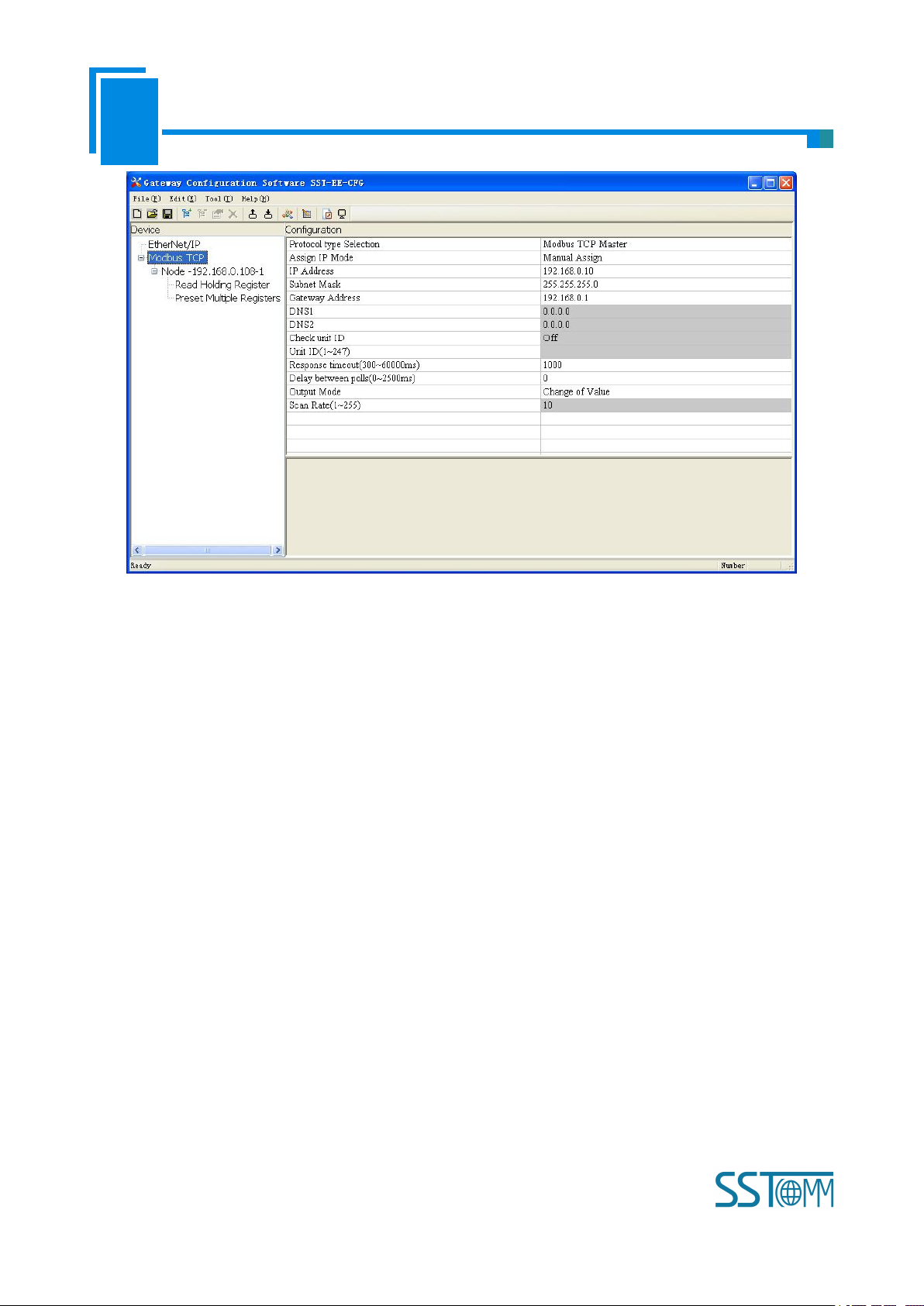
4.4.2 Modbus TCP Configuration View Interface
In equipment view interface, click “Modbus TCP”, when choosing different protocol, the configuration view
interface and configurable items will be different.
Protocol type select: Modbus TCP master
The configurable items include: Assign IP Mode, IP Address, Subnet Mask, Gateway Address, Response
Timeout, Delay between polls and Polling mode of output commands. As is shown below:
Page 18
User Manual
Modbus TCP/EtherNet IP Gateway
GT 200 -MT-EI
WWW.SSTCOMM.COM
18
Assign IP mode: Manual Assign, BOOTP and DHCP optional.
Response timeout: When Modbus TCP master sends out commands, it waits for the response from slave.
Range: 300~60000ms, the default is 1000.
Delay between polls: Receive the right response after one Modbus command has been sent or sending next
Modbus command after response timeout, the range is 0~ 2500ms, the default is 0.
Polling mode of output commands: continuous output, disable output and change-of-state output is optional.
Protocol type select: Modbus TCP slave
The configurable items include: Assign IP Mode, IP Address, Subnet Mask, Gateway Address, Check unit ID,
Unit ID, Network status indicator, High/Low byte swap. Shown as below:
Page 19

User Manual
Modbus TCP/EtherNet IP Gateway
GT 200 -MT-EI
WWW.SSTCOMM.COM
19
Assign IP Mode: Manual Assign, BOOTP and DHCP optional.
Check unit ID: open, close optional.
Unit ID (1~247): valid when “Check unit ID” is opened, 1~247 optional.
Network status indicator: both ends monitor with each other, EtherNet/IP monitor the network state of
Modbus TCP, Modbus TCP monitor EtherNet/IP network state and no indicating optional.
High/Low byte swap: No swap, double-byte swap, four-byte swap optional, the default is no swap.
4.4.3 Node Configuration View Interface
In equipment interface, click Modbus TCP, when selecting Modbus TCP at protocol type, right click
“Modbus TCP” and add new node. The node configuration view interface is shown as below:
Page 20

User Manual
Modbus TCP/EtherNet IP Gateway
GT 200 -MT-EI
WWW.SSTCOMM.COM
20
Configurable parameters: Unit ID, IP address to access Modbus TCP slaves, device status, memory-mapped
address and memory-mapped bit offset.
Unit ID: Slave address of Modbus TCP, 1~247 optional.
IP address of Modbus TCP slave needs visiting: Input IP address of Modbus TCP slave which gateway wants
to visit.
Device status: Open, close optional. When opened, “memory mapping address” and “memory mapping bit
offset” is optional. Users can see the communication state between this node and gateway in EtherNet/IP input
data.
Memory mapping address: Address range that equipment state is mapped in the module memory,
0x0000~0x01EB. Calculate by clicking “Auto mapping”.
Memory mapping bit offset: Bit x where equipment state is in memory mapping byte, 0~7.
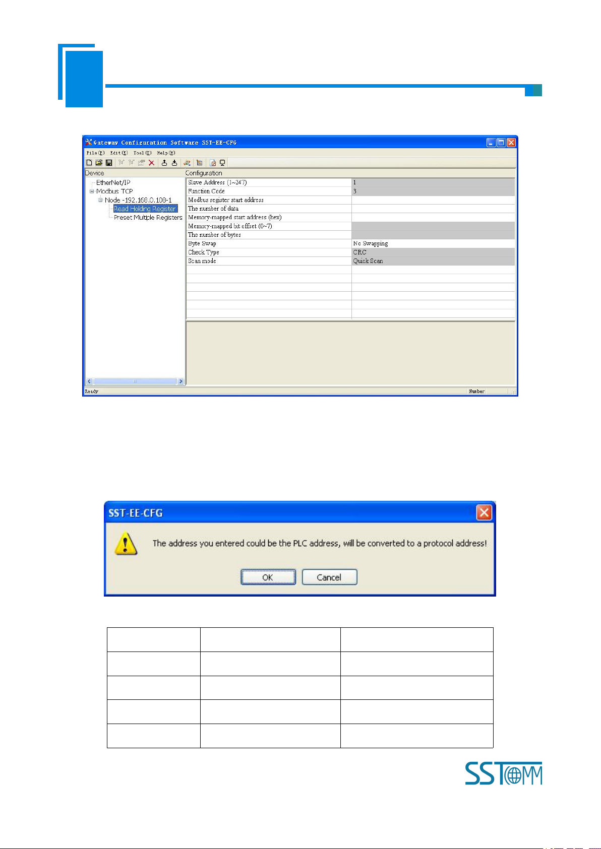
4.4.4 Command Configuration View Interface
In equipment view interface, click node command under Ethernet, the configuration view interface is shown
below:
Configurable parameters: Modbus register starting address, data number, Memory mapping starting address,
Page 21
User Manual
Modbus TCP/EtherNet IP Gateway
GT 200 -MT-EI
WWW.SSTCOMM.COM
21
Memory mapping bit offset and byte-swap.
Command
PLC address examples
Corresponding protocol address
Coil Status
00001~00010
00000~00009
Input Status
10001~10010
00000~00009
Holding Register
40001~40010
00000~00009
Input Register
30001~30010
00000~00009
Modbus register starting address: the starting address of the register/switching value/coil in Modbus salve
device. The range of the parameter value is 0 to 65535.
Note: This item of SST-EE-CFG indicates protocol address. When users input PLC address, it will pop up the
dialog box below. After clicking OK, the PLC address users input will be converted into the protocol address.
Here is the example of PLC address and corresponding protocol address.
Page 22

User Manual
Modbus TCP/EtherNet IP Gateway
GT 200 -MT-EI
WWW.SSTCOMM.COM
22
For example: When Modbus command is configured as 03H (read holding register), when users input 40001 in
this item (Modbus register starting address), it will pop up the dialog box after confirming. When clicking OK,
PLC address 40001 will be converted into 0.
Data number: Register/switching value/coil numbers.
Memory mapping starting address (HEX): Data starting address in module memory buffer.
Address range that data is mapped in the module memory
Read command: 0x0000~0x01EB
Write command: 0x4000~0x41EB
Users can also use this area after write command is about local data exchange: 0x0000~0x01EB
Memory mapping bit offset (0~7): For the bit operation command, means the position where the start bit is in
the byte, range0~7
Byte swap: No swap, double byte swap and four-byte optional.
4.4.5 Comment Interface
Comment interface displays the explanation of relevant configuration item. For example, when configuring
data numbers, comment interface is shown below:
4.5 Conflict Detect
It is used to check whether there exists confliction in “memory mapping data”. If users find confliction, it can
be adjusted in time. The interface is shown below:
Page 23

User Manual
Modbus TCP/EtherNet IP Gateway
GT 200 -MT-EI
WWW.SSTCOMM.COM
23
4.5.1 Command List Operation
It shows configured command in the command list interface. Check box before each command is used to
check the position of this command in memory mapping area. Click one command and check the box, it will show
the position where relevant commands occupy in the memory mapping area. Click the command again and
uncheck the box, the command will not be shown in the mapping area. This function will be used for confliction
detect among commands in memory mapping area.
Page 24

User Manual
Modbus TCP/EtherNet IP Gateway
GT 200 -MT-EI
WWW.SSTCOMM.COM
24
4.5.2 Memory Mapping Operation
Memory mapping area divides into input area and output area.
Input mapping address range: 0x0000~0x3FFF;
Output mapping address range: 0x4000~0x7FFF.
Each grid represents one byte address.
Green: read command is shown in input mapping area, it will be in green without conflict.
Yellow: Write command: When address mapping area is located in input area, it will be in yellow without
conflict;
Blue: When address mapping area is located in output area, it will be in blue without conflict.
Red: In input area or output area, different command occupied on the same byte, this byte area will be in red.
For bit operation command, the above grid displaying meaning works the same.
Click input/output area grids, each bit of relevant byte in the grid will show whether each bit is occupied. As
is shown below:
Page 25

User Manual
Modbus TCP/EtherNet IP Gateway
GT 200 -MT-EI
WWW.SSTCOMM.COM
25
4.6 Hardware Communication
The menu item of hardware communication is listed below:
4.6.1 Ethernet Configuration
Users can select whether to use the search function. When users use search function, it will search all
GT200-MT-EI equipment when uploading and downloading the configuration. When users don’t use the search
function, users must appoint the IP address of equipment which needs to be connected. It will only list one
equipment when uploading and downloading the configuration.
Page 26

User Manual
Modbus TCP/EtherNet IP Gateway
GT 200 -MT-EI
WWW.SSTCOMM.COM
26
Please click “OK” to confirm your choice, click “cancel” will lead to starting search function.
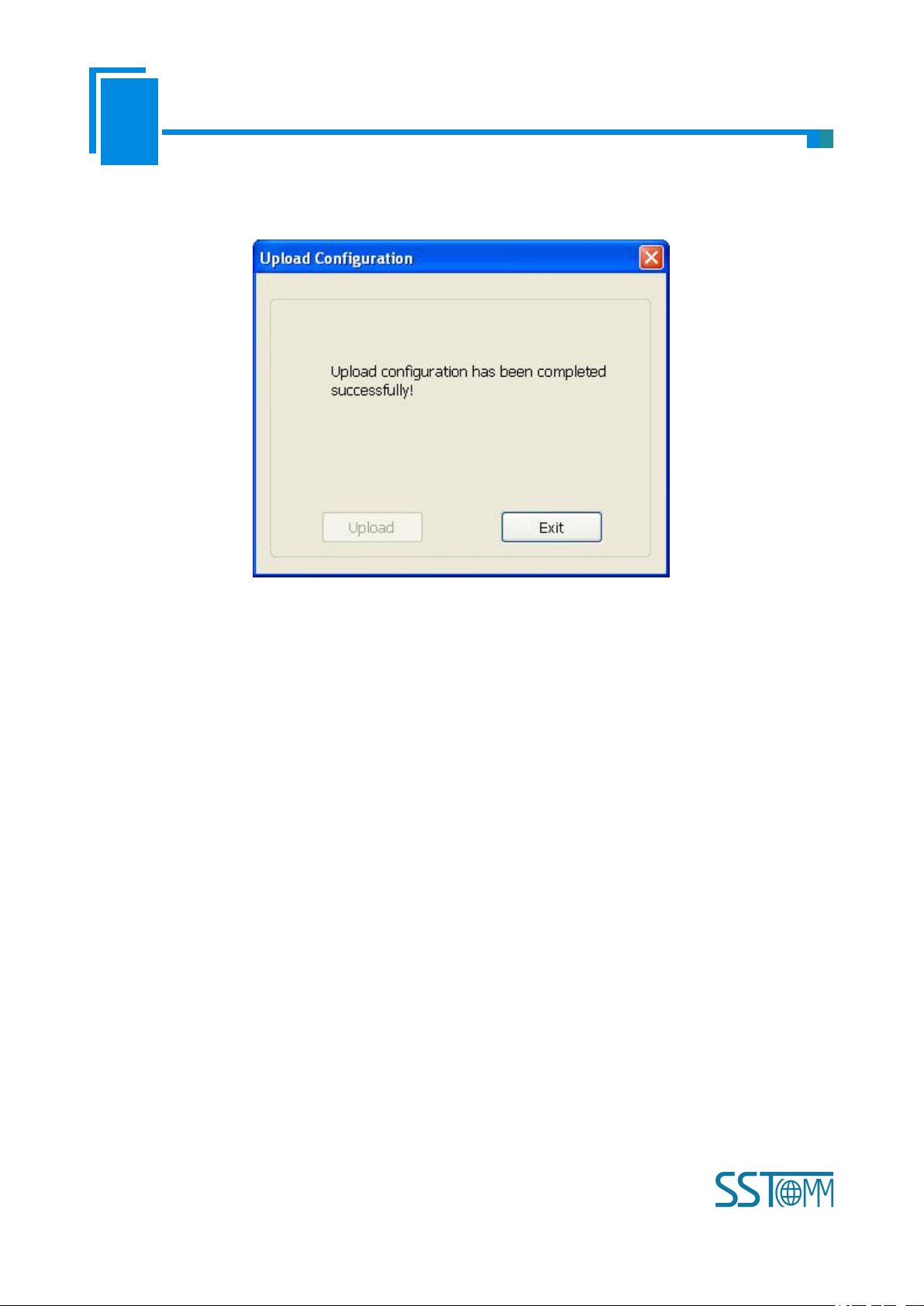
4.6.2 Upload Configuration
Choose upload configuration, it will pop up the dialog box of searching equipment:
Click “refresh” button will search equipment on the Ethernet again.
Page 27
User Manual
Modbus TCP/EtherNet IP Gateway
GT 200 -MT-EI
WWW.SSTCOMM.COM
27
Select the equipment you want to configure and click “Sign In” to enter into the upload dialog box. Upload
the configuration information from the equipment to the software, the interface is shown below:
4.6.3 Download Configuration
The operation of download configuration is the same as upload configuration:
Page 28

User Manual
Modbus TCP/EtherNet IP Gateway
GT 200 -MT-EI
WWW.SSTCOMM.COM
28
Notes: Before downloading, please confirm all configurations have been completed and right.
Page 29

User Manual
Modbus TCP/EtherNet IP Gateway
GT 200 -MT-EI
WWW.SSTCOMM.COM
29
4.7 Load and Save Configuration
4.7.1 Save Configuration Project
Select “Save” and save the configured project as .chg file.
4.7.2 Load Configuration Project
Select “Open” and open the saved .chg file.
4.8 Excel File Output
Excel configuration Excel file will help users to check the relevant configuration.
Select the export xls icon , export the configuration information to excel and save. Select the appropriate
path, shown as below:
Page 30

User Manual
Modbus TCP/EtherNet IP Gateway
GT 200 -MT-EI
WWW.SSTCOMM.COM
30
4.9 Monitor I/O Data
This function is used to monitor the buffer data, click “Debug” button on the toolbar and it will pop up the
dialog box of searching equipment:
Page 31

User Manual
Modbus TCP/EtherNet IP Gateway
GT 200 -MT-EI
WWW.SSTCOMM.COM
31
Click “Sign In”, it will pop up the I/O data monitor dialog box below:
Page 32

User Manual
Modbus TCP/EtherNet IP Gateway
GT 200 -MT-EI
WWW.SSTCOMM.COM
32
Click “Save Content” button can save relevant content to the PC hard disk. This button becomes “Stop
saving”. If you want to finish saving, you can press “Stop saving” button. It can pause displaying buffer data by
clicking “Pause displaying”.
Page 33

User Manual
Modbus TCP/EtherNet IP Gateway
GT 200 -MT-EI
WWW.SSTCOMM.COM
33
5 Working Principle of Modbus TCP Master
Ethernet supports Modbus TCP function, described as below:
Data exchange of Modbus TCP and EtherNet/IP of GT200-MT-EI is set up through “mapping”. There are
two data buffer areas, one is EtherNet/IP network input buffer and the other is EtherNet/IP network output buffer.
Network input and output buffer is all for EtherNet/IP master. When the gateway is Modbus TCP master, Modbus
read command will write the read data to the network input buffer for EtherNet/IP accessing. Modbus write
register command gets data from network output buffer and export to the Modbus TCP slave equipment through
write command.
As is shown above: network input buffer range is 0x0000~0x01EB (function code 01H, 02H, 03H, 04H as
data input; function 05H, 06H, 15H, 16H as local data exchange); Network output buffer range is
0x4000~0x41EB (function code 05H, 06H, 15H, 16H as data output).
Ethernet can support configuring at most 48 commands, each one can read one group of continuous Modbus
registers.
Page 34

User Manual
Modbus TCP/EtherNet IP Gateway
GT 200 -MT-EI
WWW.SSTCOMM.COM
34
6 Working Principle of Modbus TCP Slave
Network input buffer
Network output buffer
… …
0004H
0001H
0000H
0002H
0003H
0005H
0006H
0006H
0004H
0001H
0002H
0000H
0003H
0005H
… …
Modbus
Write command 06,10H
Modbus
read command: 04H
Modbus
read command: 04H
Modbus
read command: 03H
6.1 Working Principle
Data exchange of Modbus TCP and EtherNet/IP of GT200-MT-EI is set up through “mapping”. There are
two data buffer areas, one is EtherNet/IP network input buffer and the other is EtherNet/IP network output buffer.
Network input and output buffer is all for EtherNet/IP. When the gateway is Modbus TCP slave, Modbus write
register command will write the read data to the network input buffer for EtherNet/IP accessing. Modbus read
command gets data from network output buffer and export to the Modbus TCP master equipment through
response message.
The gateway acts as Modbus TCP slave, support function: 03H, 04H, 06H and 10H.
Network input buffer is Modbus TCP master output at the Modbus TCP side. It is mapped to the Modbus
read holding register. Users can use No.3 command to read back. It supports 03H, 06H and 10H function code.
Register starting address is 40001(0).
Network output buffer is Modbus TCP master input. It is mapped to Modbus input register. Users can use
No.4 function code to read data. It supports 04H function code. Register starting address is 30001 (0).
6.2 Network Status Monitor
When the gateway acts as Modbus TCP slave, it has the network status monitor function. Described as
Page 35

User Manual
Modbus TCP/EtherNet IP Gateway
GT 200 -MT-EI
WWW.SSTCOMM.COM
35
below:
a. EtherNet/IP monitor data are located in the first word of input data, it monitors the numbers that Modbus
b. Modbus TCP slave monitor data is fixed on the register of 35001 (5000). When EtherNet/IP network
c. No matter open or close the monitor function, it can still get the network status of EtherNet/IP by reading
d. If opened, it will map the register which address is 35001 (5000) to the register which address is 30001
e. If closed, EtherNet/IP output data will be mapped to the address starting from 30001 (1).
TCP has been connected to master. If closed, then it doesn’t input data;
Notes: “Open” monitor function means: in the SST-EE-CFG configuration software, Ethernet parameters
“network status indicators” is selected as “two ends network monitors with each other” or “EtherNet/IP end
monitors Modbus TCP network status”. If “close” monitor function, that means in the configuration software,
this parameter is “Modbus TCP end monitors EtherNet/IP network status” or “no indicating”.
fails, the register is set to 0 and 1 if network is normal;
the register which address is 35001 (5000);
(0), EtherNet/IP output data starts to be mapped the address starting from 30002 (1);
Notes: “Open” monitor function means: in the SST-EE-CFG configuration software, Ethernet parameters
“network status indicators” is selected as “two ends network monitors with each other” or “Modbus TCP end
monitors EtherNet/IP network status”. If “close” monitor function, that means in the configuration software,
this parameter is “EtherNet/IP end monitors Modbus TCP network status” or “no indicating”.
Page 36

User Manual
Modbus TCP/EtherNet IP Gateway
GT 200 -MT-EI
WWW.SSTCOMM.COM
36
7 EtherNet/IP Connection Parameters Set
a. Input bytes number Instance102, range 5~496 bytes, the default value is 496 bytes;
b. Output bytes number Instance 101, range 1~492 bytes, the default value is 492 bytes;
c. Config bytes Instance113, 10 bytes (fixed).
Connection parameters the gateway provides are as below:
Input Instance 102 data length can be set in the software SST-EE-CFG, range 5~496 bytes, among them the
first 4 bytes is real-time frame header (reserved);
Output Instance101 data length can be set in the software SST-EE-CFG, range 1~492 bytes.
Take configuration parameters of RSLogix5000 as an example:
Notes: The “Size” (the bytes number that has been configured) in the above picture, is consistent with the
input/output bytes number of Instance which has been configured in the configuration software SST-EE-CFG). In
the above picture, “Size” is 62 (62x32/8=248) in the input bytes Instance102. Now, the relevant bytes number
should also be 248 in the configuration software.
Page 37

User Manual
Modbus TCP/EtherNet IP Gateway
GT 200 -MT-EI
WWW.SSTCOMM.COM
37
8 How to Read/Write I/O Data using MSG
The following RSLogix 5000 example will describe how to read/write I/O data using MSG.
8.1 Read I/O Data
Create a new project; it is in the “Offline” mode. Add two new tags “ReadTag” and “ReadData” under the
“Controller Tags” and set the type of “ReadTag” as “MESSAGE” and “ReadData” as “SINT[500]”.
Right click “ReadTag”, select “Configure “ReadTag””:
Page 38

User Manual
Modbus TCP/EtherNet IP Gateway
GT 200 -MT-EI
WWW.SSTCOMM.COM
38
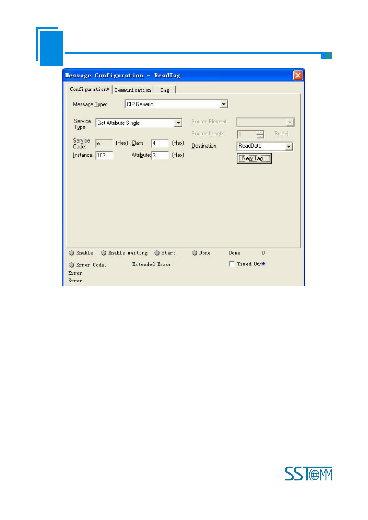
In the new pop-up window, it needs to set some parameters as below:
Message Type: CIP Generic
Service Type: Select “Get Attribute Single”, now, relevant service code will become “e (Hex)”
Class: 4 (Hex)
Instance: 102
Attribute: 3 (Hex)
Destination: Select “ReadData” label, now, the data that have been got will be saved in this tag.
Page 39
User Manual
Modbus TCP/EtherNet IP Gateway
GT 200 -MT-EI
WWW.SSTCOMM.COM
39
Select “Communication” label, first click “Browse” button; select the gateway PLC has connected with, click
“OK” to confirm:
Page 40

User Manual
Modbus TCP/EtherNet IP Gateway
GT 200 -MT-EI
WWW.SSTCOMM.COM
40
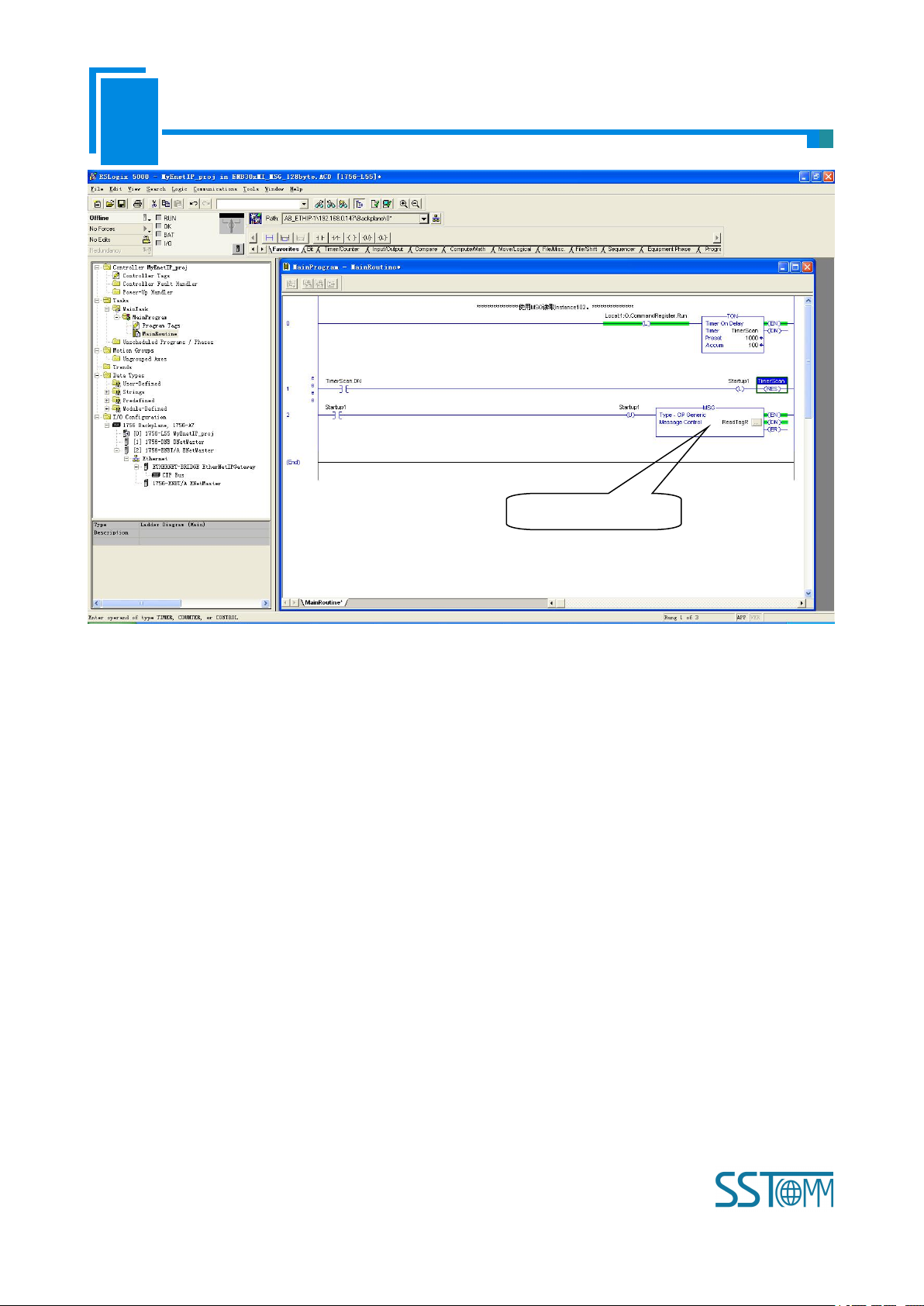
Shown as picture below, add a “MSG” command and select “ReadTag” as “Message Control” in the
“MainRoutine” of “MainProgram”. This is a simple command which can sent a read request, it still needs to add
some logic commands to trigger this command in common program. About the detailed information, please refer
to RSLogix5000.
Download the program to the PLC and set PLC into “Online” state.
Page 41
User Manual
Modbus TCP/EtherNet IP Gateway
GT 200 -MT-EI
WWW.SSTCOMM.COM
41
Click “Control Tags” and select “Monitor Tags”, unfold “ReadData”, you will see that PLC can read the data
PLC read-data command
of Modbus TCP master or Modbus TCP slave through the gateway GT200-MT-EI.
8.2 Write I/O Data
Enter the “Offline” mode, add two new tags “WriteTag” and WriteData” under the “Controller Tags”. Define
the type of “WriteTag” as “MESSAGE” and “WriteData” as “SINT[500]”:
Page 42

User Manual
Modbus TCP/EtherNet IP Gateway
GT 200 -MT-EI
WWW.SSTCOMM.COM
42
Enter the “Monitor Tags” interface; input some data in the “WriteData” tag. There data will be outputted to
GT200-MT-EI through PLC. Described as below picture, 0x10, 0x20, 0x30, 0x40, 0x50, 0x60, 0x70, 0x80 and
0x90 are the data that will be outputted.
Page 43

User Manual
Modbus TCP/EtherNet IP Gateway
GT 200 -MT-EI
WWW.SSTCOMM.COM
43
Right click “WriteTag”, select “Configure “WriteTag””:
Page 44

User Manual
Modbus TCP/EtherNet IP Gateway
GT 200 -MT-EI
WWW.SSTCOMM.COM
44
In the new pop-up window, it needs to configure as below:
Message Type: CIP Generic
Service Type: Select “Set Attribute Single”, now, relevant Service Code will become “10 (Hex)”
Class: 4 (Hex)
Instance: 101
Attribute: 3 (Hex)
Source Element: Select “WriteData” tag, it indicates the data in the “WriteData” tag will become the data
PLC outputs.
Page 45

User Manual
Modbus TCP/EtherNet IP Gateway
GT 200 -MT-EI
WWW.SSTCOMM.COM
45
Source Length: Use byte as unit, this value should be less than or equal to the current selecting bytes which
Instance represents (Configured bytes number in SST-EE-CFG).
Select “Communication” label, first click “Browse” button, select the gateway PLC connected in the new
window, click “OK” to confirm:
Page 46

User Manual
Modbus TCP/EtherNet IP Gateway
GT 200 -MT-EI
WWW.SSTCOMM.COM
46
Shown as below, add a “MSG” command in the “MainRoutine” of “MainProgram” and select “WriteTag” as
“Message Control”.
Download PLC program to the PLC and set PLC to “Online” state, the data in “WriteData” will be outputted
to Modbus TCP master or slave through GT200-MT-EI.
Page 47

User Manual
Modbus TCP/EtherNet IP Gateway
GT 200 -MT-EI
WWW.SSTCOMM.COM
47
PLC write-data command
PLC read-data command
Page 48
User Manual
Modbus TCP/EtherNet IP Gateway
GT 200 -MT-EI
WWW.SSTCOMM.COM
48
9 Typical Application
GT200-MT-EI can connect Modbus TCP slave equipment to the EtherNet/IP network, it can also realize the
interconnection between Schneider Modbus TCP master PLC and AB EtherNet master PLC.
Here are some typical applications of GT200-MT-EI.
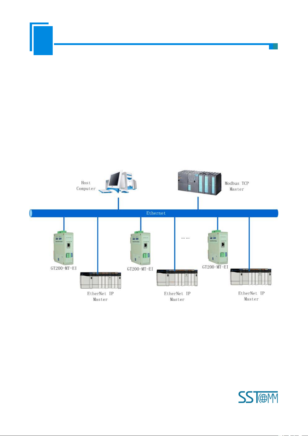
9.1 EtherNet/IP master PLCs interconnect with Modbus TCP master
PLCs
In this case, different EtherNet/IP masters are connected to the same Modbus TCP master PLC with many
GT200-MT-EI gateways through Ethernet switch machine, in this way many EtherNet/IP master PLC can
communicate with Modbus TCP master PLC.
Note: GT200-MT-EI needs to be configured EtherNet/IP slave and Modbus TCP slave.
Page 49

User Manual
Modbus TCP/EtherNet IP Gateway
GT 200 -MT-EI
WWW.SSTCOMM.COM
49
9.2 Modbus TCP slave devices connect to EtherNet/IP network
In this application case, GT200-MT-EI gateway needs to be configured as EtherNet/IP slave and Modbus
TCP master. EtherNet/IP master devices, Modbus TCP slave devices, and industrial Ethernet gateway
GT200-MT-EI connect with each other through Ethernet switch machine. It can realize the data uploading from
Modbus TCP slave to EtherNet/IP master through data mapping of GT200-MT-EI.
Page 50
User Manual
Modbus TCP/EtherNet IP Gateway
GT 200 -MT-EI
WWW.SSTCOMM.COM
50
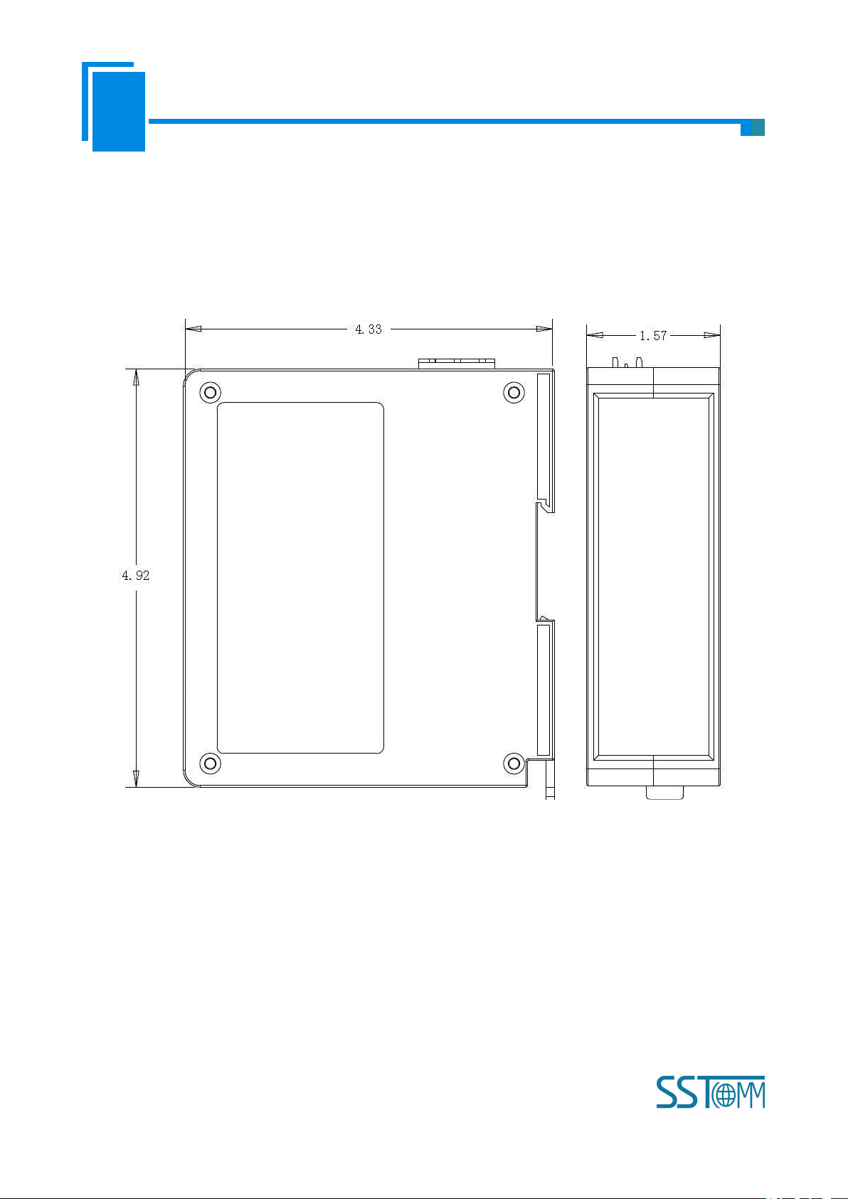
10 Installation
10.1 Machine Dimension
Size: 1.57 in (width)*4.92 in (height)*4.33 in (depth)
Page 51

User Manual
Modbus TCP/EtherNet IP Gateway
GT 200 -MT-EI
WWW.SSTCOMM.COM
51
10.2 Installation Method
35mm DIN rail mounting
 Loading...