

Page 1

HART/ Modbus Serial Gateway
GT200-HT-RS
User Manual
V 2.3 REV B
SST Automation
E-mail: SUPPORT@SSTCOMM.COM
WWW.SSTCOMM.COM
Page 2

WWW.SSTCOMM.COM 2
Catalog
1 Product Overview...................................................................................................................................................... 4
1.1 Product Function.............................................................................................................................................4
1.2 Product Features............................................................................................................................................. 4
1.3 Technical Specifications.................................................................................................................................4
1.4 Safety and Explosion-Proof Features............................................................................................................. 5
1.5 Related Products............................................................................................................................................. 5
1.6 Revision History............................................................................................................................................. 5
2 Quick Start Guide...................................................................................................................................................... 6
2.1 Configuration of Gateway Parameters........................................................................................................... 6
2.1.1 Pre-configured Settings....................................................................................................................... 6
2.1.2 Software Configuration....................................................................................................................... 6
2.2 Function Demo............................................................................................................................................... 9
3 Hardware Descriptions.............................................................................................................................................11
3.1 Product Appearance...................................................................................................................................... 11
3.2 Indicators.......................................................................................................................................................12
3.3 DIP Switch/Button........................................................................................................................................12
3.3.1 DIP Switch.........................................................................................................................................12
3.3.2 Modbus Address Setting Button........................................................................................................13
3.3.3 Internal/External Sampling Resistor Switch..................................................................................... 13
3.4 Interface........................................................................................................................................................ 14
3.4.1 Power Interface..................................................................................................................................14
3.4.2 RS-485/RS-422 Interface.................................................................................................................. 14
3.4.3 RS-232 Interface................................................................................................................................15
3.4.4 HART Interface..................................................................................................................................16
3.4.5 Mini B Type USB.............................................................................................................................. 16
3.5 Topology of GT200-HT-RS and Fieldbus Devices......................................................................................17
4 Software Instructions............................................................................................................................................... 19
4.1 Software Interface Description.....................................................................................................................19
4.2 Software Functional Specifications..............................................................................................................21
4.2.1 Connect with the Hardware............................................................................................................... 21
4.2.2 Upload configuration.........................................................................................................................22
4.2.3 Configure the Fieldbus...................................................................................................................... 22
4.2.4 Configure the HART Fieldbus...........................................................................................................25
4.2.5 Conflict Detection..............................................................................................................................32
4.2.6 AutoMap............................................................................................................................................ 33
4.2.7 Download Configuration................................................................................................................... 33
4.2.8 Memory Data Display....................................................................................................................... 33
4.2.9 Diagnose............................................................................................................................................ 34
Page 3

WWW.SSTCOMM.COM 3
4.2.10 Serial Debug.................................................................................................................................... 38
4.2.11 Switching Tools............................................................................................................................... 39
4.2.12 Use USB Port...................................................................................................................................40
5 Working Principle.................................................................................................................................................... 45
5.1 Flowchart of Executing One HART Command........................................................................................... 48
5.2 Universal Send and Receive Data................................................................................................................ 48
5.3 Trigger Command......................................................................................................................................... 49
5.4 Data Exchange with Modbus........................................................................................................................50
6 Installation................................................................................................................................................................51
6.1 Machine Dimension......................................................................................................................................51
6.2 Installation Method.......................................................................................................................................51
Page 4

WWW.SSTCOMM.COM 4
1 Product Overview
Powerful Serial function: Support the interconnection between HART and Modbus , also support transparent
Multi debugging functions: It can display the exchanging data, and diagnosis the HART command
[1] Used as a primary or a secondary HART master;
[2] Supports one HART-channel, under multi-point mode, support connecting at most 13 HART slaves with
[3] Supports single-point and multi-point mode at the HART side;
[4] Under single-point mode, support data burst operation;
[5] Supports all commands of the HART protocol;
[6] Each HART command can be configured for change-of-state output, polling output, initialization output or
[7] Supports up to 128 HART commands, HART output data buffer is up to 1000 bytes, and the input data buffer
[8] Supports an internal or external HART sampling resistor;
[9] Supports serial RS-232, RS-485 and RS-422, baud rate supports: 300, 600, 1200, 2400, 4800, 9600, 19.2K,
1.1 Product Function
GT200-HT-RS is a gateway that can provide a seamless connection between HART and Modbus. At HART
side it can be configured as a primary master or the secondary master, and acts as slave at the Modbus side.
1.2 Product Features
transmission between HART and serial port.
1.3 Technical Specifications
gateway internal resistor and support connecting 15 HART slaves with an external resistor (250Ω);
disable output;
is up to 1600 bytes;
Page 5
WWW.SSTCOMM.COM 5
38.4K, 57.6K, 115.2Kbps;
[10] The serial port can be configured as Modbus slave, supports modbus function code: 03H, 04H, 06H, 10H;
[11] Modbus slave supports RTU and ASCII communication;
[12] The serial port can be configured as universal mode, and achieve transparent data transmission with HART
[13] Power: 24VDC (9V~30V), 80mA (24VDC);
[14] Working circumstance temperature: -4℉~140℉(-20℃~60℃), Humidity: 5%~ 95%;
[15] External dimensions (W*H*D): 0.98 in*3.94 in *3.54 in (25mm*100mm*90mm);
[16] Installation: 1.38 in (35mm) DIN RAIL;
[17] Protection Level: IP20;
Revision
Date
Chapter
Description
REV A
21/9/2015
All
New software version
REV B
1/4/2016
All
Hardware Update
slave devices;
1.4 Safety and Explosion-Proof Features
GT200-HT-RS is not the product with the features of safety and explosion-proof, please put it in the control
room when using.
1.5 Related Products
The related products include: GT200-HT-DP, GT200-DP-RS etc.
If you want to get more information about these products, please visit SSTCOMM website:
http://www.sstcomm.com.
1.6 Revision History
Page 6

WWW.SSTCOMM.COM 6
2 Quick Start Guide
1. Turn gateway’s configuration bit of DIP switch(refer to chapter 3.3.1) to “ON”;
2. Connect the Gateway’s RS-232/USB interface and the serial port of the computer with a serial cable, wiring
3. Power on the gateway, the LED display shows “CF”, indicates that the gateway is in the configuration mode.
1. Run the SST-HT-CFG software installed on your computer.
2. Click “Fieldbus” in the tree view on the left, the configuration table is shown on the right as below:
The following example introduces the use method of the Gateway.
2.1 Configuration of Gateway Parameters
2.1.1 Pre-configured Settings
methods see chapter 3.4.3 of this manual;
Run the SST-HT-CFG to start the gateway configuration.
2.1.2 Software Configuration
Page 7

WWW.SSTCOMM.COM 7
3. Click “HartChannel0” in the tree view on the left, the configuration table is shown on the right as below:
Note: HART protocol specifies that the slave device which address is 0 must work in single-point mode. In
single-point mode the digital communication and analog communication is allowed to exist at the same time. The
Slave with address 1~15 works in multi-point mode. In multi-point mode the analog output of the device is the
minimum value (e.g. 4mA), only allows digital communication. The protocol also specifies that the default factory
address of field device is 0.
4. Right-click HartChannel0, in the pop-up menu, select “Add Node”, as shown below:
5. Right-click “Node(0)”, in the pop-up menu selects “Add Command” to add a command (Command ID1) in
the dialog box, and then click OK to return.
Page 8

WWW.SSTCOMM.COM 8
6. Click the “Command ID1”, the configuration table on the right is configured as below:
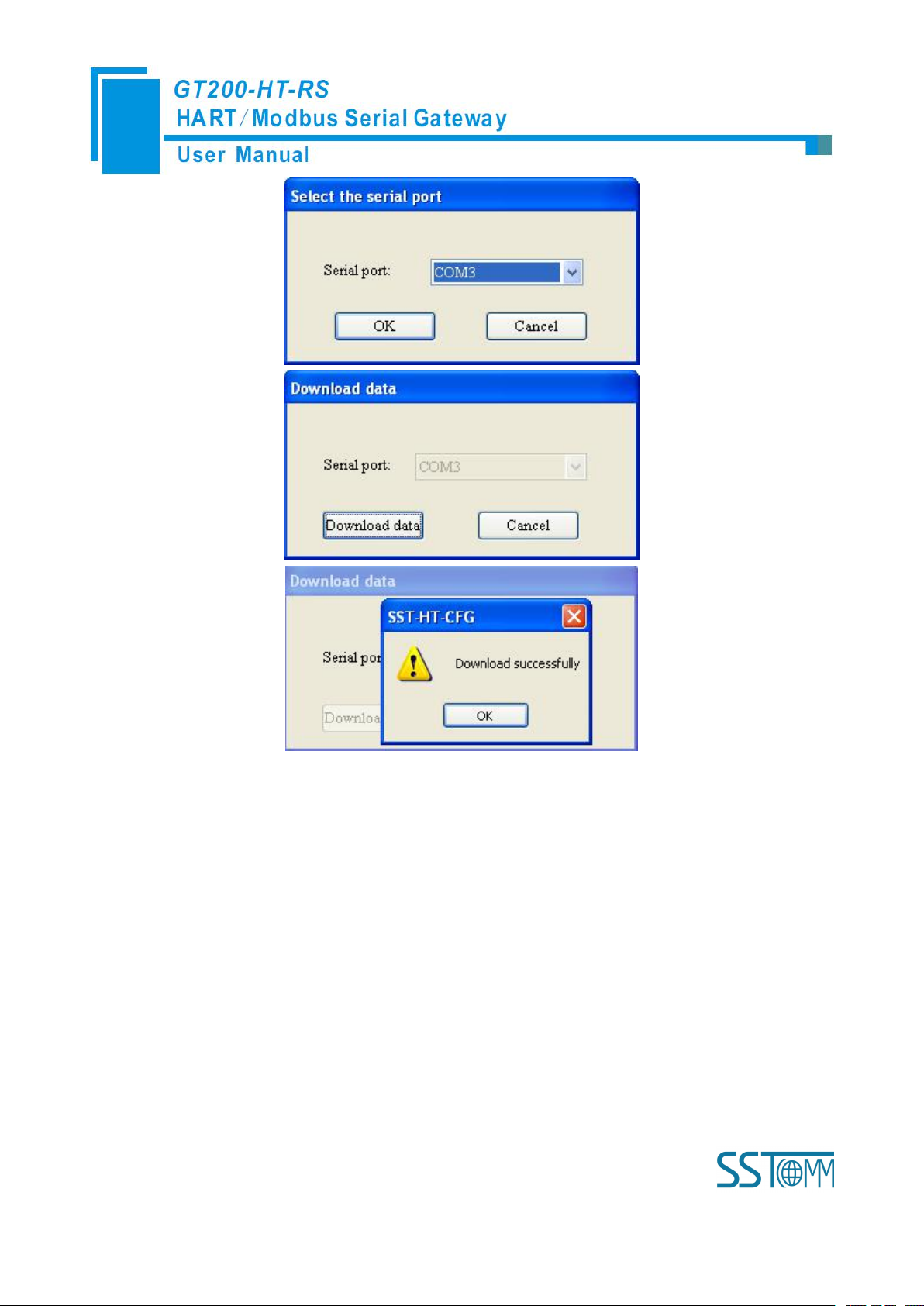
7.Click the tool , in the pop-up dialog box, select the serial port that gateway is connected to the computer,
click OK and then click Download data:
Page 9
WWW.SSTCOMM.COM 9
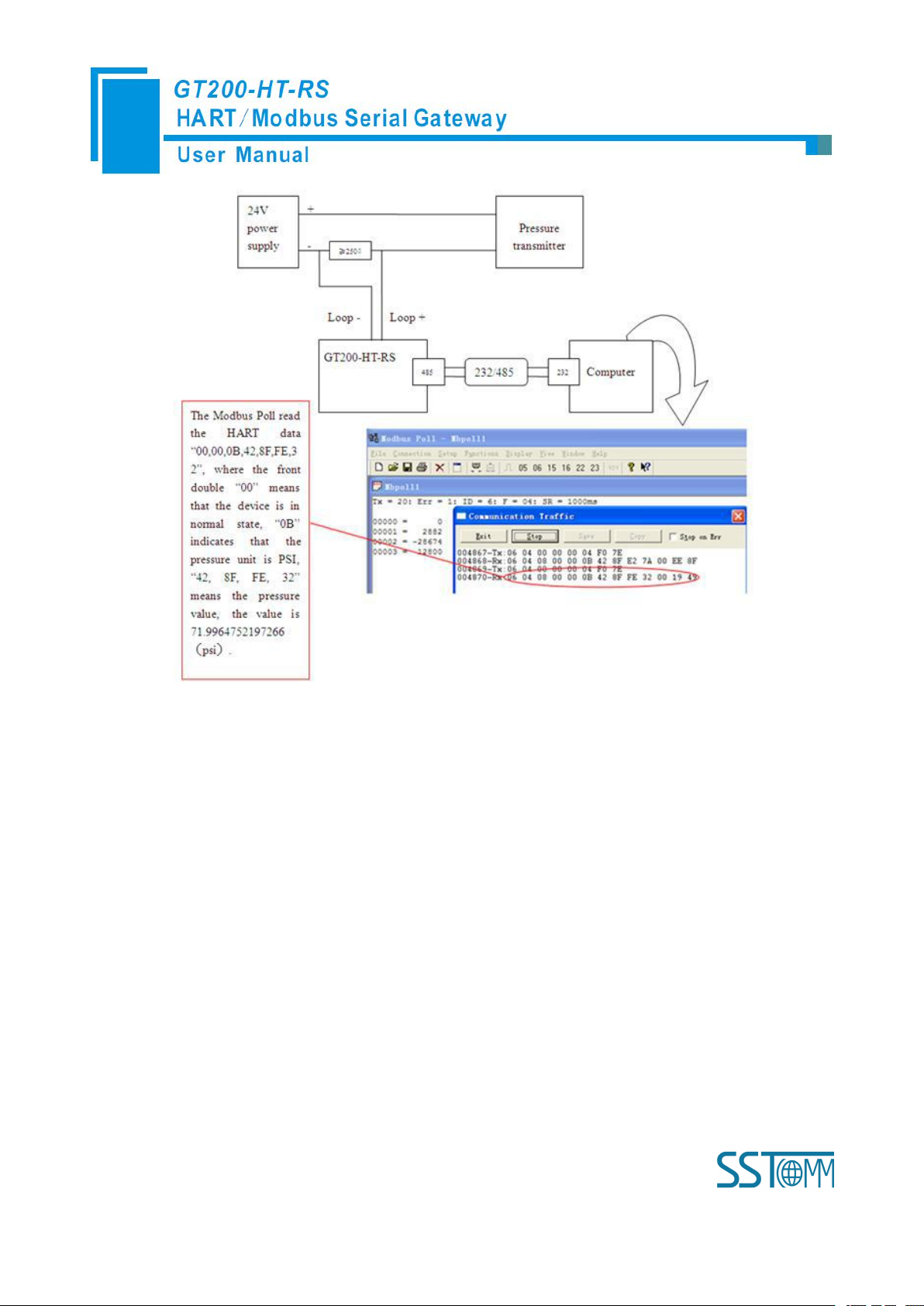
2.2 Function Demo
HART interface of the gateway connects with a 2-wire pressure transmitter with slave address 0, RS-485
interface is connected to the computer through RS-485/RS-232 converter, and computer with configured Modbus
POLL software can simulate to work as a Modbus master, then in data exchange window you can see the main
variable value of the pressure transmitter:
Page 10
WWW.SSTCOMM.COM 10
Page 11

WWW.SSTCOMM.COM 11
3 Hardware Descriptions
HART Interface
LED Display
Power Interface
RS-485/RS-422
RS-232 Interface
DIP Switch
Serial State Indicator
HART State Indicator
Internal/External Sampling
Resistor Switch
Modbus Address Setting Button
Mini USB
3.1 Product Appearance
Note: This picture is for reference only. Product appearance should refer to the real object.
Page 12
WWW.SSTCOMM.COM 12
3.2 Indicators
Indicator location
Indicator
State
State Description
Row 1
TX
Blinking
Serial port data sending
OFF
No data is sending
RX
Blinking
Serial port data receiving
OFF
No data is receiving
Row 2
TX
Blinking
HART Bus data sending
OFF
No data is sending
RX
Blinking
HART Bus data receiving
OFF
No data is receiving
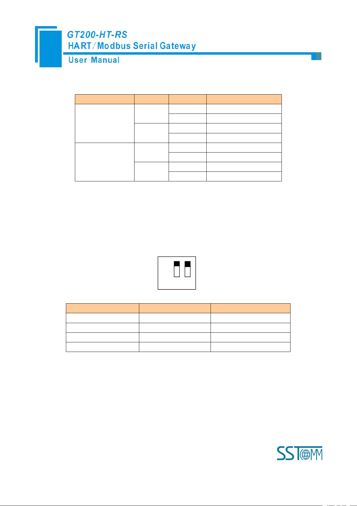
Debugging (bit 1)
Configuration (bit 2)
Description
Off
Off
Run Mode
Off
On
Configuration Mode
On
Off
Debug Mode
On
On
Configuration Mode
Off
On 1 2
3.3 DIP Switch/Button
3.3.1 DIP Switch
The DIP switch is located at the bottom of product, bit 1 is the debug bit and bit 2 is the configuration bit.
Note: ①After re-configuring the switch, you have to restart the GT200-HT-RS to make the settings take
effect! (Power off then Power On)
②Set to the debug mode, it will be compulsory to appoint RS-485 interface as communication
interface, RS-232/USB interface as debugging interface.
③Configuration interface uses the RS-232/USB interface.
Page 13

WWW.SSTCOMM.COM 13
3.3.2 Modbus Address Setting Button
Switch to ON, using the internal
sampling resistor
Switch to OFF, using the external
sampling resistor
Under run mode of the GT200-HT-RS, LED display always displays the address of the current Modbus
address. Quickly press (double-click) the button twice in succession, the high bit starts to flash, and the low bit is
always on, click the button to add 1 to start setting the high bit of Modbus address. Long-press the button for 3
seconds, the high bit is always on, and the low bit starts to flash. Click the button to add 1 to start setting the low
bit of Modbus address. At last, long-press the button again for 3 seconds, the address flashing three times shows
that the address is set successfully. If no button action within ten seconds, GT200-HT-RS exits the status of setting
address and continue to display the original address. The configurable range of Modbus address is 0 to 99
(Decimal).
3.3.3 Internal/External Sampling Resistor Switch
GT200-HT-RS can choose using the internal sampling resistor or external sampling resistor to get the HART
signal. The specification of the internal resistor is 270Ω, 2W. When the power of the sampling resistor is more
than 2W, you must use an external resistor.
Page 14
WWW.SSTCOMM.COM 14
3.4 Interface
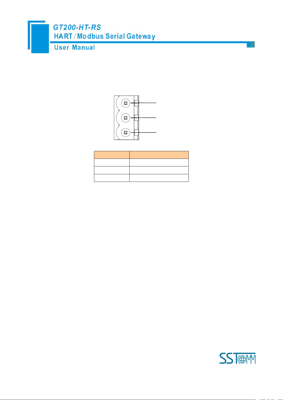
GND
NC
24V+
1
2
3
Pin
Function
1
Power GND
2
NC(Not Connected)
3
24V+, DC Positive 24V
3.4.1 Power Interface
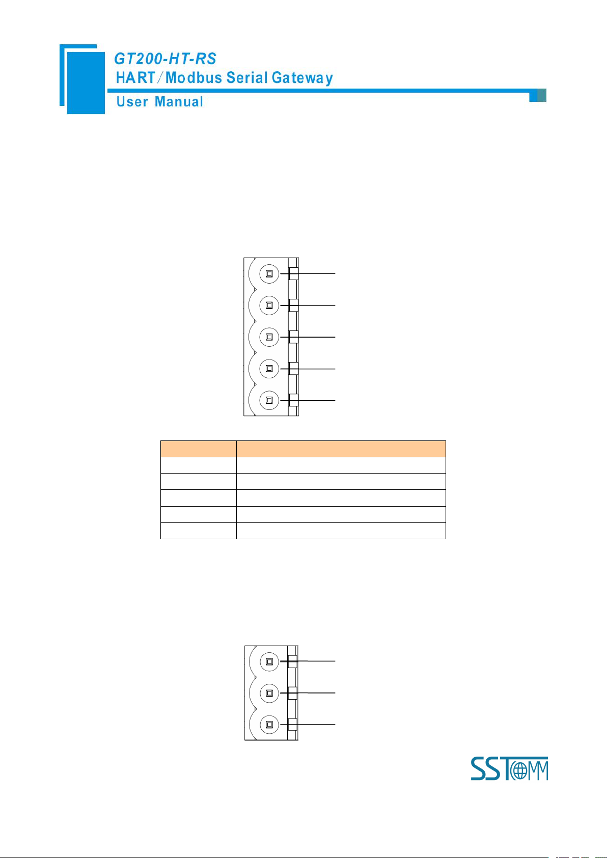
3.4.2 RS-485/RS-422 Interface
The RS-485 interface of GT200-HT-RS is a standard one, and the RS-485 characteristics of the product are
shown as follows:
1. The basic characteristics of RS-485 transmission technology
① Network topology: Linear bus, there are active bus terminal resistors at both sides.
② Transmission rate: 1200 bps~115.2Kbps.
③ Media: Shielded twisted-pair cable and also can cancel the shielding, depending on environmental
conditions (EMC).
④Site number: 32 stations per subsection (without repeater), and can increase up to 127 stations (with
repeater).
⑤Plug connection: 3/5-pin pluggable terminal.
2. The main points on the installation of RS-485 transmission equipment
①All the equipment are connected with RS-485 bus;
Page 15
WWW.SSTCOMM.COM 15
②Each subsection can be connected up to 32 sites;
GND
D-
D+
1
2
3
4
5R-R+
Pin
Function
1
R-, RS-422 Receive Negative
2
R+, RS-422 Receive Positive
3
GND
4
D-, RS-485/RS-422 Transmit Negative
5
D+, RS-485/RS-422Transmit Positive
RXTXGND
1
2
3
③The farthest two end of the bus has a terminal resistor—120Ω 1/2W to ensure reliable operation of the
network.
Serial interface uses 5-pin pluggable open terminal and user can wire it according to the wiring instructions
on the panel.
5-pin terminal:
3.4.3 RS-232 Interface
RS-232 interface uses one 3-pin pluggable open terminal, and its pin description is shown as follows:
Page 16
WWW.SSTCOMM.COM 16
Pin
Function
1
RX, Connect RS-232's RX of user device
2
TX, Connect RS-232's TX of user device
3
GND, Connect RS-232's GND of user
device
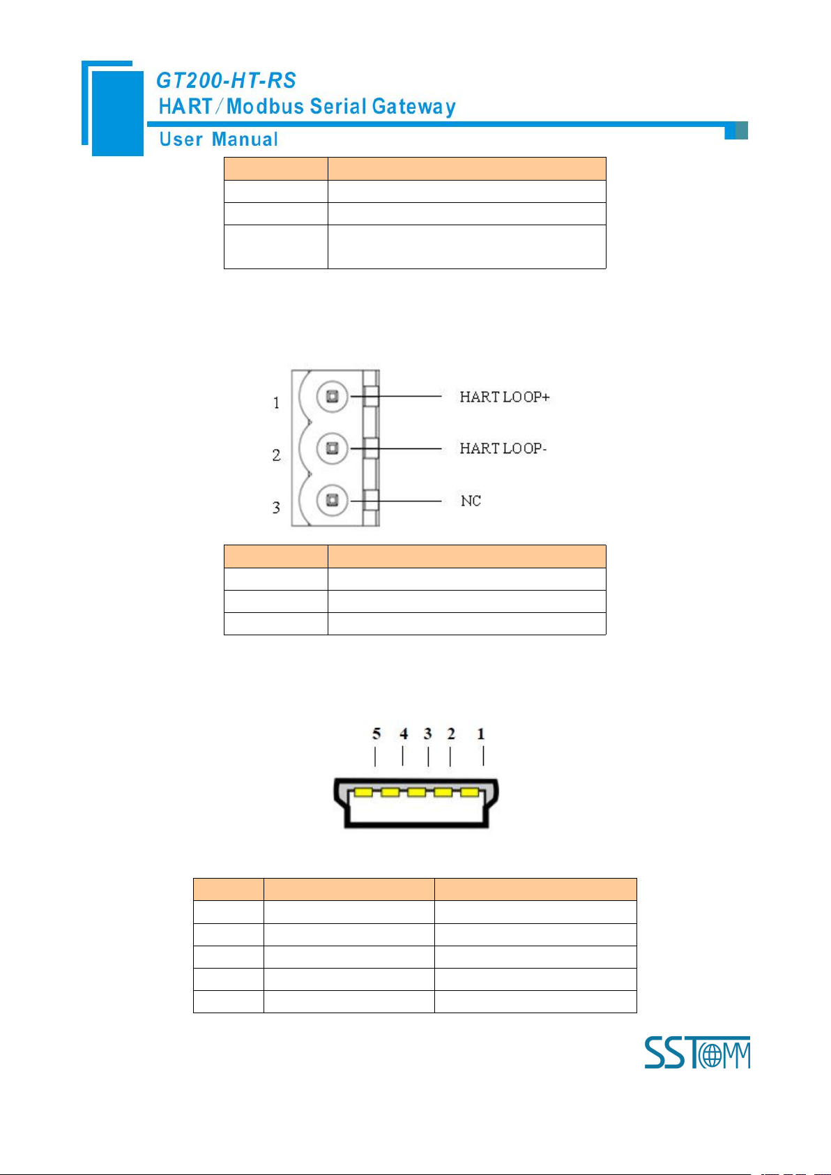
3.4.4 HART Interface
Pin
Function
1
Connect HART signal positive
2
Connect HART signal negative
3
NC
Pin
Name
Function
1
VBUS
+5V
2D-Data negative
3D+Data positive
4
IN
NC
5
GND
Signal Ground
3.4.5 Mini B Type USB
Mini B type USB interface is defined as below:
Page 17

WWW.SSTCOMM.COM 17
3.5 Topology of GT200-HT-RS and Fieldbus Devices
Page 18

WWW.SSTCOMM.COM 18
Note: 1. Some HART slave instrument need to perform self-test and other internal work when power is on, they
may not start HART communication, then gateway cannot receive the response data of the instrument right now. It
is recommended the HART slave instrument and gateway uses separate power supply so that the gateway can
immediately establish communication with instrument.
2. When configuring HART commands in the software SST-HT-CFG, the commands need to be
configured according to the actual demands. To improve the speed of bus communication, it is recommended not
to configure the empty node (in fact, not connected to the node) and empty commands (the actual unnecessary
commands).
Page 19
WWW.SSTCOMM.COM 19
4 Software Instructions
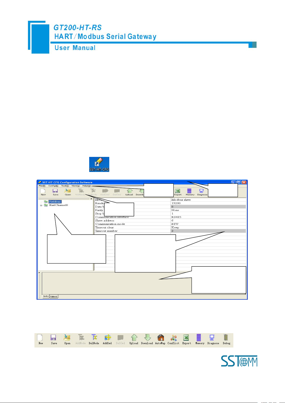
Network Settings interface:
Contains Fieldbus and the
connection object
Menu Bar
Tool Bar
Title Bar
Parameter Settings interface:
Contains modifiable part
(white) and unmodifiable part
(grey)
Comment field: Explain
the function of the
configuration options
4.1 Software Interface Description
SST-HT-CFG is configuring software based on Windows platform, and used to configure HART series
products.
The following describes how to use the software SST-HT-CFG to configure the product GT200-HT-RS. You
may also check the software user manual to get detailed usage.
Double-click on the icon to enter the main interface of software:
Tool Bar:
Toolbar interface shown as follow:
Page 20
WWW.SSTCOMM.COM 20
The function from left to right is: New, Save, Open, AddNode, DelNode, AddCmd, DelCmd, Upload,
Download, AutoMap, Conflict, Export, Memory, Diagnose and Debug.
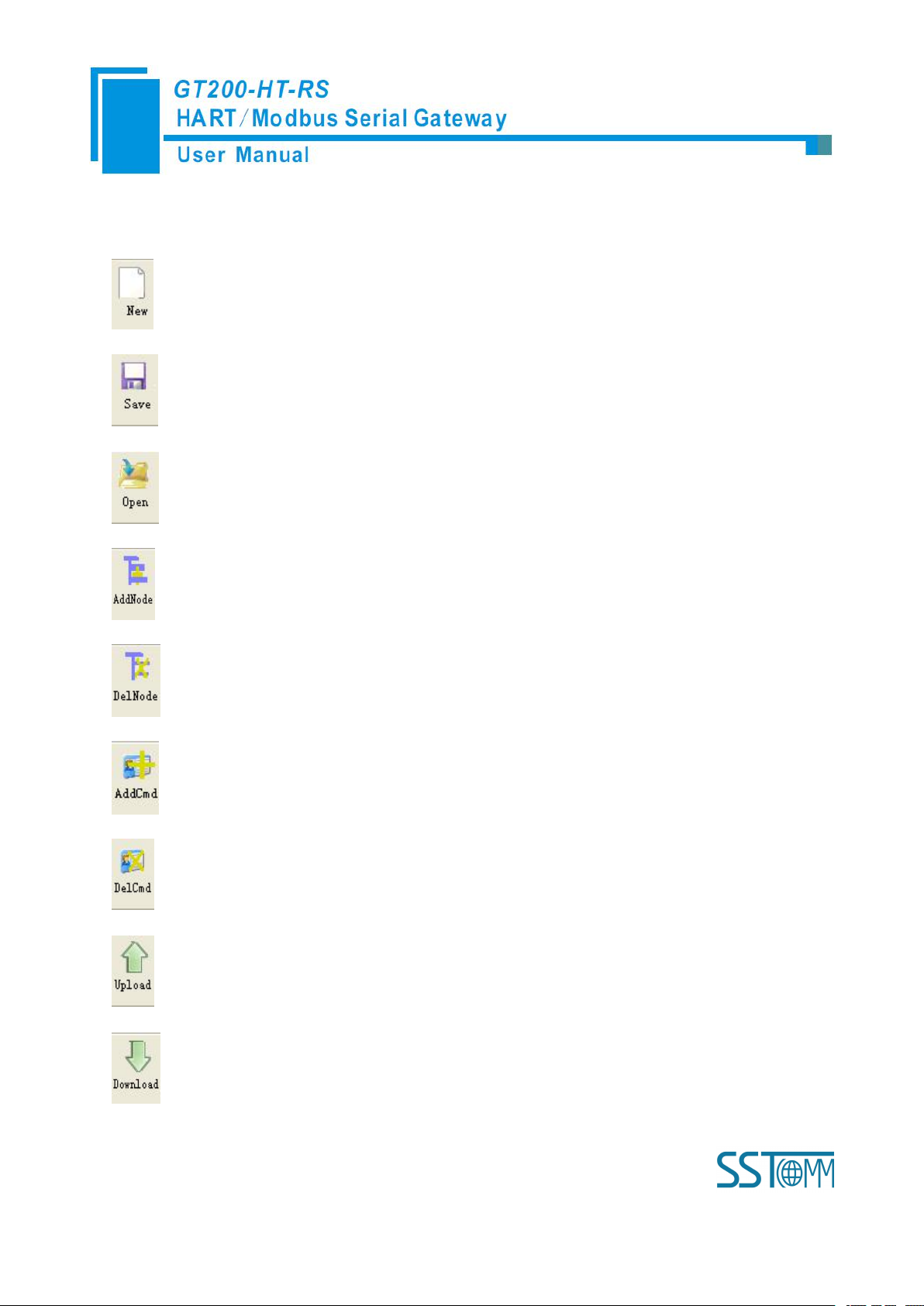
New: Create a new configuration file
Save: Save the configuration file
Open: Open the configuration file
AddNode: Add a HART slave node
DelNode: Delete a HART slave node
AddCmd: Add a HART command
DelCmd: Delete a HART command
Upload: Read the configuration information from the module and shown in the software
Download: Download the configuration file to the gateway
Page 21
WWW.SSTCOMM.COM 21
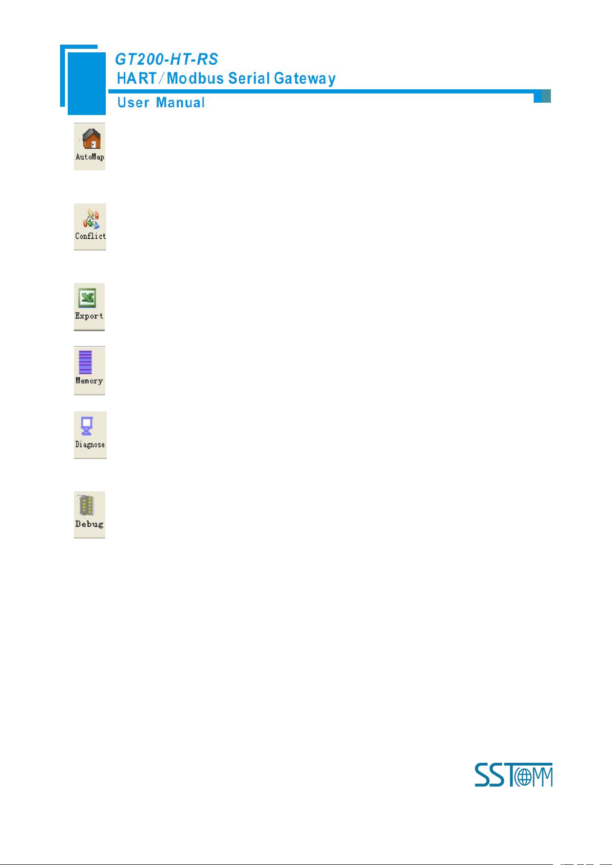
AutoMap: Used to automatically calculate the mapped memory address without confliction by each
command
Conflict: To check whether there are some conflicts with configured commands in the gateway
memory data buffer
Export: Output current configuration to the local hard disk and saved as Excel spreadsheet form
Memory: Show the data exchange inside of the gateway
Diagnose: through this function could analyze operating condition of fieldbus device; also it can finish
some certain analysis
Debug: through this function could send any request frame to Hart fieldbus and show the response
information received in HART, convenient to debug
4.2 Software Functional Specifications
4.2.1 Connect with the Hardware
Put the gateway configuration switch to “ON”, use a serial port line to connect the gateway RS-232 port and
that of computer or use USB cable line to connect gateway’s USB port and computer . Power on the gateway and
its LED display displaying “CF” indicates it is in the configuration mode.
Page 22
WWW.SSTCOMM.COM 22
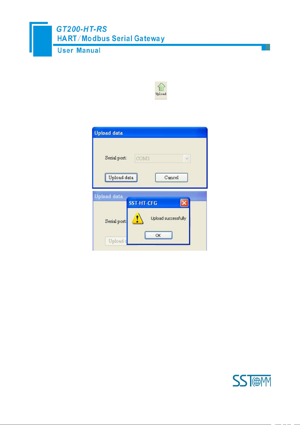
4.2.2 Upload configuration
Open the software “SST-HT-CFG”, Click on the icon , Select the computer port connected to the
gateway and then click “upload data”, If it shows “upload successfully”, which indicates that configuration file
had been uploaded to the SST-HT-CFG.
4.2.3 Configure the Fieldbus
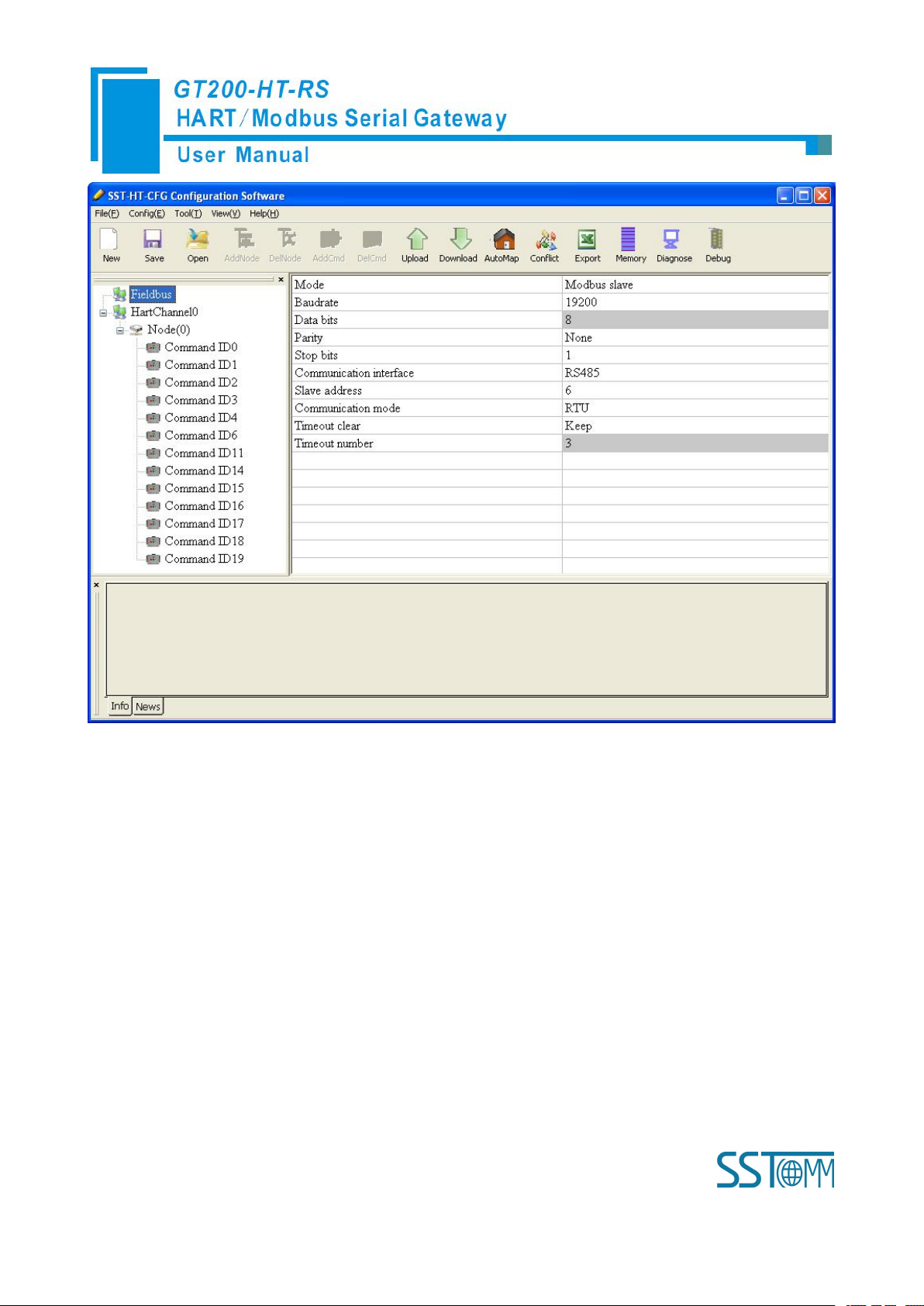
4.2.3.1 Configure the fieldbus as Modbus slave
If you want to use the functionality of Modbus slave, click the “Fieldbus” in the tree view, select mode as
“Modbus slave” in the right configuration plate, and then press ENTER to confirm, you will see the interface as
below:
Page 23
WWW.SSTCOMM.COM 23
In this interface you can set the parameters as shown:
Baud rate: 300, 600, 1200, 2400, 4800, 9600, 19200, 38400, 57600, 115200bps
Data bits: 8
Parity: None, Odd, Even, Mark, Space optional
Stop bits: 1, 2
Communication mode: RTU, ASCII
Slave address: 0~247
Communication interface: RS-485, RS-232 optional. When the serial need to communicate with RS-422,
please choose “RS-485”
Timeout clear: When the HART commands exceed the no-reply times, whether or not to clear the HART
input data buffer
Page 24
WWW.SSTCOMM.COM 24
Timeout number: set the timeout/clear times
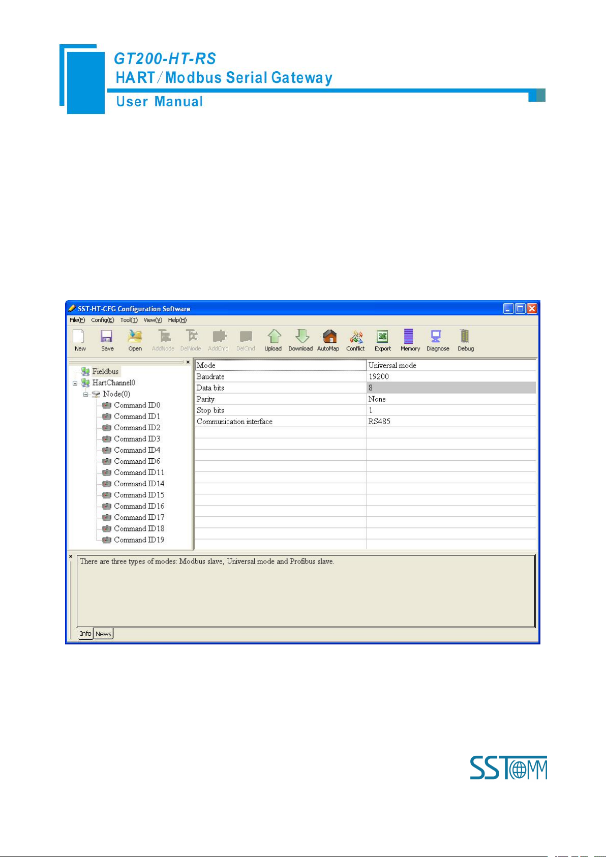
4.2.3.2 Configure the fieldbus as universal mode
The universal mode (transparent transmission mode) means that we can send HART frame directly through
serial port (RS-232/RS-485/RS-422), meantime gateway also will send out the data received from HART bus
through serial port. In this process, the data don’t change.
Click the “Fieldbus” in the tree view, select mode “Universal mode” in the right configuration plate, and then
press ENTER to confirm, you will see the interface as below:
The range and meaning of general mode are the same as “Modbus Slave”.
Page 25
WWW.SSTCOMM.COM 25
4.2.4 Configure the HART Fieldbus
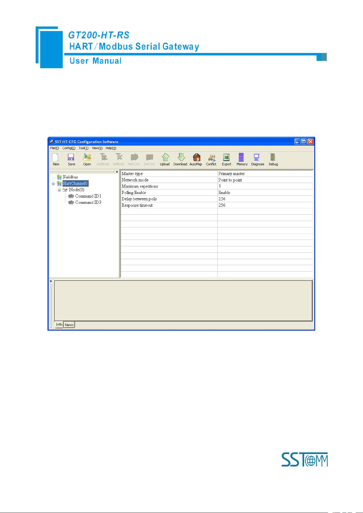
4.2.4.1 Set the Parameters of HART Channel
Click the HartChannel0 in the tree view, in the right place will show the configuration plate:
Master type: Primary master, Secondary master
Network mode: Select the networks link as single or multiple points, in the single point the gateway can only
communicate with the slave device whose address is 0;
Maximum repetitions: 0~5
Polling Enable: Enable, Disable
Delay between polls: 256~65535ms
Response timeout: 256~65535ms
Page 26

WWW.SSTCOMM.COM 26
4.2.4.2 Add Slave Nodes
Select the”HartChannel0”, Right click the mouse and click “Add Node”.
Click the added node, set slave address in the right configuration plate, and please notice that HART channel
can only be equipped with one slave node when configured in the single point mode.
Note: When configured node numbers are more than the actual connected devices, the redundant node will
lead to the longer time of polling circle; so, it is recommended that configured node numbers should be the same
as actual devices.
4.2.4.3 Add HART Commands
Select the “Node (x)”, Right click the mouse and click “Add Command”.
Page 27

WWW.SSTCOMM.COM 27
Choose the command you want in the popup menu, and then click “OK” to exit:
Note: the same command can only be configured once in one node.
4.2.4.4 Configure HART Commands
Click the command number in the tree view; you will see the configuration plate in the right place:
Page 28

WWW.SSTCOMM.COM 28
Configuration Mode: basic and advanced optional, “basic” is shown as above, “advanced” configuration can
Change-of-state output: Execute this command once s data buffer of HART changes
Polling output: This order is put in the polling list, executed periodically
Initialization output: Execute the command only once when power is on
Disable output: the command will not be sent.
refer to chapter 4.2.4.7;
Mode of outputting command: You can use the execution way of the command, change-of-state, polling
output, Initialization output and disable output optional;
Memory starting address of sending data: Set the memory starting address of output data by this command,
the range is 3000~3999;
Modbus register starting address of sending data: the property is automatically calculated by gateway, used
for register addressing;
Sending data length (BYTE): used to set the length of output data by this command;
Sending data length (WORD): the property is automatically calculated by gateway, used for user checking
output data length, 1 word=2 byte;
Memory starting address of receiving data: set the memory address of input data by this command. Response
Page 29

WWW.SSTCOMM.COM 29
data only includes data area of HART frame;
Modbus register starting address of receiving data: the property is automatically calculated by gateway, used
for register addressing;
Receiving data length (BYTE): set the length of input data by this command;
Receiving data length (WORD): the property is automatically calculated by gateway, used for user checking
output data length conveniently, 1 word=2 byte;
Command index: the property is automatically calculated by the configuration software, it indicates the index
in the configured command list this command belongs to.
4.2.4.5 Delete Commands
Select the command need to be deleted, Right click the mouse and click “Delete Command”. Through the
menu command can also be the same action.
4.2.4.6 Delete Nodes
Select the node needed to be deleted, Right click the mouse and click “Delete Node”. Through the menu
command can also be the same action.
4.2.4.7 Advanced Options to Configure Slave Commands
When using HART command configuration, sometimes users want to get one part data of one command. For
example, No.1 HART command. The float value of main variable is only needed, no need to get unit of main
variable, this is why advanced option exists. Advanced options is actually the execution of “segment mapping
function”, it cut the response data of HART command and get the segment data. Users can get any part data they
want. Below is the interface of Advanced Options:
Page 30

WWW.SSTCOMM.COM 30
This interface details is described in chapter 4.2.4.4, so here we don’t describe it. The below is the example
of No.3 HART command, to show how to use “Segment Mapping” function, we can see one “configuration”
button after the “receive data project configuration” option, click it:
There are many parts in “Bytes”. For example, “Command Status” means the communication status and
relevant code of HART response command, “Byte0-3” means byte 0 to 3 of data area of HART response
Page 31

WWW.SSTCOMM.COM 31
command, and so on.
In the above example, click “Byte5-8” will show the Primary Variable in the left bottom area. Other column
have the relevant explanation.
First to explain the “Mapped Address”:
Bytes: response bytes of “Response Data”;
Memory Address: assigned memory address which this byte is located in memory buffer area of
GT200-HT-EI;
Modbus register address: the relevant Modbus register address of “Memory Address”; Note: this address is
not a single address, that is the same memory area which it occupied.
Byte swap: there are two options, “no swap” and “register swap”, swap option is only valid to float type data.
When using “no swap”, the byte order is byte1, byte2, byte3 and byte4. After using “register swap”, the byte order
will be byte3, byte4, byte1 and byte2. For example, the original data is 0x12345678, it will be 0x56781234 after
using “register swap”.
Choose “Byte0-3” and “Byte5-8”, click auto mapping, as shown below:
Close the dialog box, download the configuration into GT200-HT-RS.
Others are the same with “Basic Mode”.
Page 32
WWW.SSTCOMM.COM 32
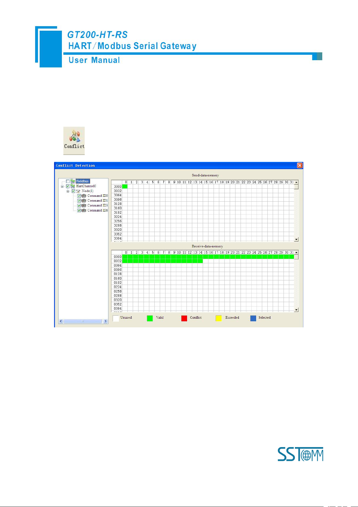
4.2.5 Conflict Detection
Conflict detection is used to check the distribution condition of the input and output data of all commands
stored in the memory.
Click icon will show the conflict detection interface as follow:
The left side is configuration commands, the right side is data memory address including receive data storage
address and send data storage. Upper side is memory distribution of the HART’s sending data; lower side is
memory distribution of the HART’s receiving data. When one memory unit is configured with two commands or
more, the memory unit will display red color. When the distributed memory exceeds the defined scale of gateway,
the exceeding part will display yellow color. White color area shows the usable memory. Green color area
indicates occupied memory. Clicking one command, the distribution chart shown in blue will show the storage
location of input/output data.
Page 33
WWW.SSTCOMM.COM 33
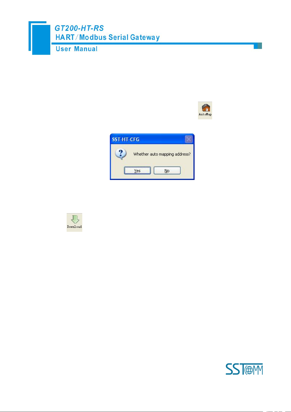
4.2.6 AutoMap
1. Set the DIP switch’s debug bit to ON state and the configuration bit to OFF state, restart the
2. Use a serial port line to connect the GT200-HT-RS’s RS-232 port and computer RS-232 serial port
Automap will automatically distribute the memory with no conflict according to the input/output bytes
number by users’ commands.
You should set the correct input/output bytes for each commands, then click label, select “yes” in the
popup menu.
4.2.7 Download Configuration
Click the icon ; it will download the configuration into the gateway.
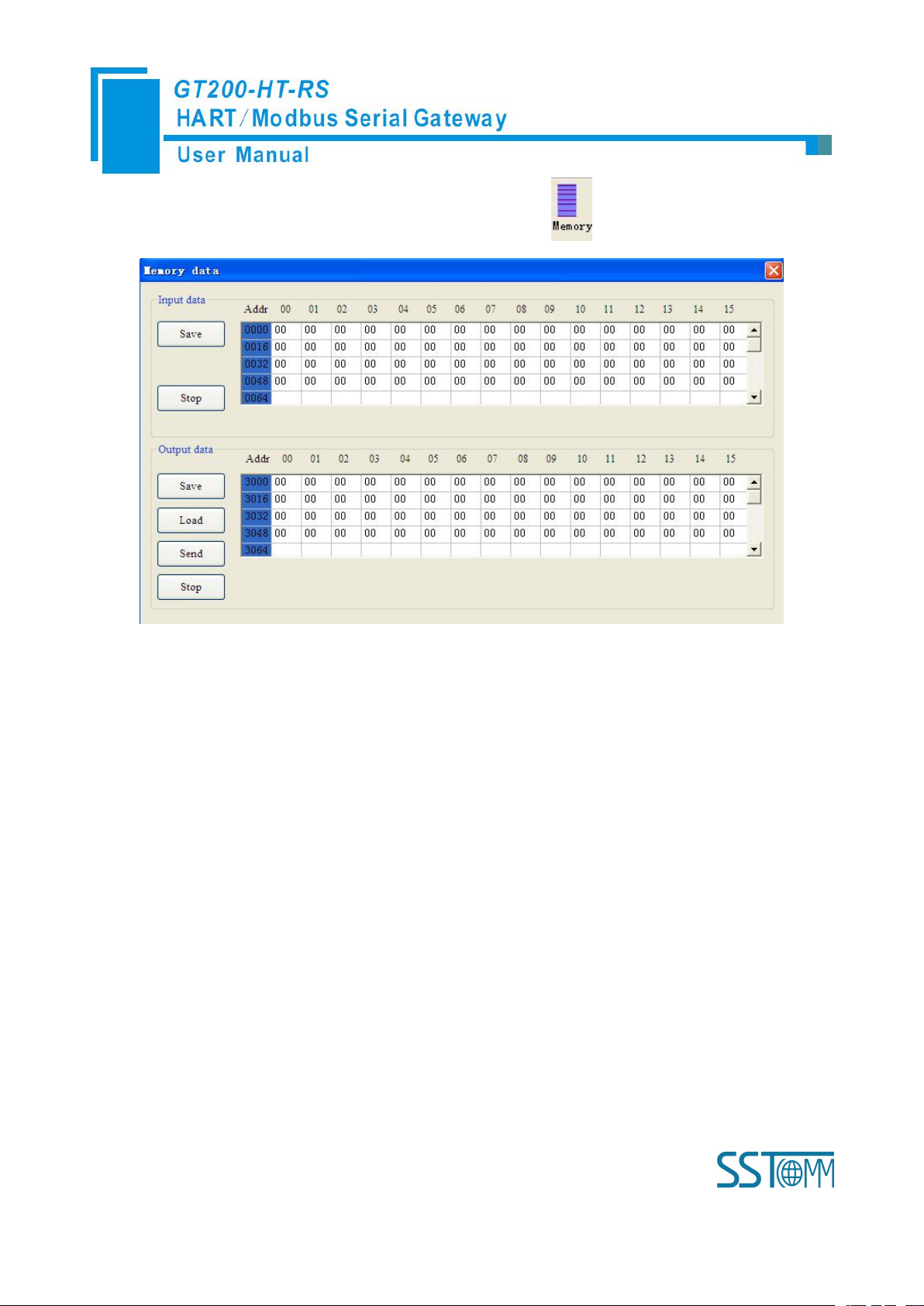
4.2.8 Memory Data Display
Show the data exchange inside of the gateway, users can use this function to debug the HART fieldbus in the
absence of the Modbus master station. Steps are as follows:
gateway. GT200-HT-RS is in the debug mode.
or use USB way to connect it, open the software “SST-HT-CFG”, Click “Config—Serial
Connection”, Select the correct serial port
Page 34
WWW.SSTCOMM.COM 34
3. Click “Tool—Show Memory Data” or click on the icon , Interface is as follows:
As is shown in the table, upper table shows the memory distribution of HART input data, lower table shows
1. Set the DIP switch’s debug bit to ON state and the configuration bit to OFF state, back online.
2. Use a serial port line to connect the GT200-HT-RS’s RS-232 port and computer RS-232 serial port or
the output data. When you need to change the output data, click the “stop” button firstly, then change the related
data or load the already saved data table, at last, click the “sending data”.
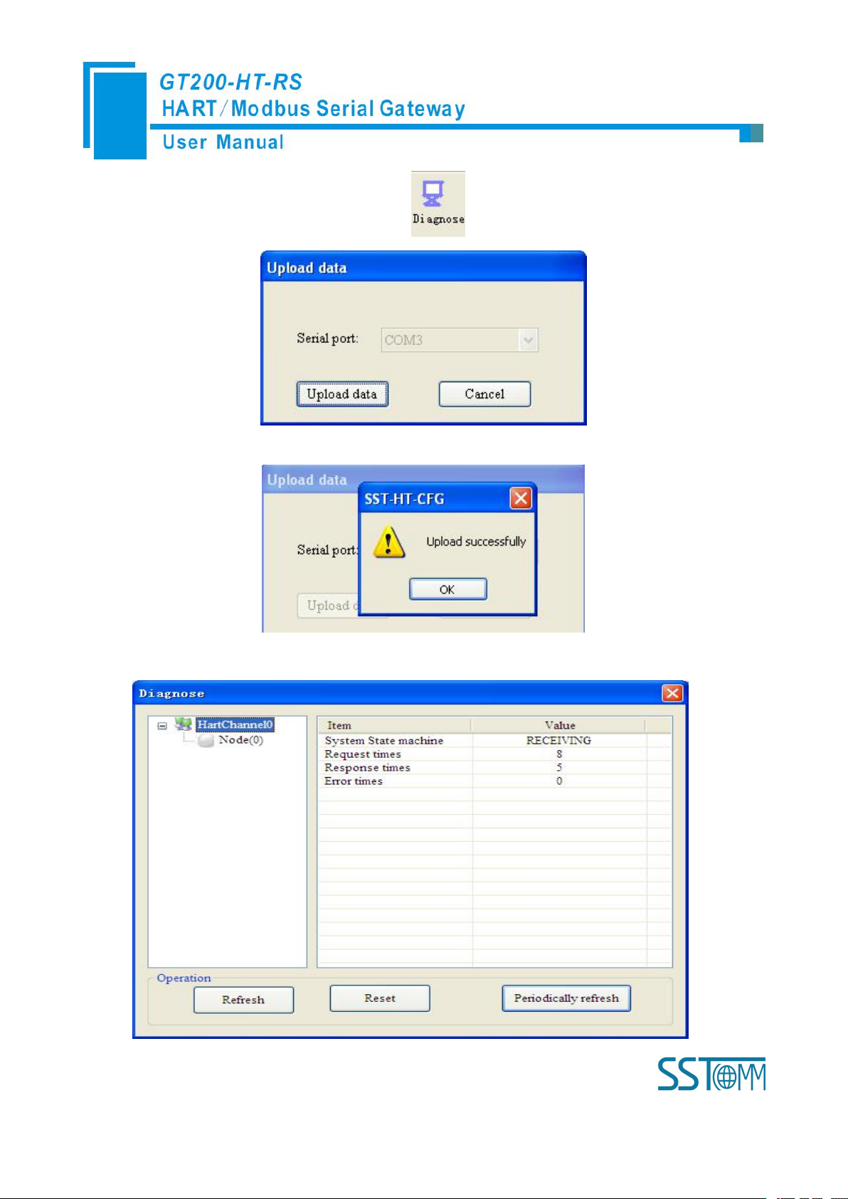
4.2.9 Diagnose
Through this function users will know which device is not communicating, execution condition of configured
commands, data transmit of gateway and displays of certain command, operating steps are as follows:
GT200-HT-RS is in the debug mode.
use USB way to connect it, open the software “SST-HT-CFG”, Click “Config—Serial Connection”,
Select the correct serial port
Page 35
WWW.SSTCOMM.COM 35
3. Click “Tool—Diagnose” or click on the icon , Interface is as follows:
4. Click “Upload data” will see a picture as below:
5. Click “OK” button to get in the interface of diagnose:
Page 36
WWW.SSTCOMM.COM 36
Click on “HartChannel0” in this interface, it will show the status of HART fieldbus part in the right place,
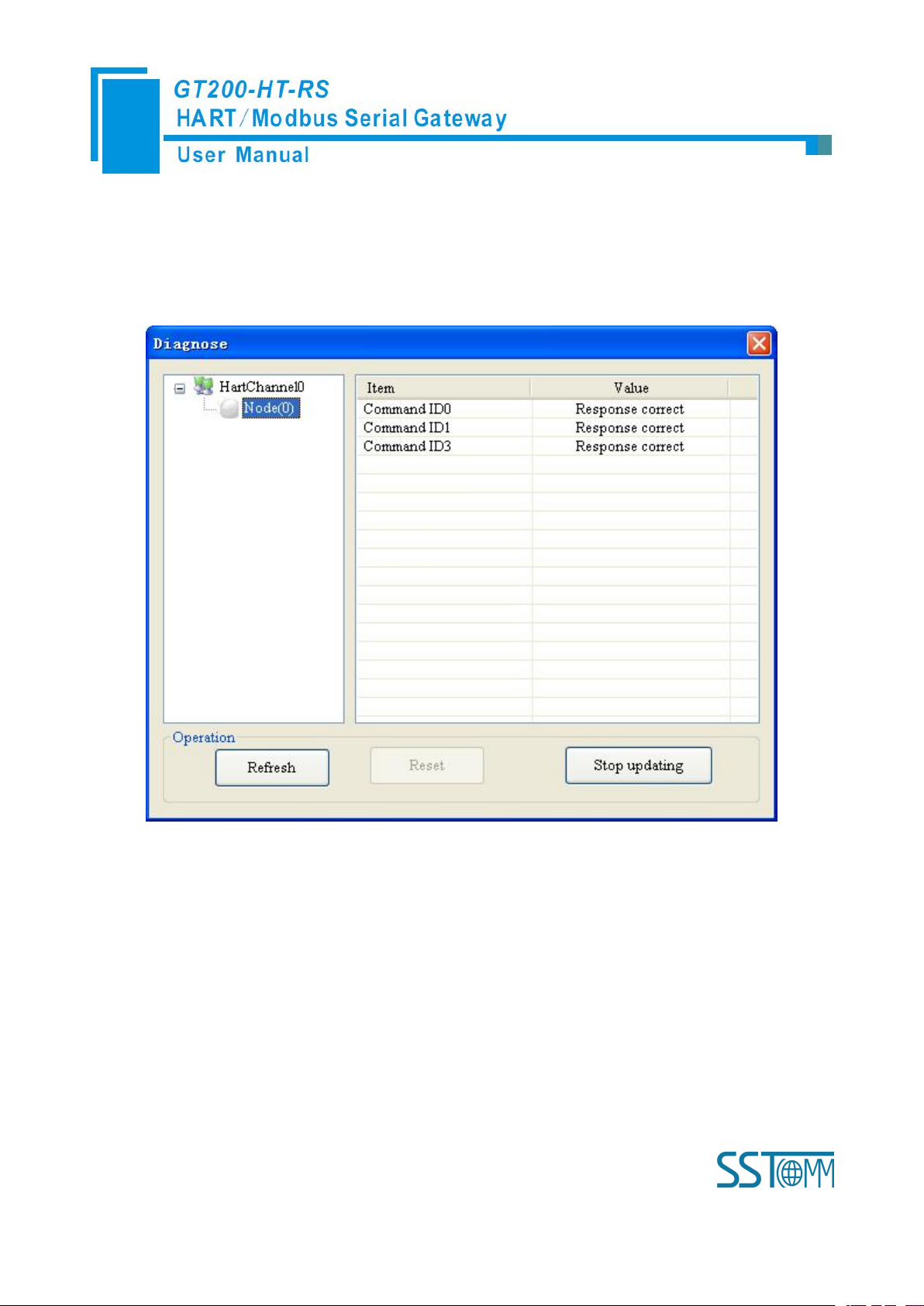
6. Click Node(x), it is shown as below:
7. Double click command 0, 1, 2, 3, 6, 11, 12, 13, 14, 15, 16, 17, 18, 19 will show their command
press “Refresh” button will update the data once, click on “Periodically refresh”, the software will update the data
every 500ms.
It shows the response status of configured commands.
Click “Refresh” will fresh these command status, “Periodically refresh” will fresh command status once.
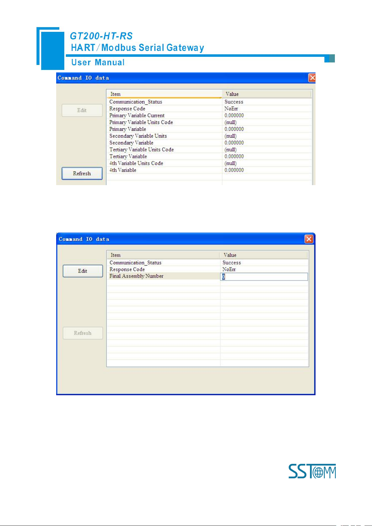
information, command 6, 17, 18 and 19 can start data input.
Page 37
WWW.SSTCOMM.COM 37
Click the“Refresh” button will update the data, click the “Edit” button doesn’t work in the Read-only
command.
Double click “CMD19” will show the window as below:
Click the value or attribute you want to change, like “Final Assembly Number”, change relevant values, and
click “Modify” can execute this operation of write command.
Page 38
WWW.SSTCOMM.COM 38
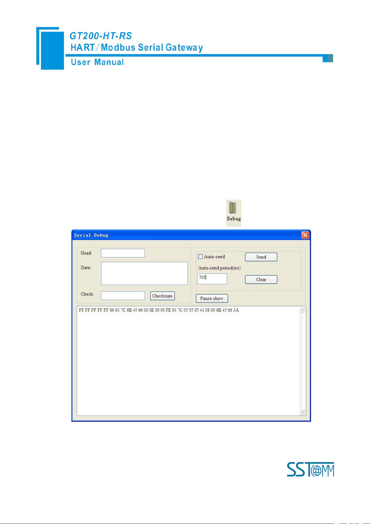
4.2.10 Serial Debug
1. Set the DIP switch’s debug bit to ON state and the configuration bit to OFF state, restart the gateway.
2. Use a serial port line to connect the GT200-HT-RS’s RS-232 port and computer RS-232 serial port or
3. Click “Tool—Serial Debugging Assistant” or click on the icon , Interface is as follows:
Through this function could send any request message to Hart instruments and record the response
information. Steps are as follows:
Now GT200-HT-RS is in the debug mode.
use USB way to connect it, open the software “SST-HT-CFG”, Click “Config—Serial Connection”,
Select the correct serial port
In this interface, click “Auto-send” or “Send” will combine data head, data, and check code into one frame
and send out it. The data that the gateway received from HART fieldbus will be shown in the blank place below.
Page 39

WWW.SSTCOMM.COM 39
The “Checksum” button only checks part of the data. Here is an example.
In this example, command ID0 is composed of data head, data and check code. It uses short address; when
you click “Send”, you will get the response data.
Note: Under this function, gateway will stop to execute the configured command; Turn off this function,
gateway will return to execute the configured command.
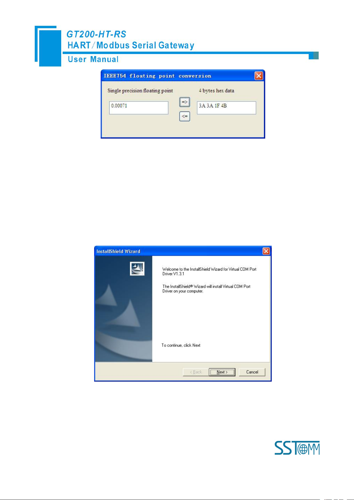
4.2.11 Useful Tools
In the “Tools” menu, there are two useful tools: They are used to finish data conversion.
PACKED ASCII conversion:
IEEE 754 conversion:
Page 40
WWW.SSTCOMM.COM 40
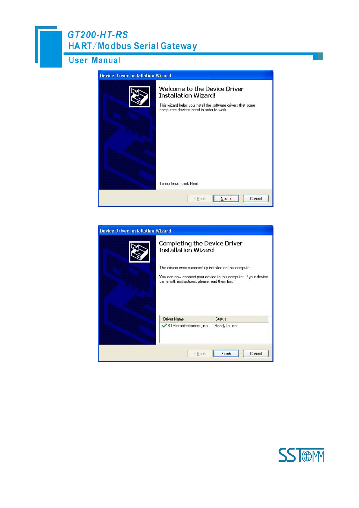
4.2.12 Use USB Port
For now, USB port is only used for debugging and configuration. Its function is the same as RS-232 under
configuration and debug. After installing USB driver, this USB driver will generate a virtual COM port on PC,
GT200-HT-RS can communicate with PC through this virtual COM port. Please ensure that this USB driver is
installed before using this function.
Installing driver, as show below:
Click “Next”,
Page 41
WWW.SSTCOMM.COM 41
Click “Next”,
Click “Finish”, to finish the installation of USB driver.
How to find this virtual COM port? Use USB cable line to connect GT200-HT-RS and PC, set bit 2 of DIP
switch to ON, and power on the product. Open the “Computer Management” of PC, you will find there is one new
COM port under “Port (COM&LPT), as shown “STMicroelectronics Virtual COM Port (COM3), that is the
virtual COM Port:
Page 42

WWW.SSTCOMM.COM 42
Noted: Different computer, the serial number will be different.
Open SST-HT-CFG software, click “Config” and choose Serial port, here choose COM3, as shown below:
After choosing serial port, click “Upload” on the toolbar,
Page 43

WWW.SSTCOMM.COM 43
After clicking Upload data, it will show uploading succeeded:
Page 44

WWW.SSTCOMM.COM 44
Page 45

WWW.SSTCOMM.COM 45
5 Working Principle
Gateway
memory
address
Corresponding
Modbus register
address
Description
Read-only part
0-1599
0-799
The HART data input area
1600-1619
800-809
Device 0_cmd0 data
1620-1639
810-819
Device 1_cmd0 data
……
……
……Device 15_cmd0 data
1920
960H
Gateway status
1921
960L
Send times of Gateway’s HART port
1922
961H
Receive times of Gateway’s HART port
1923
961L
HART communication error times
1924-1943
962-971
Reserved
1944
972H
Device 0_cmd0’s response status
1945
972L
Device 1_cmd0’s response status
……
……
……Device15 _cmd0’s response status
1960-2119
980-1059
The response status of the user command
2120-2391
1060-1195
Reserved
2392
1196H
Universal receive label
2393
1196L
Universal receive Error Counter
2394-2395
1197
Universal receive data length
2396-2695
1198-1347
Universal receive data
2696-2999
Reserved
Readable
and
writable
part
3000-3999
0000-0499
The HART data output area
4000
0500H
Reset to send, receive, error counter
Inside the gateway it opens up a length of 5000 bytes of memory as the data exchange of input and output
buffers. Memory of 0 to 2999 acts as the storage area of the HART input data and device status. Memory of 3000
to 4999 acts as storage area of the HART output data and control variables. The specific assignment shown in the
table below:
Page 46

WWW.SSTCOMM.COM 46
4001
0500L
Polling enabled
4002
0501H
Trigger label
4003
0501L
Trigger command number
4004-4269
0502-0634
Reserved
4270
0635H
Universal send label
4271
0635L
Universal mode enabled
4272-4273
0636
Universal send data length
4274-4573
0637-0786
Universal to send data
The HART data input area: Store the data that HART slave device sends to gateway.
The HART data output area: Store the data that the gateway sends to the HART slave device.
Device 0_cmd0~ Device 15_cmd0: When operating a slave command for the first time, the gateway internal
will automatically execute the No. 0 command to obtain the device information (to obtain the long address).
Gateway status: The gateway status indicates what the gateway state is in the HART network, defined as:
Send times of HART port on gateway: The HART send counter
Receive times of HART port on gateway: The HART receive counter
HART communication error times: The HART Receive error counter
The response status of Device 0_cmd0~ Device 15_cmd0: Show that the response status of the internal
The response status of user command: Show that the response status of the user command
The response data of this internal command is stored in this area.
0---- No HART communication
1----sending
2---- Waiting for a response
3---- Handling a response
command
Command state is defined:
0---- Not executed
1---- Correct response
2---- Parity error
3---- No answer
Page 47

WWW.SSTCOMM.COM 47
4---- Error defined in agreement
Universal Receive label: The receive label under the universal mode, this value which changes one time
Universal receive data length: Indicating the received data length under the universal mode
Universal Receive Error Counter: Indicate the universal receive error number
Universal receive data: Store the received data at HART side under the universal mode
Reset send, receive, error counter: The gateway’s control signal, when the value of memory changes,
Polling is enabled: This bit is readable and writable, writing 1 enables the polling output, writing 0 disables
Trigger label: Change the value will result in a trigger operation
Trigger command number: Command number executed by trigger operation
Universal mode enabled: The value of 1 indicates a universal transfer function is enabled, otherwise disables
Universal send label: The send label under the universal mode, this value changes in time will lead to send a
The universal send data length: The length of send data under the universal mode
Universal to send data: Data needs to send under the universal mode
5---- Not connected
indicates that HART end receives a HART frame
gateway causes all the counter to 0
polling output; Reading 1 indicates that the polling state is enabled, 0 indicates that the polling is in the
disabled state
universal transport function
HART frame
Page 48
WWW.SSTCOMM.COM 48
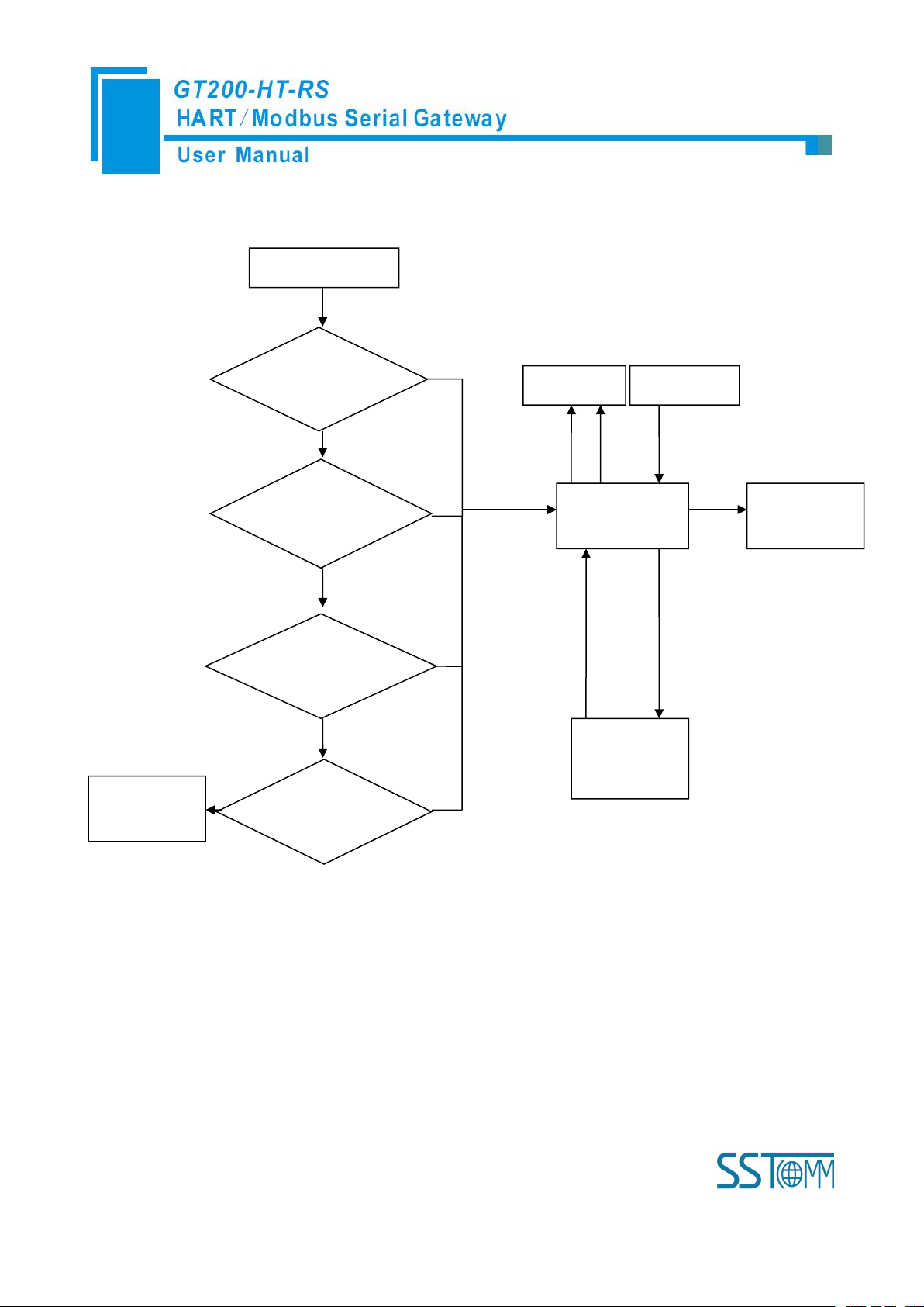
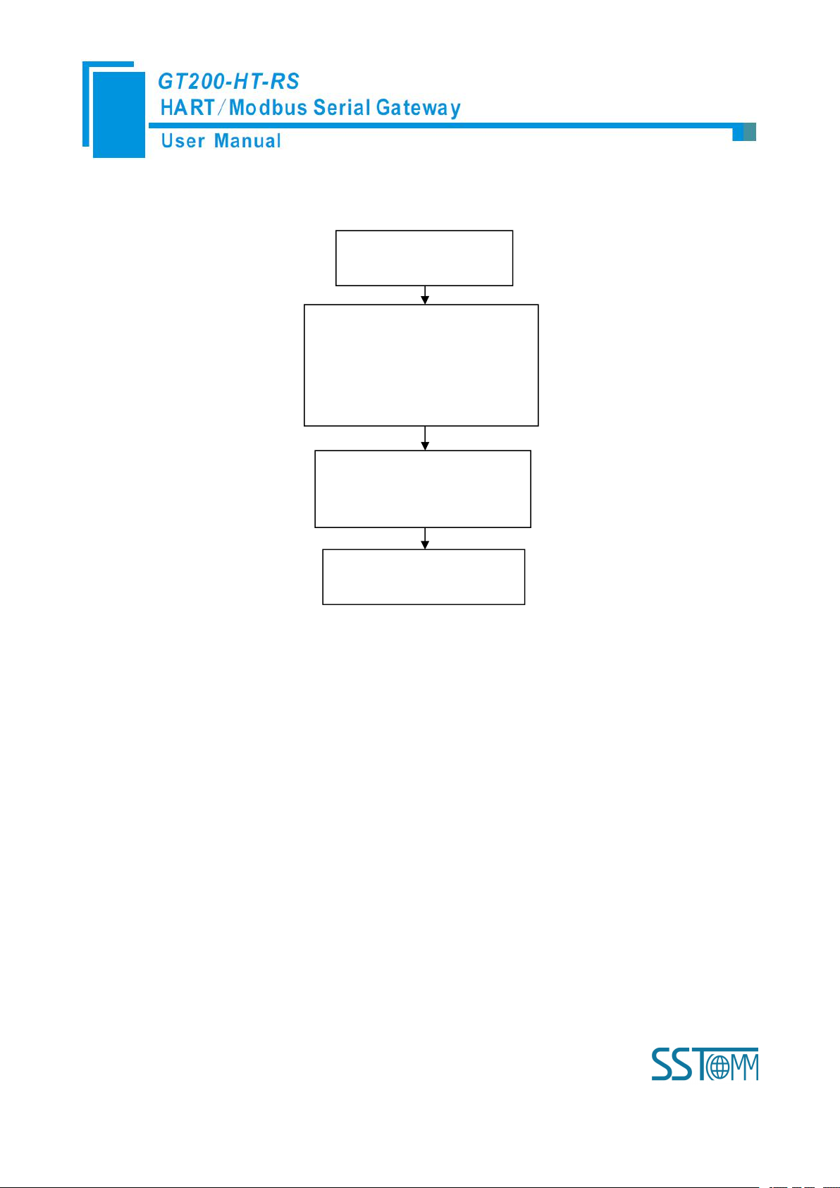
5.1 Flowchart of Executing One HART Command
Initialization
output
Satisfy the
polling output
Satisfy Change
of state output
Meet the
trigger output
Execute
command
Input Data
Output Data
Field
instruments
Data
State
Data
Slave's
response
Y
The next
command
Current command
N
N
N
N
Sent to the slave
command frame
Quit
5.2 Universal Send and Receive Data
There are two universal ways for user to select: One is that fieldbus is defined as universal mode. The
gateway will receive the serial data in the way of 3.5 character timeout broken frame and send out the data
unmodified from the HART interface. Gateway sends data out from serial which is received from HART interface
without modification. The character timeout is determined by baud rate, such as 19200, Character timeout is
Page 49
WWW.SSTCOMM.COM 49
considered to be (1/19200) * 10 * 3.5 ≈ 2ms. The other is to start transmit-receive of HART common frame of
06H command "common
mode enable" bit is 1
10H command will write the data
to a continuous region which
address begins from “Universal
mode send data”
The length of the data written to
"The universal send data length"
address with 06H command
06H command to change "the
Universal send data label”
HART indirectly through Modbus command, here is an example:
The gateway will store the received HART frame in a continuous region within "the Universal receive data"
as a starting address and write the length of the received data in the "Universal received data length". Then change
the value of the Universal receive label". If no data is received within the response waiting time, the gateway will
order "universal receive error counter" to plus 1. Before sending the general frame, user should read the universal
receive label and the error counter. After transmitting the general frame, it needs to read these two values
continuously until one of them changes.
5.3 Trigger Command
Users can use Modbus command to trigger any HART command which is configured by gateway. The
specific approach is: using command ID6 of Modbus to write the user command number which needs to be
triggered (when SST-HT-CFG configures commands, the software will automatically calculate and display) to the
"trigger command number". Then rewriting "the trigger label" can trigger the value to change and trigger the
Page 50

WWW.SSTCOMM.COM 50
gateway to finish a trigger operation. Parts of response data in the device will be stored to "the receive data
memory" which specified by this command number.
5.4 Data Exchange with Modbus
When fieldbus is configured as "Modbus slave", user can exchange data, inquire about the status of gateway
and manage according to the corresponding address of gateway in the internal input and output buffer; Also you
can do some trigger operation and transmission of common frame.
Page 51
WWW.SSTCOMM.COM 51
6 Installation
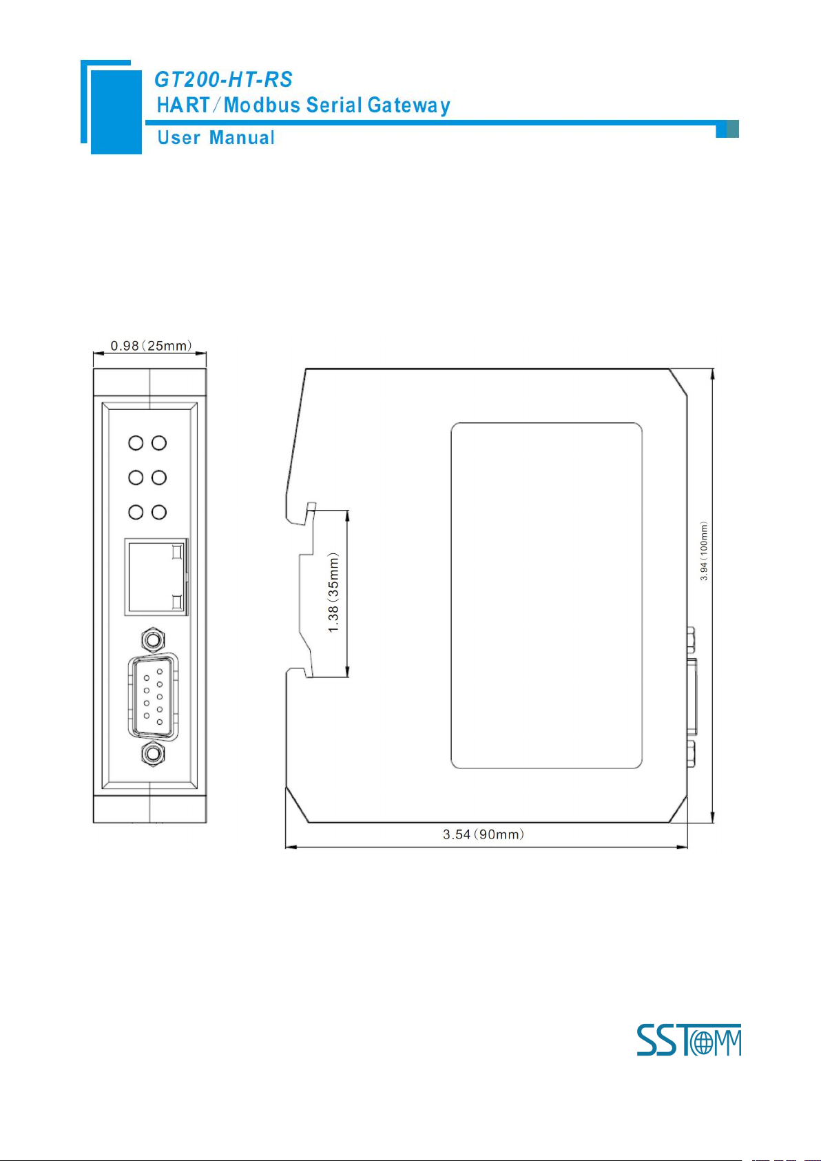
6.1 Machine Dimension
Size: 0.98 in (width)*3.94 in (height)*3.54 in (depth)
6.2 Installation Method
Using 1.38 in (35mm) DIN RAIL
Page 52
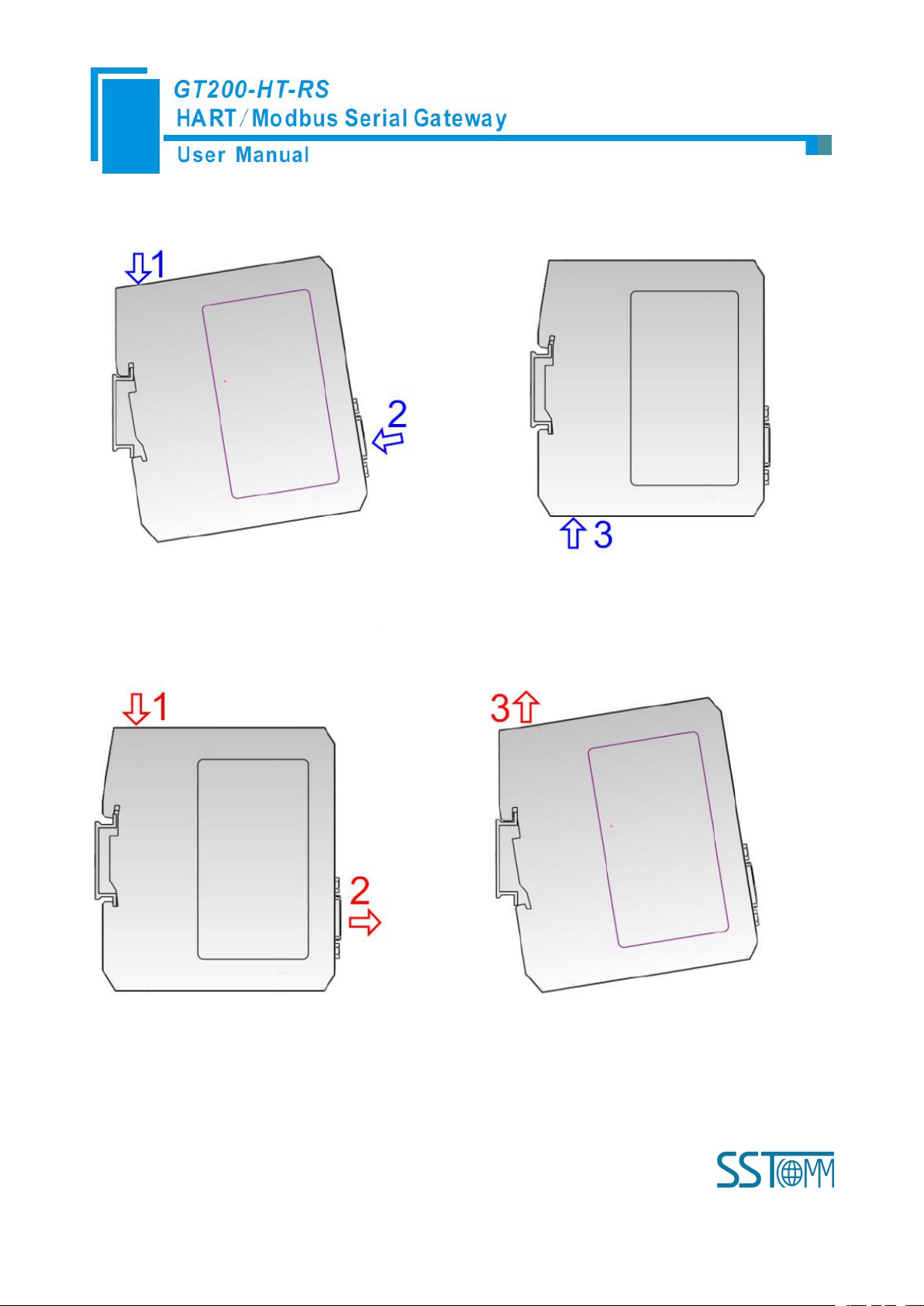
WWW.SSTCOMM.COM 52
Installing the gateway
Uninstalling the gateway
 Loading...