

Page 1

HART/ Modbus TCP Gateway
GT200-HT-MT
User Manual
V 1.2 REV A
SST Automation
E-mail: SUPPORT@SSTCOMM.COM
WWW.SSTCOMM.COM
Page 2

WWW.SSTCOMM.COM 2
Catalog
1 Product Overview...................................................................................................................................................... 4
1.1 Product Function.............................................................................................................................................4
1.2 Product Features............................................................................................................................................. 4
1.3 Technical Specifications................................................................................................................................. 4
1.4 Safety and Explosion-Proof Features............................................................................................................. 5
1.5 Related Products............................................................................................................................................. 5
1.6 Revision History............................................................................................................................................. 5
2 Quick Start Guide...................................................................................................................................................... 6
2.1 Configuration of Gateway.............................................................................................................................. 6
2.1.1 Pre-configured Settings....................................................................................................................... 6
2.1.2 Software Configuration....................................................................................................................... 6
2.2 Function Demo............................................................................................................................................. 10
3 Hardware Descriptions.............................................................................................................................................11
3.1 Product Appearance...................................................................................................................................... 11
3.2 Indicators.......................................................................................................................................................12
3.3 Configuration Switch/Button........................................................................................................................12
3.3.1 Status Setting Switch......................................................................................................................... 12
3.3.2 Internal / External Sampling Resistor Switch................................................................................... 13
3.4 Interface........................................................................................................................................................ 13
3.4.1 Power Interface..................................................................................................................................13
3.4.2 Ethernet Interface...............................................................................................................................14
3.4.4 HART Interface..................................................................................................................................14
3.5 Topology of GT200-HT-MT and Fieldbus Devices..................................................................................... 15
4 Software Instructions............................................................................................................................................... 17
4.1 Software Interface Description.....................................................................................................................17
4.2 Software Functional Specifications..............................................................................................................20
4.2.1 Configure the Fieldbus...................................................................................................................... 20
4.2.2Configure the HART Fieldbus............................................................................................................20
4.2.3 Conflict Detection..............................................................................................................................27
4.2.4 AutoMap............................................................................................................................................ 28
4.2.5 Upload Configuration........................................................................................................................ 29
4.2.6 Download Configuration...................................................................................................................31
4.2.7 Memory Data Display....................................................................................................................... 31
4.2.8 Diagnose............................................................................................................................................ 33
4.2.9 Switching Tools................................................................................................................................. 36
5 Working Principle.................................................................................................................................................... 38
5.1 Flowchart of Executing One HART Command........................................................................................... 42
5.2 Universal Send and Receive Data................................................................................................................ 42
Page 3

WWW.SSTCOMM.COM 3
5.3 Trigger Command.........................................................................................................................................43
5.4 Data Exchange with Modbus TCP............................................................................................................... 44
6 Installation................................................................................................................................................................45
6.1 Machine Dimension......................................................................................................................................45
6.2 Installation Method.......................................................................................................................................45
Page 4

WWW.SSTCOMM.COM 4
1 Product Overview
Simple to use: users can refer to product manuals and application case to achieve communication in a short
Ethernet 10/100M adaptive;
Rich debugging features, the command of the subsection mapping function, the visual display of data
With configuration software, it can configure the HART command and parameters of Modbus TCP Server.
[1] HART interface can be used as a primary master or the secondary master;
[2] Supports one HART channel, supports connecting at most 13 instruments with gateway internal resistor (270
[3] HART interface supports single-point and multi-point mode;
[4] Under single-point mode, supports data burst operation;
[5] Supports all commands of the HART protocol;
[6] Each HART command can be configured for change-of-state output, polling output, initialization output or
[7] Supports up to 100 HART commands, the output data buffer area can be up to 2000 bytes, and the input data
1.1 Product Function
GT200-HT-MT is a gateway that can exchange data between HART and Modbus TCP. HART interface can
be configured as a primary master or a secondary master. Modbus TCP side acts as a slave.
1.2 Product Features
time according to the requirements of the configuration;
exchange, HART slave command diagnostic functions greatly facilitate the user's communication test;
1.3 Technical Specifications
Ω/2W) and supports connecting 15 instruments with an external resistor (250Ω/2W);
no output;
Page 5

WWW.SSTCOMM.COM 5
buffer area up to 3000 bytes;
[8] Each channel can choose to use an internal or external HART sampling resistor;
[9] Supports IP address conflict detection and auto routing ,Modbus TCP slave supports at most 36 connection
[10] Power: 24VDC (9V~30V), <100mA (24VDC)
[11] Working circumstance temperature: -4℉~140℉(-20℃~60℃), Rel Humidity: 5%~ 95% (non-condensing);
[12] External dimensions(W*H*D):1.57 in*4.92 in*4.33 in(40mm*125mm*110mm);
[13] Installation: 1.38 in (35mm) DIN RAIL
[14] Protection Level: IP20
Revision
Date
Chapter
Description
REV A
02/11/2017
ALL
V1.2_Rev A new release,
open the memory data
display, diagnosis, mode
selection and other
functions, increase the
4.2.7, 4.2.8 chapters.
and 512 command request simultaneously;
1.4 Safety and Explosion-Proof Features
GT200-HT-MT is not the product with the features of safety and explosion-proof, please put it in the control
room when using.
1.5 Related Products
The related products include: GT200-3HT-RS and GT200-HT-DP etc.
If you want to get more information about related products, please visit SSTCOMM website:
http://www.sstcomm.com.
1.6 Revision History
Page 6
WWW.SSTCOMM.COM 6
2 Quick Start Guide
1. Turn gateway's "mode" DIP switch to "ON" and "function" DIP switch to "OFF"
2. Use crossed network cable to connect the gateway's Ethernet port (RJ45 interface) with that of computer;
3. Power on the gateway, now the IP address of the gateway is fixed: 192.168.0.10 and it is configurable.
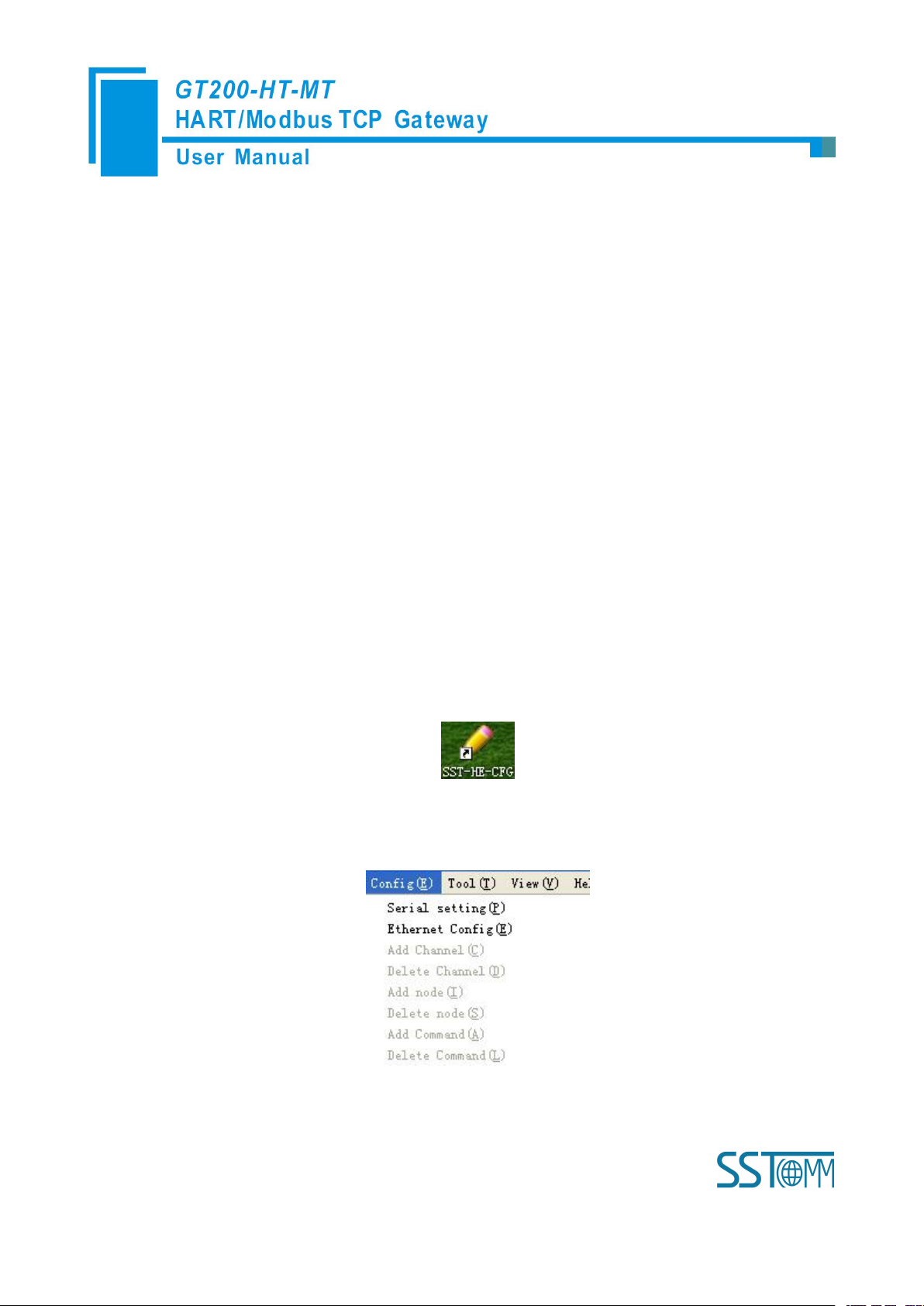
1. Open the SST-HE-CFG software installed on your computer;
2. Click "Fieldbus", in the "Mode" item on the right, choose Modbus TCP;
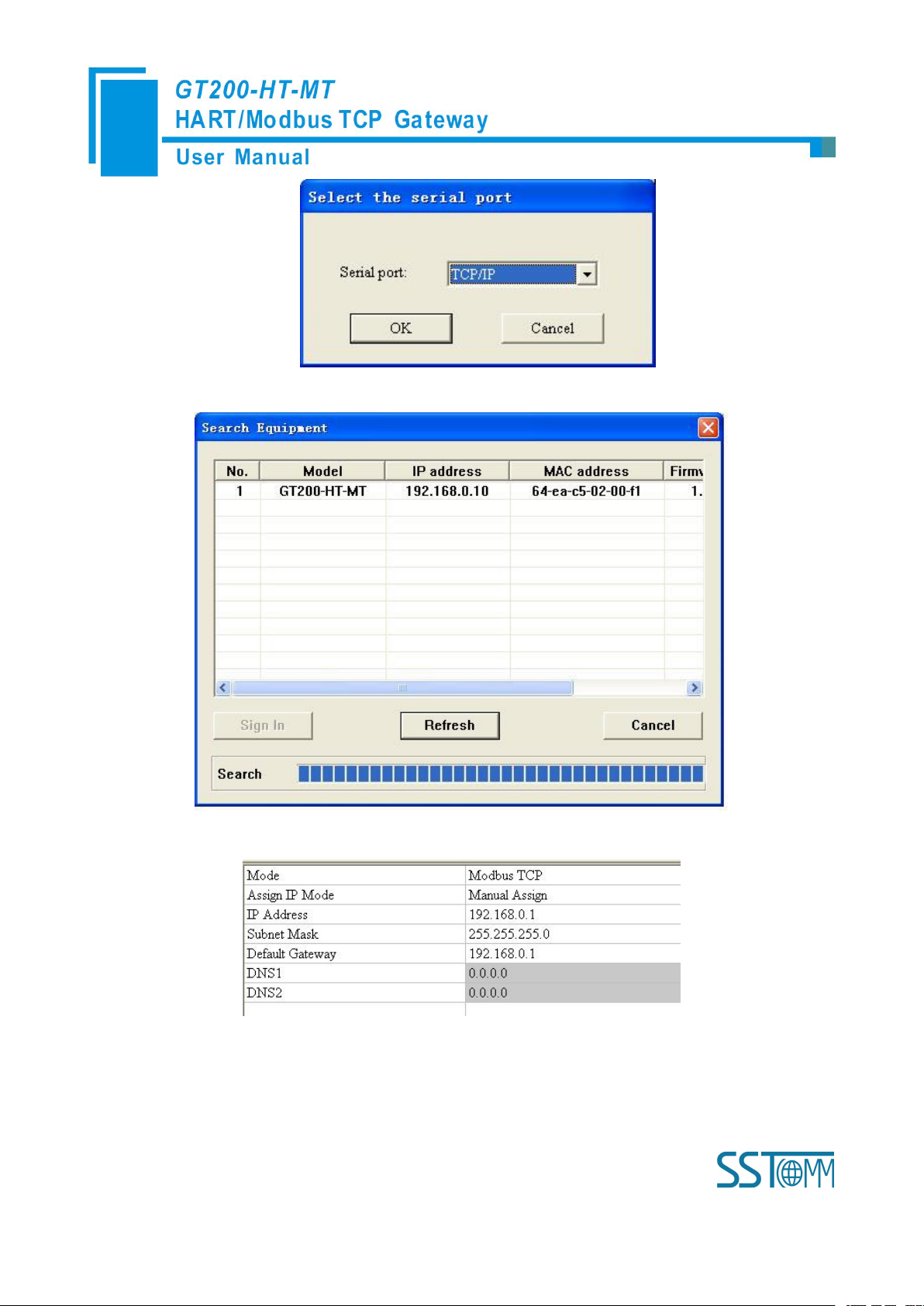
3. Click "Serial setting" in "config" menu, pop up the "Select the serial port" dialog box;
The following example introduces the use of the Gateway.
2.1 Configuration of Gateway
2.1.1 Pre-configured Settings
2.1.2 Software Configuration
Page 7
WWW.SSTCOMM.COM 7
4. Click "OK"; Select the gateway and Sign in the popup "Search Equipment" dialog box;
5. Select the "Fieldbus" in the tree view on the left, configure as below in the right interface;
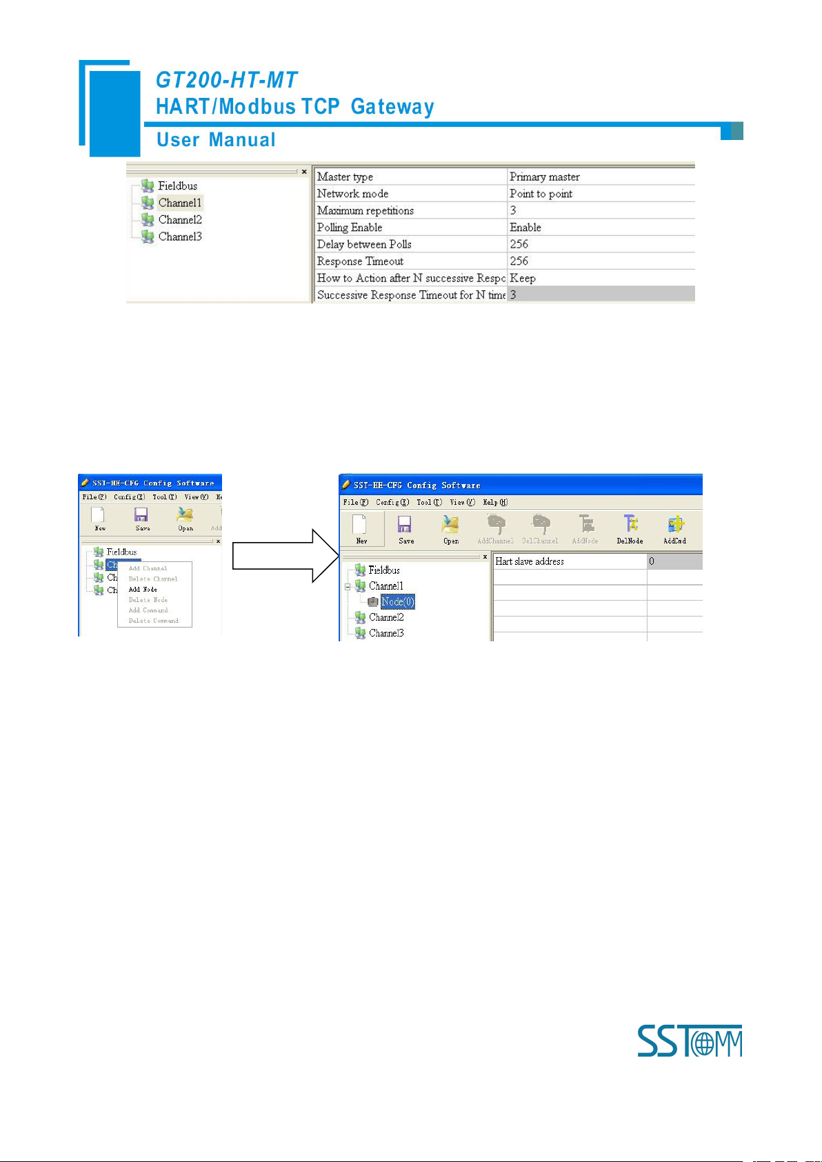
6. Click the channel in the tree view on the left, the table appearing on the right is configured as below:
Page 8
WWW.SSTCOMM.COM 8
Note: In the HART protocol, it specifies that the device with slave address 0 works under single point mode, it
allows digital communication and analog communication exist at the same time. The device with slave address
0~15 works under the multipoint mode, the analog output of the device is the minimum value (4mA) and it only
allows digital communication. The protocol also specifies that the default factory address is No.0.
7. Right click the channel, select "Add Node" in the popup menu as below:
8. Right click: "Node(0)", select "Add Command" in the popup menu, add Command ID1 in the popup dialog
box (double click "Command ID1" or select "Command ID1" and click "»"), click OK to return.
Page 9

WWW.SSTCOMM.COM 9
9. Click "Command ID1", the configuration table on the right is configured as below:
10. Click the icon , in the pop-up dialog box, select the Ethernet port with which gateway is connected to
the computer, and then click Download:
Page 10
WWW.SSTCOMM.COM 10
2.2 Function Demo
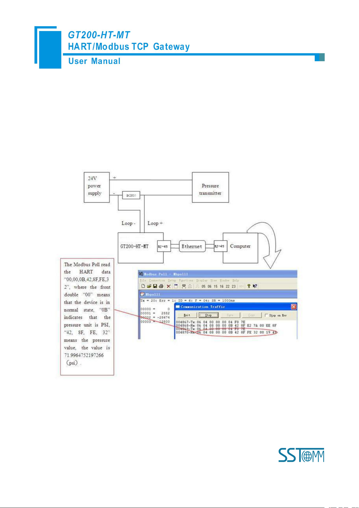
The HART interface of the gateway GT200-HT-MT connects with a 2-wire pressure transmitter with slave
address 0. The Ethernet port is connected to the PC through network cable. The configured Modbus POLL
software in PC can simulate to work as a Modbus TCP master, and then you can see the main variable value of the
pressure transmitter in data exchange window:
Page 11
WWW.SSTCOMM.COM 11
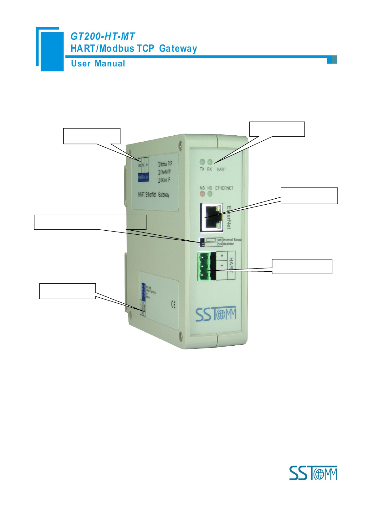
3 Hardware Descriptions
HART Interface
24VDC Interface
DIP Switch
Switch of sampling resistor
Ethernet interface
Status indicators
3.1 Product Appearance
Note: This picture is for reference only. Product appearance should refer to the real object.
Page 12
WWW.SSTCOMM.COM 12
3.2 Indicators
Indicator
State
State description
TX
Blinking
HART channel data is sending
OFF
No data sending
RX
Blinking
HART channel data is receiving
OFF
No data receiving
NS
Green LED OFF
No Modbus TCP data is exchanging
Green LED Blinking
Modbus TCP data is exchanging
MS
Red LED ON
Indicate confliction of IP address
Red LED Blinking
Connection OFF, configuration status, DHCP, BOOTP, IP
address conflict detection with Modbus TCP
Red LED Blinking
(For 3 seconds)
Connection OFF with Modbus TCP
Debugging (bit 1)
Configuration (bit 2)
Description
Off
Off
Run mode, enable read/write the
configuration data
Off
On
Run mode, disable read/write the
configuration data
On
Off
Configuration mode, IP address is
fixed: 192.168.0.10, User can
read/write the configuration data
OnOnReserved
Off
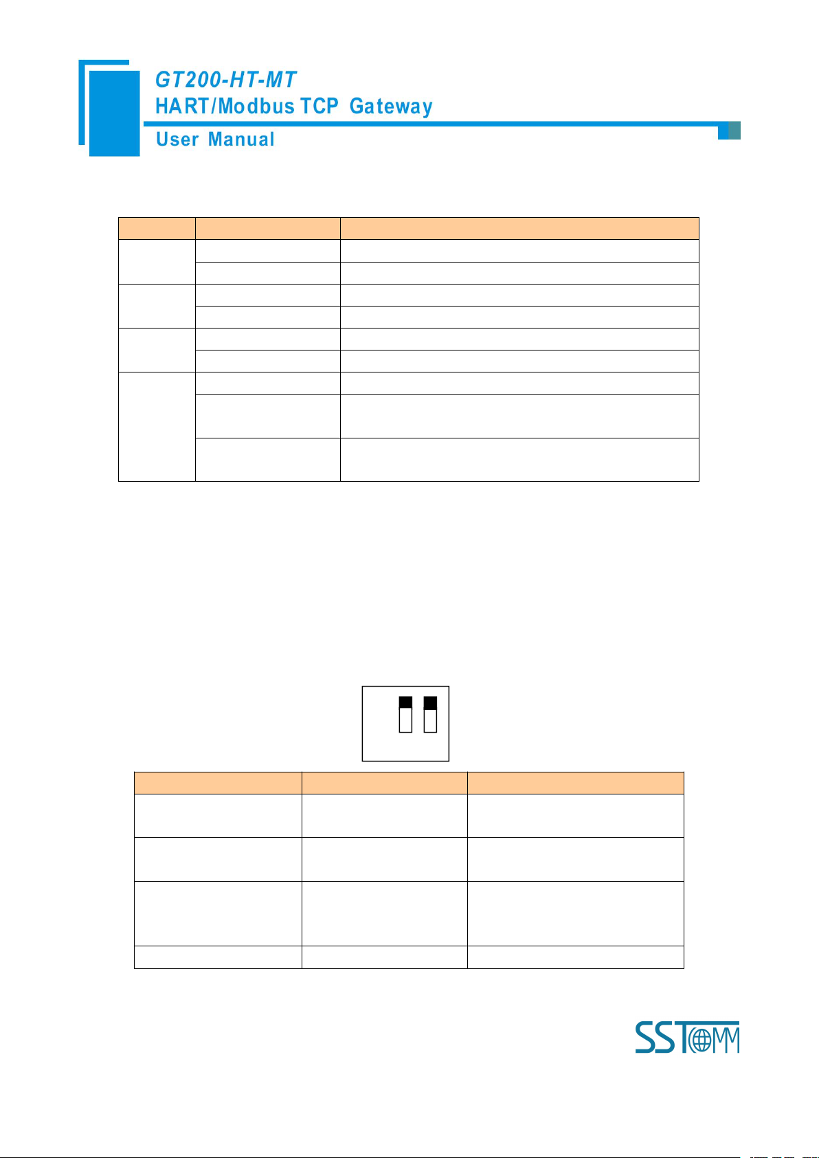
On 1 2
3.3 Configuration Switch/Button
3.3.1 Status Setting Switch
Configuration switch is located at the bottom of product, bit 1 is the mode selecting bit and bit 2 is the
function setting bit.
Note: After re-configuring the switch, you have to restart the GT200-HT-MT to make the settings take effect!
(Power off then Power On)
Page 13
WWW.SSTCOMM.COM 13
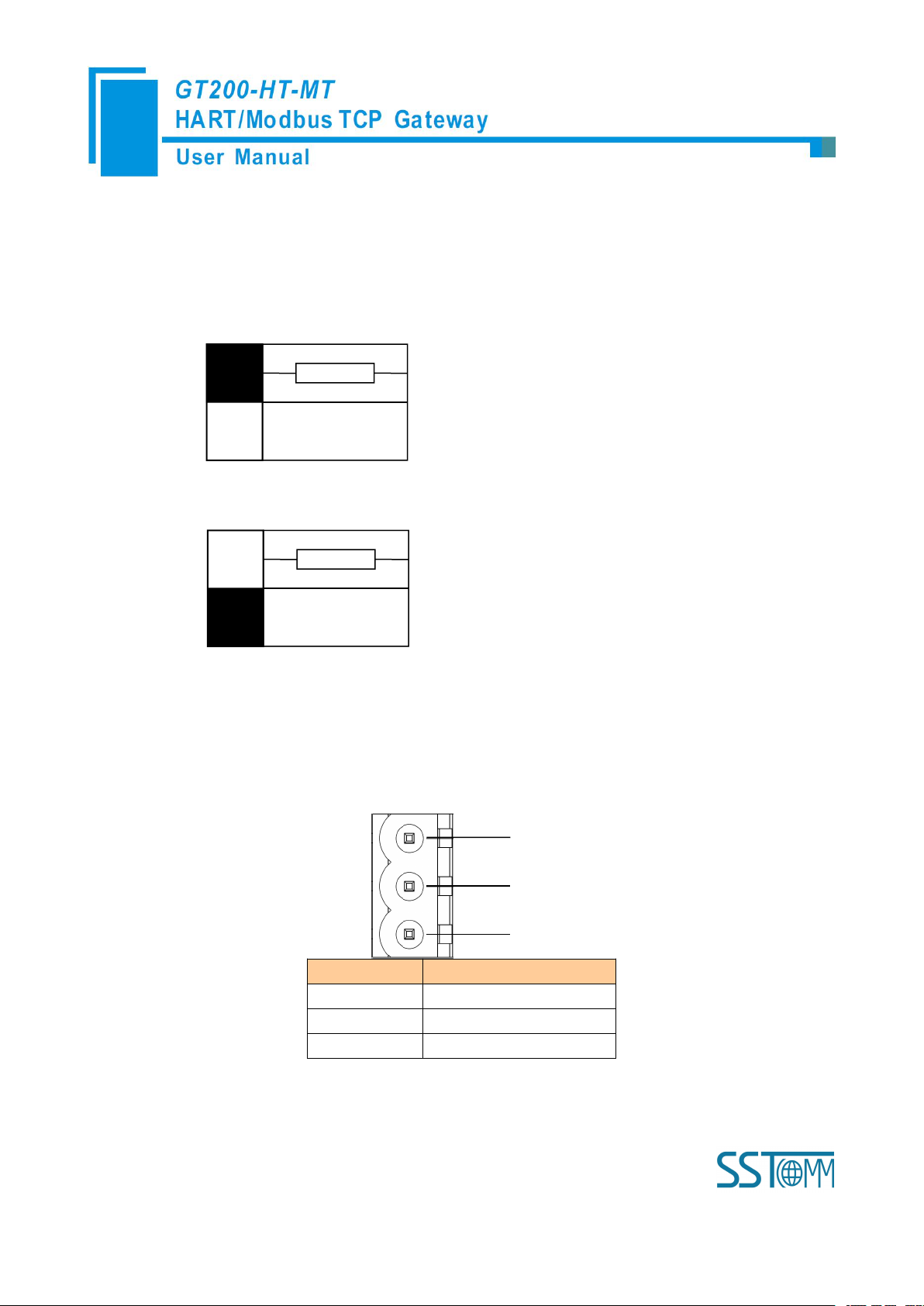
3.3.2 Internal / External Sampling Resistor Switch
Switch to ON, using the internal
sampling resistor
Switch to OFF, using the external
sampling resistor
GND
NC
24V+
1
2
3
Pin
Function
1
Power GND
2
NC(Not Connected)
3
24V+, DC Positive 24V
GT200-HT-MT can choose using the internal sampling resistor or external sampling resistor to get the HART
signal. The specification of the internal resistor is 270Ω, 2W. When the power of the sampling resistor is more
than 2W, you must use an external resistor.
3.4 Interface
3.4.1 Power Interface
Page 14
WWW.SSTCOMM.COM 14
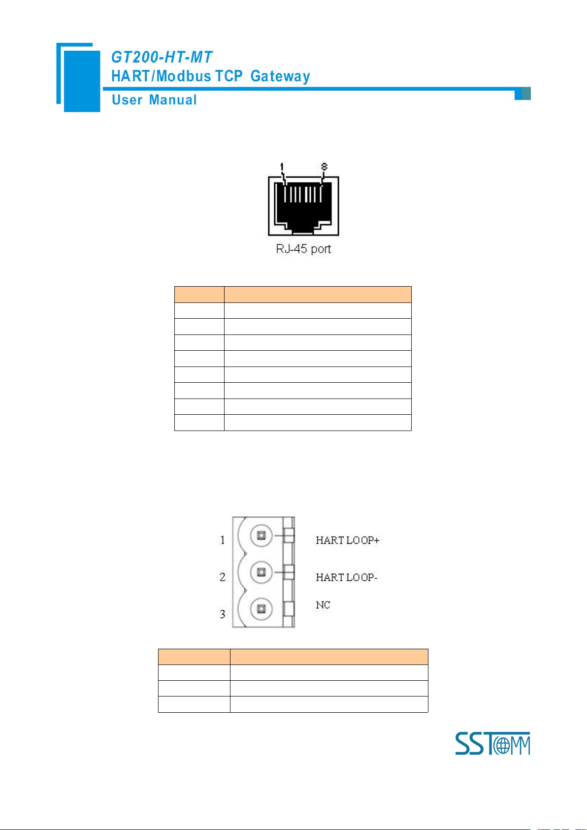
3.4.2 Ethernet Interface
Pin
Signal description
S1
TXD+, Tranceive Data+, Output
S2
TXD-, Tranceive Data-, Output
S3
RXD+, Receive Data+, Input
S4
Bi-directional Data+
S5
Bi-directional Data-
S6
RXD-, Receive Data-, Input
S7
Bi-directional Data+
S8
Bi-directional Data-
Symbol
Function
HARTLOOP+
Connect HART signal negative
HARTLOOP-
Connect 24V power negative
NC
Not connected
Ethernet interface uses RJ-45 plug-in; its pin (standard Ethernet signal) is defined as below:
3.4.4 HART Interface
HART Channel
Page 15

WWW.SSTCOMM.COM 15
3.5 Topology of GT200-HT-MT and Fieldbus Devices
Page 16

WWW.SSTCOMM.COM 16
Note: 1. Some HART slave instrument need to perform self-test and other internal work when power is on, they
may not start HART communication, then gateway cannot receive the response data of the instrument right now. It
is recommended the HART slave instrument and gateway uses separate power supply so that the gateway can
immediately establish communication with instrument.
2. When configuring HART commands in the software SST-HE-CFG, the commands need to be
configured according to the actual demands. To improve the speed of bus communication, it is recommended not
to configure the empty node (in fact, not connected to the node) and empty commands (the actual unnecessary
commands).
Page 17

WWW.SSTCOMM.COM 17
4 Software Instructions
Equipment section: can
choose the operating
targets, including field
bus or subnet, add the
nodes and commands
Menu Bar
Tool Bar
Title Bar
Configuration section:
Input configuration
parameters, gray part is
not modifiable, white
part is modifiable
Notes section: The
specific explanation of
the nouns appearing in
the configuration and
devices to help users
understand
4.1 Software Interface Description
SST-HE-CFG is configuring software based on Windows platform and it is used to configure HART series
products of gateway.
The following describes how to use the software SST-HE-CFG to configure the product GT200-HT-MT.
Double-click on the icon to enter the main interface of software:
Tool Bar:
Toolbar interface shown as follow:
Page 18

WWW.SSTCOMM.COM 18
The function from left to right is: New, Save, Open, AddChannel, DelChannel, AddNode, DelNode, AddCmd,
DelCmd, Upload, Download, AutoMap, Conflict, Export, Memory, Diagnose, Debug and Mode Switch.
GT200-HT-MT doesn't support function of "Memory", "Diagnose", "Debug" and "Mode switch"
temporarily.
New:
Create a new configuration file
Save:
Save the configuration file
Open:
Open the configuration file
AddChannel: This function can't be used temporarily
DelChannel: This function can't be used temporarily
AddNode: Add a HART slave node
DelNode: Delete a HART slave node
AddCmd: Add a HART command
DelCmd: Delete a HART command
Page 19
WWW.SSTCOMM.COM 19
command
data buffer
Upload: Read the configuration information from the module and shown in the software
Download: Download the configuration file to the gateway
AutoMap: Used to automatically calculate the mapped memory address without confliction by each
Conflict: To check whether there are some conflicts with configured commands in the gateway memory
Export: Output current configuration to the local hard disk and saved as Excel spreadsheet form
Memory: Show the data exchange situation inside of the gateway. GT200-HT-MT doesn't support this
function temporarily.
Diagnose: through this function could analyze operating condition of fieldbus device; also it can finish
some certain analysis. GT200-HT-MT doesn't support this function temporarily.
Debug: through this function could send any request frame to Hart fieldbus and show the response
information received in HART, convenient to debug. GT200-HT-MT doesn't support this function temporarily.
Mode Switch: Specify that the operation of the gateway is debugging or configuring. GT200-HT-MT
Page 20

WWW.SSTCOMM.COM 20
doesn't support this function temporarily.
4.2 Software Functional Specifications
4.2.1 Configure the Fieldbus
Click the "Fieldbus" in the tree view on the left, select "Modbus TCP" in the "Mode select" in the
configuring plate on the right and then click enter to confirm. It is shown below:
Here user can configure some parameters:
IP setting mode: Static configuration, BOOTP, DHCP optional;
IP address: Set the IP address of GT200-HT-MT;
Subnet mask: Set the subnet mask of device;
Gateway address: Set the gateway address of device;
DNS1: Default 0;
DNS2: Default 0;
4.2.2Configure the HART Fieldbus
4.2.2.1 Set the Parameters of HART Channel
Click the "HartChannel0" in the tree view, the configuration plate will be shown in the right place:
Page 21

WWW.SSTCOMM.COM 21
Master type: Primary master, Secondary master
Network mode: Select the networks link as single or multiple points, under the single point the gateway can only
communicate with the slave device whose address is 0;
Maximum repetitions: Select times of command resending, range: 0~5
Enable Polling: Whether to use polling function, "Enable" means using polling function.
Polling time: Set the polling time (Time interval between one command sending and beginning to send next
command), the range is 256~65535ms
Response timeout: Set the maximum time of waiting response from slave, the range is 256~65535ms
Input data timeout clear/keep: After HART command exceeds the setting no-response times, whether to clear input
data buffer area of HART
Timeout times: Set the timeout times
4.2.2.2 Add Slave Nodes
Click the selected HART channel, right click the mouse and select "Add Node" in the popup menu.
Page 22

WWW.SSTCOMM.COM 22
Click the added node, set slave address in the right configuration plate, and please notice that HART channel can
only be equipped with one slave node whose address is 0.
Note: When configured node numbers are more than the actual connected devices, the redundant node will lead to
the longer time of polling circle; so, it is recommended that configured node numbers should corresponds with actual
devices.
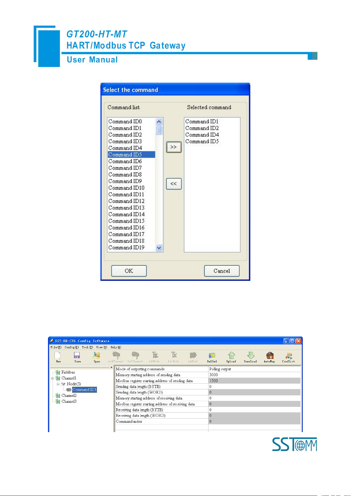
4.2.2.3 Add Commands
Click the selected "Node ()", right click the mouse and select "Add Command" in the popup menu
Page 23
WWW.SSTCOMM.COM 23
Choose the command you want to add in the popup dialog box, and then click "OK" to exit:
Note: the same command can only be configured once in one node.
4.2.2.4 Configure Slave Commands
Click the command ID in the tree view; you will see the configuration plate of command in the right place:
Page 24

WWW.SSTCOMM.COM 24
Mode of outputting command: You can use the execution way of the command, change-of-state, polling output,
Change-of-state output: Execute this command once s data buffer of HART changes
Polling output: This order is put in the polling list, executed periodically
Initialization output: Execute the command only once when power is on
Disable output: the command will not be sent.
Initialization output and disable output optional;
Memory starting address of sending data: Set the memory starting address of output data by this command, the
range is 3000~4999;
The register starting address of sending data: the property is automatically calculated by gateway, used for register
addressing;
Sending data length (byte): used to set the length of output data by this command;
Sending data length (word): the property is automatically calculated by gateway, used for user checking output
data length, 1 word=2 byte;
Memory starting address of receiving data: set the memory address of input data by this command. Response data
only includes data area of HART frame;
The register starting address of receiving data: the property is automatically calculated by gateway, used for
register addressing;
Receiving data length (byte): set the length of input data by this command;
Receiving data length (word): the property is automatically calculated by gateway, used for user checking output
data length conveniently, 1 word=2 byte;
Command index: the property is automatically calculated by the configuration software, it indicates the index in
the configured command list this command belongs to.
4.2.2.5 Delete Commands
Select the command need to be deleted, Right click the mouse and click "Delete Command". Through the menu
command can also be the same action.
Page 25

WWW.SSTCOMM.COM 25
4.2.2.6 Delete Nodes
Select the node needed to be deleted, Right click the mouse and click "Delete Node". Through the menu
command can also be the same action.
4.2.2.7 Advanced Options to Configure Slave Commands
When using HART command configuration, sometimes users want to get one part data of one command. For
example, No.1 HART command. The float value of main variable is only needed, no need to get unit of main
variable, this is why advanced option exists. Advanced options is actually the execution of "segment mapping
function", it cut the response data of HART command and get the segment data. Users can get any part data they
want. Below is the interface of Advanced Options:
This interface details is described in chapter 4.2.2.4, so here we don't describe it. The below is the example of
No.3 HART command, to show how to use "Segment Mapping" function, we can see one "configuration"
button after the "receive data project configuration" option, click it:
Page 26

WWW.SSTCOMM.COM 26
There are many parts in "Bytes". For example, "Command Status" means the communication status and
relevant code of HART response command, "Byte0-3" means byte 0 to 3 of data area of HART response
command, and so on.
In the above example, click "Byte5-8" will show the Primary Variable in the left bottom area. Other
columns have the relevant explanation.
First to explain the "Mapped Address":
Bytes: response bytes of "Response Data";
Memory Address: assigned memory address which this byte is located in memory buffer area of
GT200-HT-MT;
Modbus register address: the relevant Modbus register address of "Memory Address"; Note: this address is
not a single address, which is the same memory area which it occupied.
Byte swap: there are two options, "no swap" and "register swap", swap option is only valid to float type
data. When using "no swap", the byte order is byte1, byte2, byte3 and byte4. After using "register swap", the
byte order will be byte3, byte4, byte1 and byte2. For example, the original data is 0x12345678, it will be
0x56781234 after using "register swap".
Page 27

WWW.SSTCOMM.COM 27
Choose "Byte0-3" and "Byte5-8", click auto mapping, as shown below:
Close the dialog box, download the configuration into GT200-HT-MT.
Others are the same with "Basic Mode".
4.2.3 Conflict Detection
Conflict detection is used to check the distribution condition of the input and output data of all commands stored in
the memory.
Click icon will show the conflict detection interface as follow:
Page 28

WWW.SSTCOMM.COM 28
The left side is configuration commands, the right side is data memory address including receive data storage
address and send data storage. Upper side is memory distribution of the HART's sending data; lower side is memory
distribution of the HART's receiving data. When one memory unit is configured with two commands or more, the
memory unit will display red color. When the distributed memory exceeds the defined scale of gateway, the exceeding
part will display yellow color. White color area shows the usable memory. Green color area indicates occupied memory.
Clicking one command, the distribution chart shown in blue will show the storage location of input/output data.
4.2.4 AutoMap
Automap will automatically distribute the memory with no confliction according to the input/output bytes
number by users' commands.
You should set the correct input/output bytes for each commands, then click label, select "yes" in the
Page 29

WWW.SSTCOMM.COM 29
popup menu.
Select the configuration interface:
Show the "Ethernet Config" interface as below:
4.2.5 Upload Configuration
When checking "Use the search function", it will search all identifiable hardware when the software is
communicating with the hardware and will be shown in the device list:
Page 30

WWW.SSTCOMM.COM 30
Select the device, click "Sign in" to connect the device.
When not checking "Use the search function", it will only search appointed hardware and only show this
Click the upload icon again, pop up the dialog box below:
Click "Upload data" button.
hardware in the device list.
Page 31

WWW.SSTCOMM.COM 31
Now, user can upload the configuration of GT200-HT-MT into the software and shown in the software.
1. Ensure that the GT200-HT-MT's function bit of DIP switch is in the ON state and the mode bit of
2. Use a network line to connect the GT200-HT-MT's RJ-45 port and computer. Open the software
4.2.6 Download Configuration
After configuring the command, click button, pop up the dialog box below:
Click download data.
Note: Before downloading, please confirm all configuration data are correct.
4.2.7 Memory Data Display
Show the data exchange inside of the gateway, users can use this function to debug the HART fieldbus in the
absence of the EtherNet/IP side. Steps are as follows:
DIP switch is in the OFF state, restart the gateway. GT200-HT-MT is in the run mode.
Page 32

WWW.SSTCOMM.COM 32
"SST-HE-CFG", Click "Tool—Select Mode" and choose debug mode and then click on the
icon , you can also click to choose debug mode. Choose the correct gateway in the
device scanning window, interface is as follows:
As is shown in the table, upper table shows the memory distribution of HART input data, lower table shows
the output data. When you need to change the output data, click the "stop" button firstly, then change the related
data or load the already saved data table, at last, click the "sending data".
Page 33

WWW.SSTCOMM.COM 33
4.2.8 Diagnose
The device diagnostics function allows the user to know which devices are not communicating properly, the
execution of commands assigned, the status of the gateway's data transmission and reception, the display of
specific commands, and the real-time display of HART device data. The steps are as follows:
1) First, dial the DIP switch of GT200-HT-MT to "1OFF2OFF", then power on again. At this moment
GT200-HT-MT is in running mode.
2) Connect the network port of GT200-HT-MT to the computer, open the HTConfig software, click debug
mode pop up the dialog box "Tools -> Select Mode", then select the diagnose in the tool or click the icon
, select the debug mode, click OK, and then click software pop up a dialog box to
upload the gateway configuration, as shown below:
Page 34

WWW.SSTCOMM.COM 34
3) Click "Upload Data" to pop up the following picture:
4) Click "OK" to enter the diagnostic interface:
Page 35

WWW.SSTCOMM.COM 35
Click "Channel 1" in this interface, the right side of the gateway will display the status of the HART bus
section, click "Update" will refresh the data once, click "Reset" will clear the system status, click " periodically
refresh", the software will update the data in 500ms.
5) Click Node (x) appears below:
This screen shows the response status of the configured command.
Click "Update" will refresh these command status, "Cycle Update" will update the command status
500ms
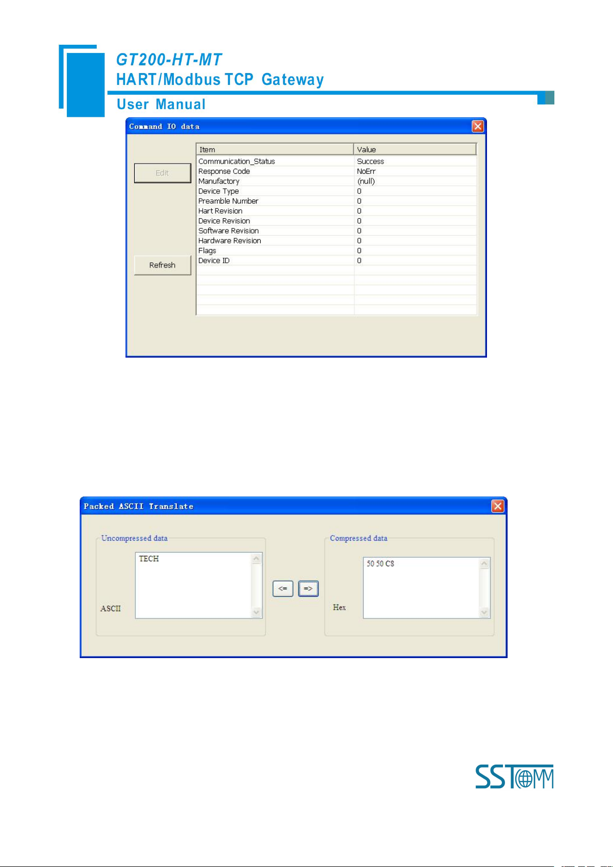
6) Double-click 0, 1, 2, 3, 6, 11, 12, 13, 14, 15, 16, 17, 18, 19 commands will pop up their command
information, input 6, 17, 18, 19 commands.
Double click "CMD0" to pop up the following window:
Page 36
WWW.SSTCOMM.COM 36
Click "Update" to update the data, "Edit" in the read-only command does not work.
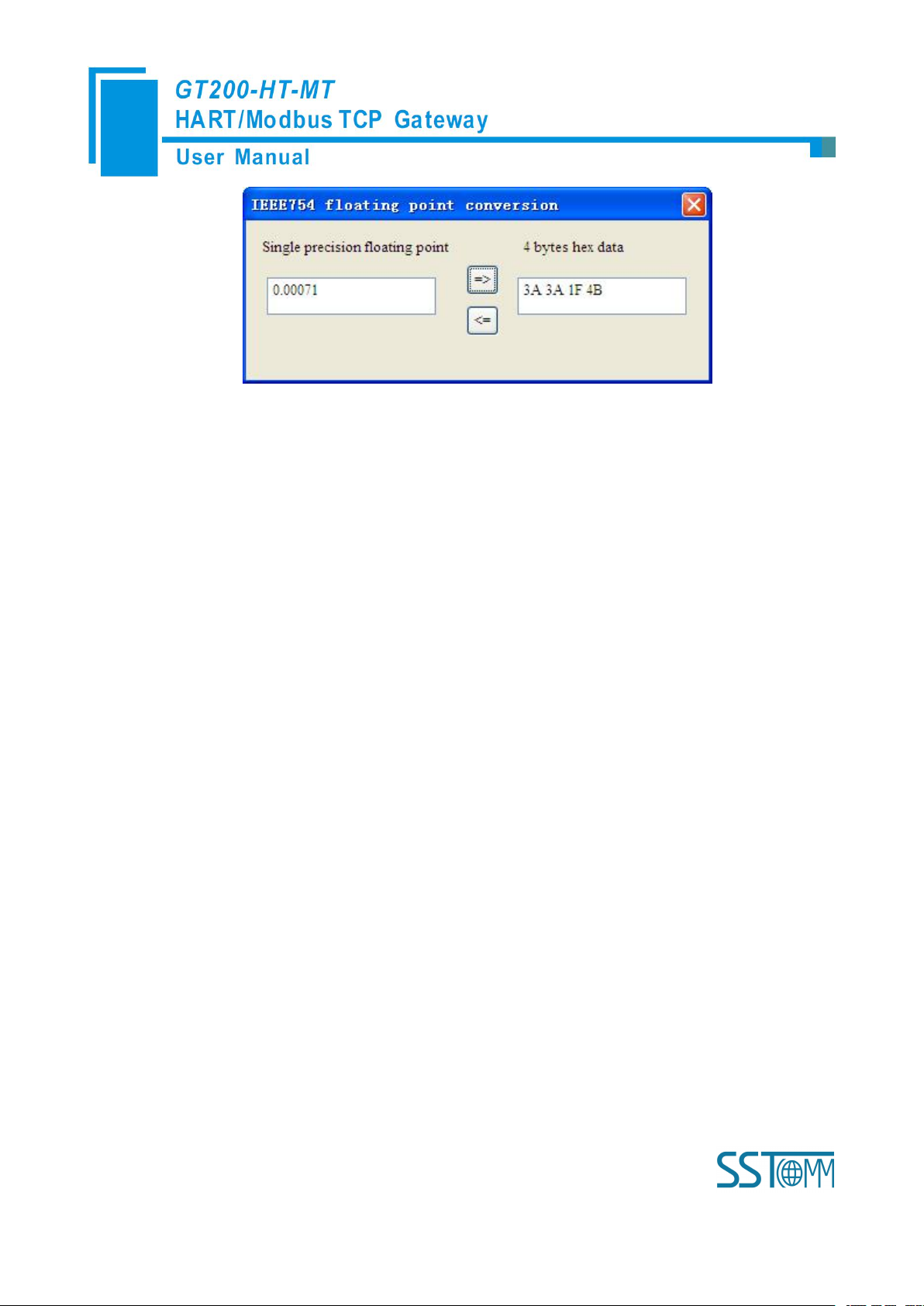
4.2.9 Switching Tools
In the "Tools" menu, there are two practical tools: They are used to switch between IEEE754 and PACKED
ASCII conveniently.
Page 37
WWW.SSTCOMM.COM 37
Page 38
WWW.SSTCOMM.COM 38
5 Working Principle
Gateway
memory
address
Corresponding
Modbus register
address
Data shift
offset in
channel
Read/write
permission
Description
Three
HART
channel
sharing
memory
0-2999
0-1499
read
The HART data input
area
3000-499
9
1500-2499
read, write
The HART data
output area
HART
channel
5000-501
9
800-809
0-19
read
Device 0_cmd0 data
5020-503
9
810-819
20-39
Device 1_cmd0 data
……
……
……Device 15_cmd0
data
5320
960H
320
Gateway status
5321
960L
321
Gateway HART port
sending times
5322
961H
322
Gateway HART port
receive times
5323
961L
323
HART
communication error
times
1924-194
3
962-971
Reserved
5324
972H
324
The response status
Device 0_cmd0
5325
972L
325
The response status of
device 1_cmd0
……
……
……The response
The gateway internally opens up a length of 8156 bytes of memory as input and output buffers which
exchange data. 0 ~ 4999 memory is used as the storage area of the HART input data and output data. 5000~8155
memory is used as the storage area of the status of three HART channel and control variables. The specific
assignment is shown in the table below:
Page 39

WWW.SSTCOMM.COM 39
status of Device15
_cmd0
5340-543
9
980-1059
340-439
The response status of
user command
5440
1060-1195
Reserved
5440
1196H
440
Universal receive
label
5441
1196L
441
Universal receive
error counter
5442-54431197
442-443
Universal receive data
length
5444-574
3
1198-1347
444-743
Universal receive data
2696-2999Reserved
3000-399
9
0000-0499
HART data output
area
5744
0500H
744
Read/Write
Reset to send, receive,
error counter
5745
0500L
745
Polling enabled
5746
0501H
746
Trigger label
5747
0501L
747
Trigger command
4004-426
9
0502-0634
Reserved
5748
0635H
748
Universal send label
5749
0635L
749
Universal mode
enabled
5750-57510636
750-751
Universal send data
length
5752-605
1
0637-0786
752-1051
Universal send data
The HART data input area: Store the data that HART slave device sends to gateway. All command response
data of HART channel will be mapped here.
The HART data output area: Store the data that the gateway sends to the HART slave device. All HART
Device 0_cmd0~ Device 15_cmd0: When operating one slave command for the first time, the gateway
command will get the output data here.
Page 40

WWW.SSTCOMM.COM 40
internally will automatically execute the No. 0 command to obtain the device information (to obtain the long
Gateway status: The gateway status indicates the state of the gateway in the HART network, defined as:
Send times of HART channel: HART Transmit counter
Receive times of HART channel: HART Receive counter
Communication error times of HART channel: HART Receive Error counter
Device 0_cmd0~ Device 15_cmd0's response status: Show the response status of the internal command
The response status of the user command: Show the response status of the user commands
Universal Receive label: The receive label under the universal model, this value changing one time indicates
Universal Receive data length: Indicates the received data length under the universal mode
Universal Receive Error Counter: Indicates the universal received error times
Universal receive data: Store the received data of HART port under the universal mode
Reset to send, receive, error counter: The gateway control signal, when the value of memory changes,
Polling enabled: This bit is readable and writable, writing 1 enables the polling output, writing 0 disables
address). The response data of this internal command is stored in this area.
0---- There are not HART communications.
1----Sending
2---- Waiting for a response
3---- Handing a response
Command state is defined:
0---- Not executed
1---- The correct response
2---- Parity error
3---- No Answer
4---- Error defined in agreement
5----No connecting
that HART port receives a HART frame
gateway causes all the counter to 0
polling output; Reading 1 indicates that the polling state is enabled, 0 indicates that the polling is in the
disabled state
Page 41

WWW.SSTCOMM.COM 41
Trigger label: Changing the value will result in a trigger operation
Trigger command number: Command number executed by trigger operation
Universal mode enabled: The value 1 indicates a universal transfer function is enabled, otherwise disables
universal transfer function
Universal send label: The send label under the universal model, this value changes in time will lead to send a
Universal send data length: The length of send data under the universal mode
Universal send data: the data need to send under the universal mode
Register address calculation formula: Memory address=the original memory address of HART channel+the
HART frame
offset of register; Modbus register address=Memory address/2 (integral part of the result indicates register
address, the remainder indicates the low bit of register address, and otherwise it is the high bit). For example,
the memory address of No.2 HART channel status is: 6052+320=6372. Relevant Modbus register address is:
6372/2=3186H
Page 42

WWW.SSTCOMM.COM 42
5.1 Flowchart of Executing One HART Command
Initialization
output
Satisfy the
polling output
Satisfy Change
of state output
Meet the
trigger output
Execute
command
Input Data
Output Data
Field
instruments
Data
State
Data
Slave's
response
Y
The next
command
Current command
N
N
N
N
Sent to the slave
command frame
Quit
5.2 Universal Send and Receive Data
User can visit/read universal receive/send control variable in order to start the "transparent transmission"
with one HART channel. The detailed steps are as below:
Page 43

WWW.SSTCOMM.COM 43
06H command "common
mode enable" bit is 1
10H command will write the data
to a continuous region which
address begins from "Universal
mode send data"
The length of the data written to
"The universal send data length"
address with 06H command
06H command to change "the
Universal send data label"
The gateway will store the received HART frame in a continuous region within "the Universal receive data"
as a starting address and write the length of the received data to the "Universal receive data length", then change
the value of "universal receive label". If no data is received within the response waiting time, the gateway will
order "universal receive error counter" to plus 1. Before sending the universal frame, all users should read the
universal receive label and the error counter. After finishing the universal frame, it needs to read these two values
continuously until one of them changes.
5.3 Trigger Command
Users can trigger any HART command which is configured by gateway through Modbus TCP. The specific
approach is: appointing Modbus register address to "trigger command ID" of one channel; using command ID6
of Modbus to write the user trigger command number (when using SST-HE-CFG to configure commands, the
software will automatically calculate and display) to the "trigger command number". Then rewriting "the trigger
label" can trigger the value to change and trigger the gateway to finish a trigger operation. Parts of response data
in the device will be stored to "the receive data memory" which is specified by this command number.
Page 44

WWW.SSTCOMM.COM 44
5.4 Data Exchange with Modbus TCP
When fieldbus is configured as "Modbus TCP", user can exchange data, inquire about the status of gateway
and manage according to the corresponding address of gateway in the internal input and output buffer; Also you
can do some trigger operation and transmission of universal frame.
Page 45

WWW.SSTCOMM.COM 45
6 Installation
6.1 Machine Dimension
Size: 1.57 in (width)*4.92 in (height)*4.33 in (depth)
6.2 Installation Method
Using 1.38 in (35mm) DIN RAIL
Page 46

WWW.SSTCOMM.COM 46
Installing the gateway
Unloading the gateway
 Loading...