

Page 1
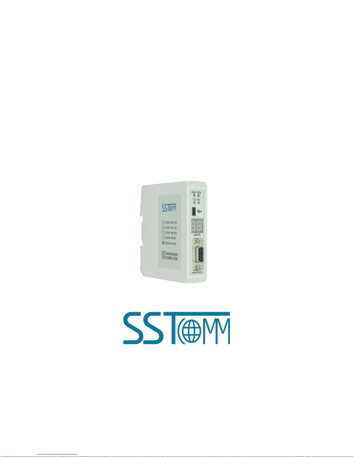
Universal Serial/PROFIBUS DP Gateway
GT200-DP-RS
User Manual
V6.1
SST Automation
E-mail: SUPPORT@SSTCOMM.COM
WWW.SSTCOMM.COM
Page 2

User Manual
Universal Serial/PROFIBUS DP Gateway
GT 200 -D P-R S
WWW.SSTCOMM.COM
2
Catalog
1 About the Gateway
.....................................................................................................................................................................
4
1.1 Product Function
.............................................................................................................................................................
4
1.2 Product Features
.............................................................................................................................................................
4
1.3 Technical Specifications
.................................................................................................................................................
4
1.4 Related Products
.............................................................................................................................................................
6
2 Quick Start Guide
......................................................................................................................................................................
7
2.1 Power Wiring
..................................................................................................................................................................
7
2.2 Wiring with PC
...............................................................................................................................................................
7
2.3 Configuration Method
....................................................................................................................................................
7
2.4 Wiring with Serial Device
..............................................................................................................................................
9
2.5 Wiring PROFIBUS DP Interface
..................................................................................................................................
10
2.6 Debug
............................................................................................................................................................................
11
3 Hardware Descriptions
............................................................................................................................................................
12
3.1 Product Appearance
......................................................................................................................................................
12
3.2 Indicators
......................................................................................................................................................................
13
3.3 LED Display and Button
..............................................................................................................................................
13
3.3.1 LED Display
......................................................................................................................................................
13
3.3.2 PROFIBUS DP Address Setting Button
............................................................................................................
14
3.4 Interface
........................................................................................................................................................................
15
3.4.1 Power Interface
..................................................................................................................................................
15
3.4.2 PROFIBUS DP Interface
...................................................................................................................................
15
3.4.3 RS-485/RS-422 Interface
..................................................................................................................................
16
3.4.4 RS-232 Interface
................................................................................................................................................
17
4 Working Principle
....................................................................................................................................................................
18
4.1 Modbus Master
.............................................................................................................................................................
18
4.2 Modbus Slave
...............................................................................................................................................................
18
5 Universal Mode
........................................................................................................................................................................
20
5.1 Data Exchange
..............................................................................................................................................................
20
5.2 Universal Protocol
........................................................................................................................................................
21
6 Software Instructions
...............................................................................................................................................................
23
6.1 Notes before Configuring
.............................................................................................................................................
23
6.2 User Interface
................................................................................................................................................................
23
6.3 The Operation of Equipment View
...............................................................................................................................
26
6.3.1 Equipment View Interface
.................................................................................................................................
26
6.3.2 Operation Mode of Equipment View
................................................................................................................
26
6.3.3 Operation Types of Equipment View
................................................................................................................
27
6.4 The Operation of Configuration View
..........................................................................................................................
28
6.4.1 Interface of Fieldbus Configuration View
.........................................................................................................
28
6.4.2 Interface of Subnet Configuration View
...........................................................................................................
29
Page 3

User Manual
Universal Serial/PROFIBUS DP Gateway
GT 200 -D P-R S
WWW.SSTCOMM.COM
3
6.4.3 Interface of Node Configuration View
..............................................................................................................
34
6.4.4 Interface of Command Configuration View
......................................................................................................
35
6.4.5 Notes View
.........................................................................................................................................................
37
6.5 Conflict Detection
.........................................................................................................................................................
38
6.5.1 Operation of Command List
..............................................................................................................................
39
6.5.2 Operation of Memory Mapping Area
................................................................................................................
40
6.6 Hardware Communication
............................................................................................................................................
41
6.6.1 Serial Configuration
..........................................................................................................................................
41
6.6.2 Upload Configuration
........................................................................................................................................
42
6.6.3 Download Configuration
...................................................................................................................................
42
6.7 Load and Save Configuration
.......................................................................................................................................
43
6.7.1 Load Configuration Project
...............................................................................................................................
43
6.7.2 Save Configuration Project
...............................................................................................................................
43
6.8 Export EXCEL
..............................................................................................................................................................
44
6.9 Debug
............................................................................................................................................................................
45
6.9.1 Debug Interface of 4.X or 3.X
...........................................................................................................................
46
6.9.2 Debug Interface of 5.x and above
.....................................................................................................................
49
7 PROFIBUS DP Hardware Configuration Instructions
............................................................................................................
54
7.1 Register GSD file
..........................................................................................................................................................
54
7.2 DPRS2A.GSD-Configuration software configuration mode use
..............................................................................
56
7.3 DPRS2M.GSD-DP Hardware Configuration of Modbus master
..............................................................................
57
7.4 DPRS2S.GSD-DP Hardware Configuration of Modbus slave
..................................................................................
62
7.5 DPRS2T.GSD-DP Hardware Configuration of User Config
....................................................................................
65
8 Installation
...............................................................................................................................................................................
69
8.1 Machine Dimension
......................................................................................................................................................
69
8.2 Installation Method
.......................................................................................................................................................
69
Appendix A: Using STEP 7 to Set PROFIBUS DP
...................................................................................................................
71
Appendix B: How STEP7 Access Data of Gateway and Select Data Module
..........................................................................
78
How STEP7 Access Data of Gateway
................................................................................................................................
78
How STEP7 Select Data Module
.......................................................................................................................................
79
Page 4

User Manual
Universal Serial/PROFIBUS DP Gateway
GT 200 -D P-R S
WWW.SSTCOMM.COM
4
1 About the Gateway
1.1 Product Function
The gateway GT200-DP-RS enables data to establish communication between the serial port and PROFIBUS DP
(PROFIBUS DP master such as Siemens PLC). At the same time it can remotely obtain real-time I / O data, status and other
information of the connected PLC and serial device via docking cloud platforms such as bokaiyun to achieve remote
monitoring. The gateway can connect multiple devices with Modbus/RS-485/RS-232/RS-422 interface with PROFIBUS DP,
meaning that Modbus/RS-485/RS-232/RS-422 network devices can be converted to PROFIBUS DP network devices.
1.2 Product Features
Wide Application: Any devices with RS-485/RS-232/RS-422 can be connected to PROFIBUS DP network through
GT200-DP-RS. For example Variable-frequency Drive with Modbus protocol interface, Motor starting protector,
transmitters.
Easy to use: Users don’t need to know more knowledge about PROFIBUS and Modbus, and they can configure the
gateway according to the user manual in a short time without complex programming.
Transparent communication: Users can refer to mapping relations between PROFIBUS DP data area and Modbus data
area to realize the transparent data communication between PROFIBUS DP and Modbus.
1.3 Technical Specifications
1. Act as a PROFIBUS DP slave at the side of PROFIBUS DP, while Modbus master, Modbus slave and Universal
mode can be selected at serial side and serial interface can be selected RS-232, RS-485 or RS-422. The mapping of
PROFIBUS DP and Modbus communication data area can achieve transparent communication of PROFIBUS and Modbus;
2. Serial: RS-485, RS-232, RS-422, half-duplex. Baud rate: 300, 600, 1200, 2400, 4800, 9600, 19.2 K, 38.4K, 57.6K
and 115.2Kbps can be selected. Parity check mode: None, Odd Even, Mark and space can be selected;
Page 5

User Manual
Universal Serial/PROFIBUS DP Gateway
GT 200 -D P-R S
WWW.SSTCOMM.COM
5
3. As a Modbus master, it supports 01H, 02H, 03H, 04H, 05H, 06H, 0FH and 10H function codes.
Use configuration software to configure:
It can be configured up to 100 Modbus commands. 03H and 04H support "Word / Byte mapping". Through the
high-byte or low-byte mapping of the registers can effectively utilize PROFIBUS DP input-byte; Support monitoring
status of Modbus slave; Support clearing data or keep the last data when input-data is abnormal; Support
re-transmitting data when response is timeout;
Hardware configuration of PROFIBUS DP master (Abbr. DP master hardware configuration):
Support configuring at most 48 Modbus commands; Support monitoring status of Modbus slave; Support
clearing data or keep the last data when input-data is abnormal; Support re-transmitting data when response is
timeout;
4. Modbus slave supports 01H, 02H, 03H, 04H, 05H, 06H 0FH and 10H function codes;
5. Support the control mode of character timeout and character number in universal mode, and have the function of
sending automatically;
6. DP/V0 PROFIBUS DP communication capability, in accordance with EN50170;
7. As a PROFIBUS DP slave, baud rate is self-adaptive, and the maximum baud rate is 12Mbps;
8. PROFIBUS DP input-byte and output-byte number can be freely set and the maximum input and output bytes are:
Max Input bytes ≤244 Bytes
Max Output bytes ≤244 Bytes
Max Input Bytes + Output Bytes ≤488Bytes
9. Support clearing data or keep the last data when input-data is abnormal;
10. Update firmware function;
11. Power: 24VDC (11V~30V), 80mA;
12. Working circumstance temperature: -4℉~140℉ (-20℃~60℃), Humidity: 5%~ 95% (non-condensing);
13. External dimensions (W*H*D): 0.98 in*3.94 in *3.54 in (25mm*100mm*90mm);
14. Installation: 35mm DIN RAIL;
15. Protection Level: IP20;
16. Test standard: In accordance with EMC test standard.
Page 6

User Manual
Universal Serial/PROFIBUS DP Gateway
GT 200 -D P-R S
WWW.SSTCOMM.COM
6
1.4 Related Products
Other related products in SSTCOMM: GT100-DP-RS and so on.
If you want to get more information about these products, please visit SSTCOMM website: http://www.sstcomm.com.
Page 7
User Manual
Universal Serial/PROFIBUS DP Gateway
GT 200 -D P-R S
WWW.SSTCOMM.COM
7
2 Quick Start Guide
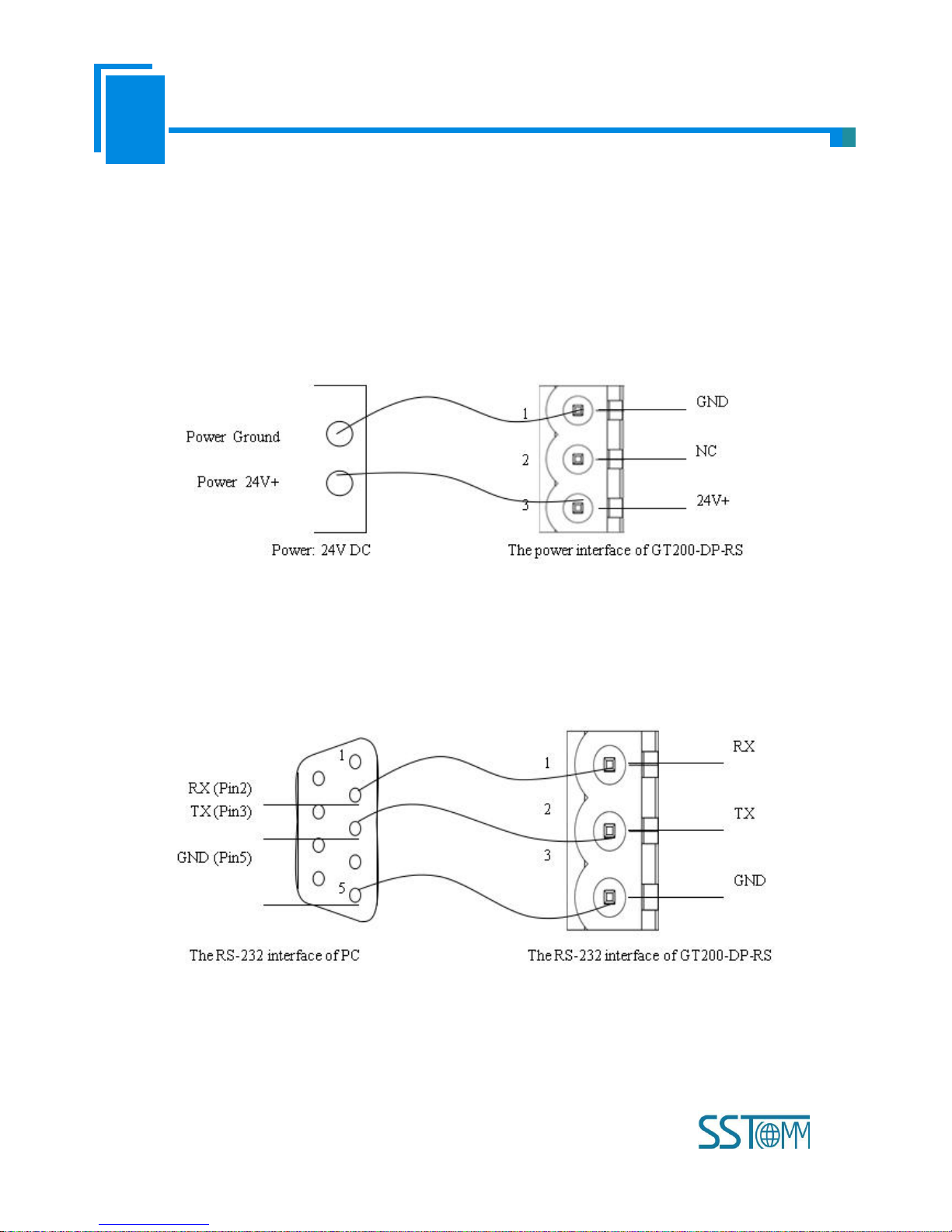
2.1 Power Wiring
The power is 24V DC, wiring method is shown as follow:
2.2 Wiring with PC
Establish the connection the RS-232 interface of gateway with PC, the wiring method is shown as follow:
2.3 Configuration Method
GT200-DP-RS V6.1 version product supports two methods to configure: One is through configuration software, the
Page 8
User Manual
Universal Serial/PROFIBUS DP Gateway
GT 200 -D P-R S
WWW.SSTCOMM.COM
8
other is through DP hardware configuration (this method is new added function of V6.X). It also supports USB and RS232
interface to configure. The LED Display of GT200-DP-RS will show in DP slave address and “-U” or “-P” alternately.
When showing “-U” on LED Display, the gateway is in the “Software configuration” state; When showing “-P”, it means
the gateway is in “DP Hardware Configuration” state.
1) When using “Setting through configuration software”, users can choose to use USB interface or RS-232 interface to
configure. If users use USB interface to configure it, they can download and upload the configuration under run and
configuration mode. USB interface can auto-detect and switch to the configuration mode. If users use RS-232 interface to
configure the gateway, GT200-DP-RS should be entered into configuration mode and finish upload and download tasks.
How to enter into configuration mode? Power on GT200-DP-RS, long press button for 5s, LED display shows CF blinking.
Click the button again to enter into configuration mode, LED display shows CF on.
Configuration software is named SST-MPG-CFG. Double click the application and install the configuration software
SST-MPG-CFG. Users can finish the installation lightly according to the wizard. Power on GT200-DP-RS, long press
button for 5s, LED display shows CF blinking. Click the button again to enter into configuration mode, LED display shows
CF on. Open the software SST-MPG-CFG and users can configure GT200-DP-RS.
2) Use “DP Hardware Configuration” way, first of all, users should confirm that LED display is showing “-P”, if it shows
“-P”, that means the gateway has been entered into “DP Hardware Configuration” status. Users can configure the gateway
in DP hardware configuration, no need to upload/download configuration in the software; If the LED display shows “-U”,
users should download the configuration that is “DP Hardware Configuration” in SST-MPG-CFG to let the gateway enter
into this mode, then users can use DP Hardware way to configure the gateway.
Page 9
User Manual
Universal Serial/PROFIBUS DP Gateway
GT 200 -D P-R S
WWW.SSTCOMM.COM
9
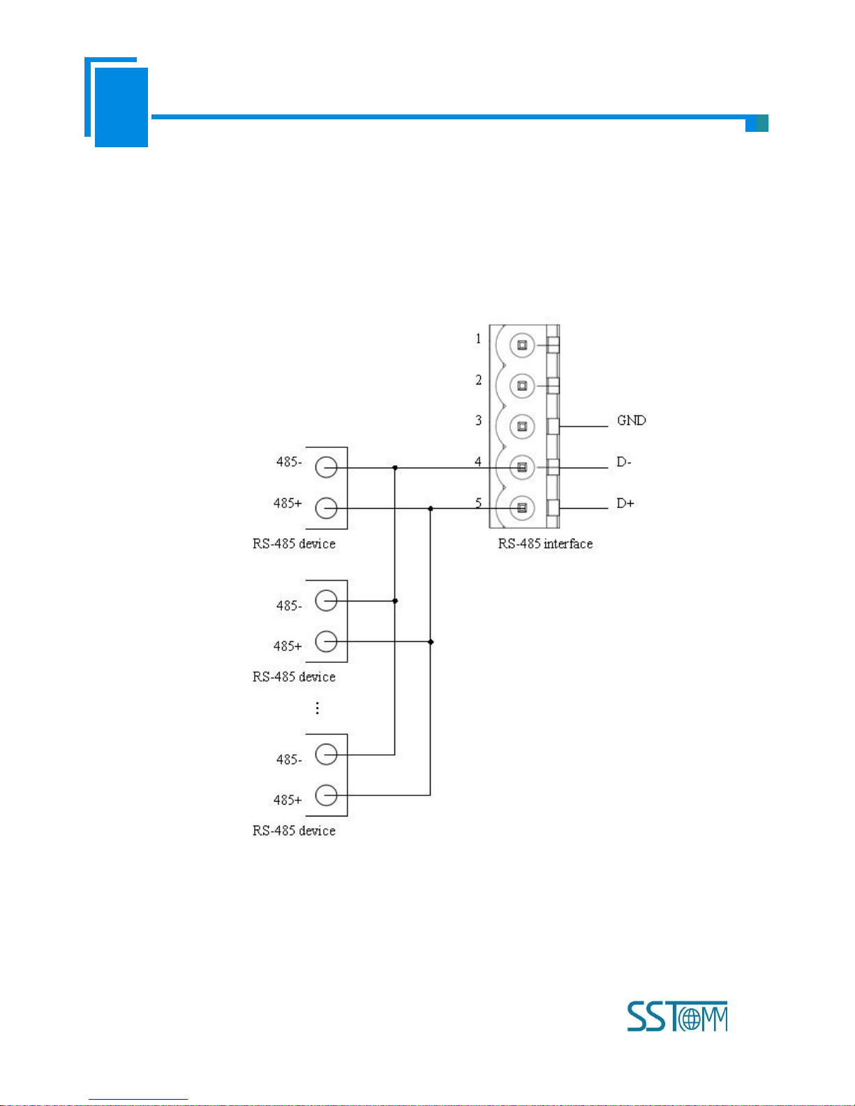
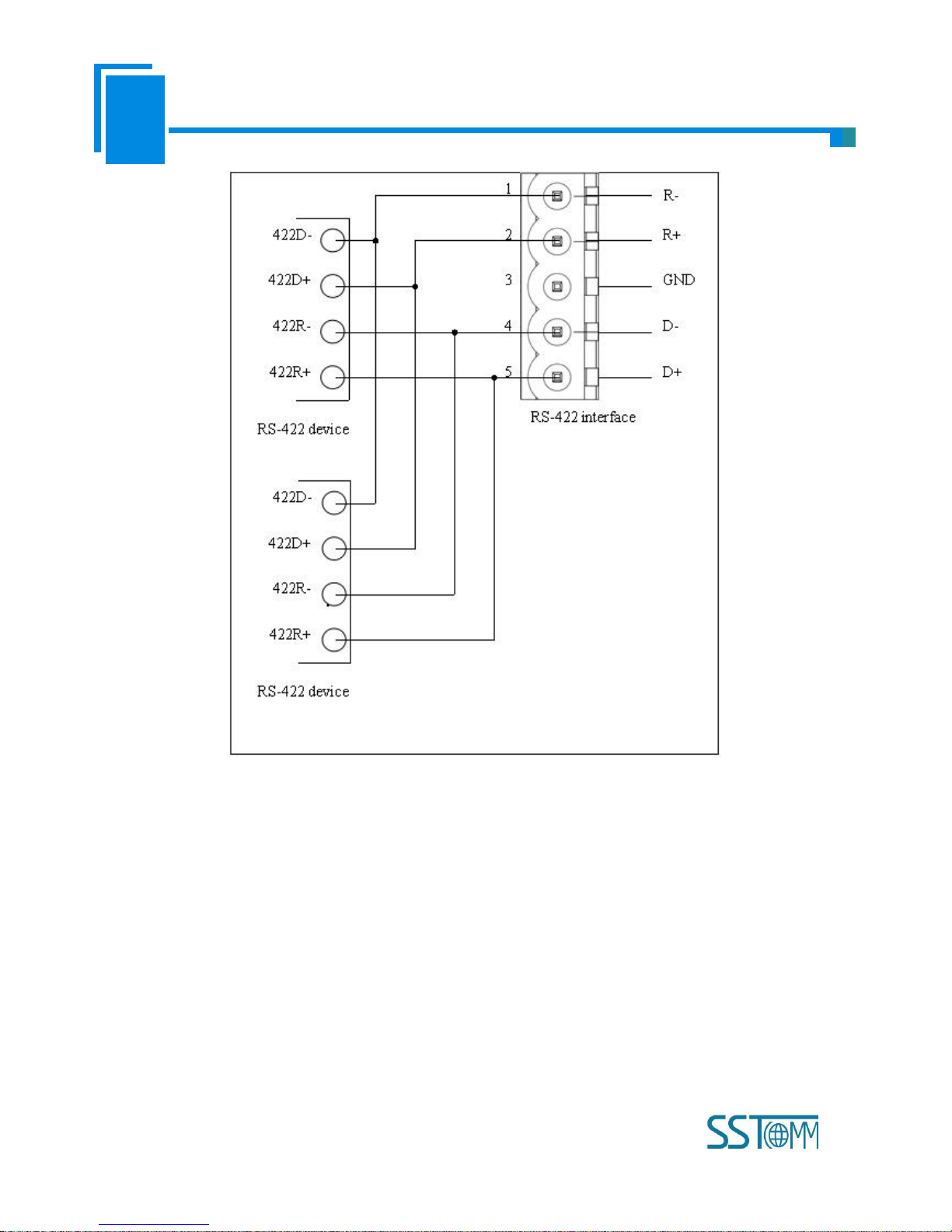
2.4 Wiring with Serial Device
After finishing configuration, wire communication interface, the wiring method of RS-232 is the same with "wiring
with PC", the wiring method of RS-485 is shown as follow:
The wiring method of RS-422 is shown as follow:
Page 10
User Manual
Universal Serial/PROFIBUS DP Gateway
GT 200 -D P-R S
WWW.SSTCOMM.COM
10
When RS-485 is in the communication of point to multi-point, to prevent the reflection and obstruction of signal, users
need to use two terminal resistances in furthest ports of line, and the parameters are 120Ω 1/2W.
Note: There is no terminal resistor inside RS-485 interface of GT200-DP-RS.
2.5 Wiring PROFIBUS DP Interface
Suggest wiring PROFIBUS DP with standard PROFIBUS DP connector. The description of PROFIBUS DP interface
has been shown in chapter 4.4.2.
Set the address of PROFIBUS DP through button on the panel.
Under normal run mode, LED display shows the address of PROFIBUS DP.
Register GSD file to PROFIBUS DP master configuration software (STEP7), and configure parameters.
Page 11

User Manual
Universal Serial/PROFIBUS DP Gateway
GT 200 -D P-R S
WWW.SSTCOMM.COM
11
PBF light being off and STA light being blinking show the connection with PROFIBUS DP master is successful!
2.6 Debug
GT200-DP-RS supports three operating modes: Modbus Master, Modbus Slave and User Config. GT200-DP-RS
supports debugging function in three modes. Quickly press the button for 3 times, GT200-DP-RS enter into debug mode,
the LED display shows “db” always on.
Notes: Under “Software Configuration” mode, the gateway can enter into Debug without DP master; Under “DP
Hardware Configuration” mode, the Debug function is enabled when connecting DP master, it is disabled without DP
master communication.
Page 12

User Manual
Universal Serial/PROFIBUS DP Gateway
GT 200 -D P-R S
WWW.SSTCOMM.COM
12
3 Hardware Descriptions
3.1 Product Appearance
Note: This picture is for reference only. Product appearance should accord to the real object.
Power Interface
RS-485/RS-422
Interface
RS-232 Interface
PROFIBUS DP
Interface
Indicators
LED Display
Button
USB Interface
Page 13
User Manual
Universal Serial/PROFIBUS DP Gateway
GT 200 -D P-R S
WWW.SSTCOMM.COM
13
3.2 Indicators
Indicators
State
Description
PB
PBF
Always Red
PROFIBUS DP communication fails.
Close
Communication is ok.
STA
Green Blinking
PROFIBUS DP is communicating.
Close
PROFIBUS DP is not communicating.
RS-232/485
/422
TX
Green Blinking
RS-485/422 port is sending data.
Close
RS-485/422 port isn't sending data.
RX
Green Blinking
RS-485/422 port is receiving data.
Close
RS-485/422 port isn't receiving data.
3.3 LED Display and Button
3.3.1 LED Display
LED display is in the front of the product.
There are three display conditions:
Page 14

User Manual
Universal Serial/PROFIBUS DP Gateway
GT 200 -D P-R S
WWW.SSTCOMM.COM
14
LED display
Description
CF
The gateway is in the configuration mode.
db
The gateway is in the debug mode.
Number+“-P” or
“-U” alternate
blinking
The gateway is in the run mode. The number shows the PROFIBUS DP slave
address. “-U” shows the gateway is in the “Software Configuration” mode; “-P”
shows the gateway is in the “DP Hardware Configuration” mode.
3.3.2 PROFIBUS DP Address Setting Button
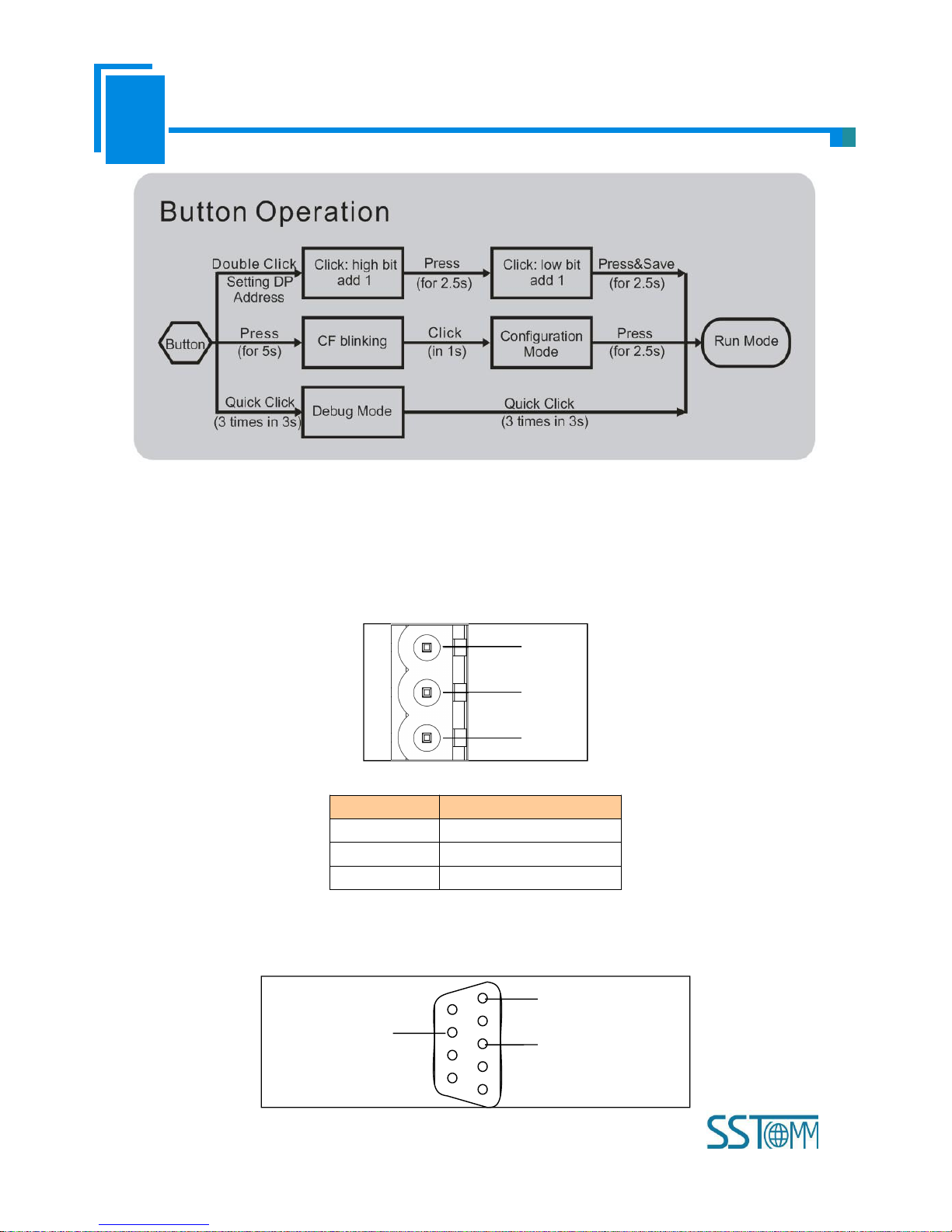
Configuration button on the front panel can be used to set the address of the PROFIBUS DP slave. Now, we have three
operation ways to provide users.
1) Under normal working condition of the GT200-DP-RS, digital tube always displays the address of the current
PROFIBUS DP address. Quickly press (double-click) the button twice in succession, the high bit starts flash, and the low bit
always on, click the button to add 1 to start setting the PROFIBUS DP address high bit. Long-press the button for 2.5
seconds, the high bit is always on, and the low bit starts flash. Click the button to add 1to start setting the PROFIBUS DP
address low bit. Then long-press the button for 2.5 seconds to save DP address.
2) Long press button for 5 seconds, LED display shows CF blinking, click button to enter into configuration state, the
LED display shows CF on, users can upload and download the configuration under this mode. When it is done, long press
2.5 seconds to enter into the run mode, the LED display shows DP address.
3) Quick click the button for three times in 3s to enter into debug mode, the LED display shows db is always on. Users
can do the serial debugging and other actions. When it is done, click the button three times in 3s to enter into the run mode,
the LED display shows DP address.
Notes: After entering into PROFIBUS DP address setting, the gateway will exit the address setting state automatically
and keep showing the original address without any action button within 10 seconds. The settable range of PROFIBUS DP
address is 0~99 (DEC).
The operation instruction of button is shown as below:
Page 15
User Manual
Universal Serial/PROFIBUS DP Gateway
GT 200 -D P-R S
WWW.SSTCOMM.COM
15
3.4 Interface
3.4.1 Power Interface
GNDNC24V+
1
2
3
Pin
Function
1
GND
2
NC(No Connect)
3
24V+, DC plus 24V
3.4.2 PROFIBUS DP Interface
5
1
PROFI_A (Pin 8)
GND (Pin 5)
PROFI_B (Pin 3)
Page 16
User Manual
Universal Serial/PROFIBUS DP Gateway
GT 200 -D P-R S
WWW.SSTCOMM.COM
16
PROFIBUS DP interface uses DB9 male-connector, and the pins are defined as follow:
Pin
Function
3
PROFI_B, Data positive
4
RTS
5
GND
6
+5VOutput
8
PROFI_A, Data negative
Bolt
SHIELD, Bus cable shield ground
PROFI_B (pin 3), PROFI_A (pin 8) and the shield GND (bolt) must be connected; RTS (pin 4) can be used to
determine the direction of transmission by equipment; +5 V (Pin 6) and GND (Pin 5) are used for the bus terminal, and can
also be used supply to fiber optic transceivers. The maximum output current of pin 5 and pin6 is 80mA.
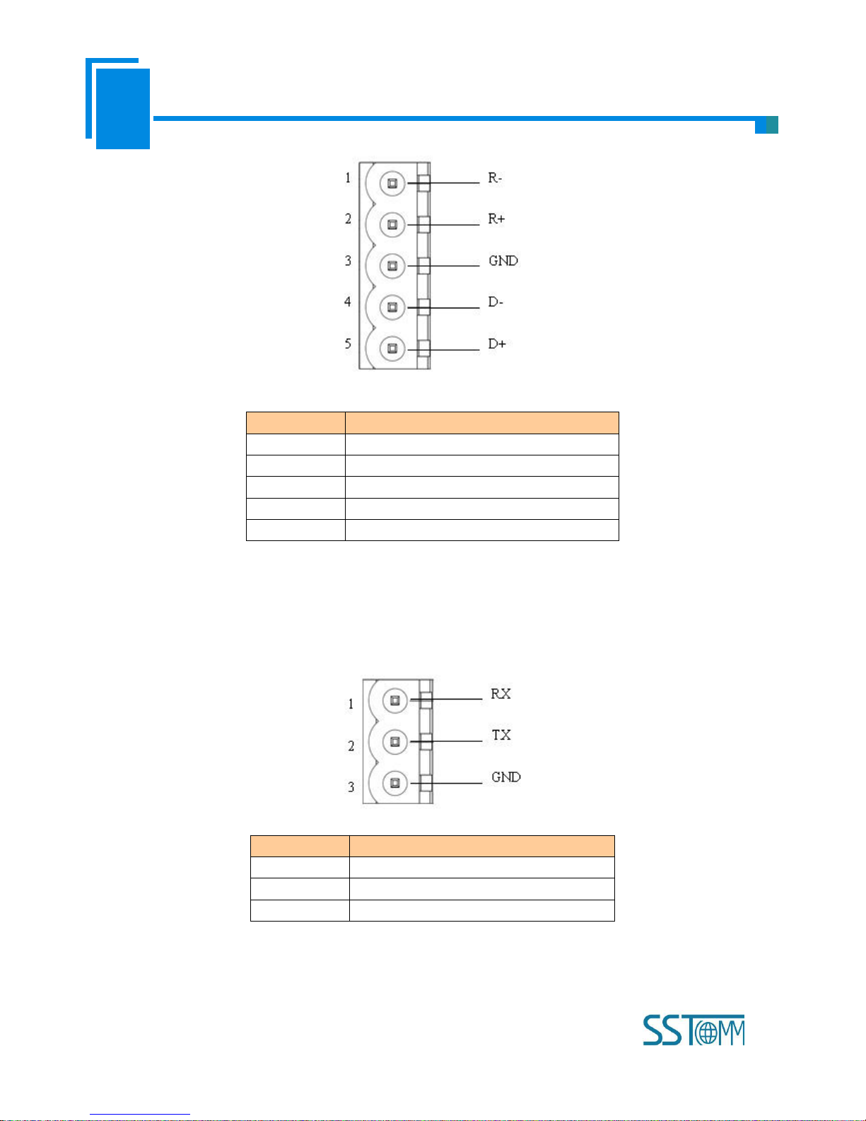
3.4.3 RS-485/RS-422 Interface
The RS-485 interface of GT200-DP-RS is standard, and the RS-485 characteristics of the product are shown as
follows:
1. The basic characteristics of RS-485 transmission technology
① Network topology: Linear bus, there are active bus termination resistors at both sides.
② Transfer rate: 300 bps~115.2Kbps.
③ Media: Shielded twisted-pair cable and also can cancel the shielding, depending on environmental conditions
(EMC).
④Site number: 32 stations per subsection (without repeater), and can up to 127 stations (with RS-485 repeater).
⑤Plug connection: 3-pin pluggable terminal.
2. The main points on RS-485 transmission equipment installation
①All the equipment be connected with RS-485 bus;
②Subsection can be connected up to 32 sites;
③The farthest end of each bus has a termination resistor—120Ω 1/2W to ensure reliable operation of the network.
Serial interface uses 5-pin pluggable terminal and users can wire it according to the wiring instructions on the panel.
Page 17
User Manual
Universal Serial/PROFIBUS DP Gateway
GT 200 -D P-R S
WWW.SSTCOMM.COM
17
Pin
Function
1
R-, RS-422 Receive Negative
2
R+, RS-422 Receive Positive
3
GND
4
D-, RS-485/RS-422 Transmit Negative
5
D+, RS-485/RS-422Transmit Positive
3.4.4 RS-232 Interface
RS-232 interface uses a 3-pin pluggable open terminal, and its pin description is shown as follows:
Pin
Function
1
RX, Connect user device RS-232's RX
2
TX, Connect user device RS-232's TX
3
GND, Connect user device RS-232's GND
Page 18
User Manual
Universal Serial/PROFIBUS DP Gateway
GT 200 -D P-R S
WWW.SSTCOMM.COM
18
4 Working Principle
4.1 Modbus Master
The data conversion between Modbus and PROFIBUS of GT200-DP-RS is established by mapping. GT200-DP-RS
has two data buffers, one is PROFIBUS network input buffer; the other is PROFIBUS network output buffer. Command ID
1, 2, 3 and 4 of Modbus puts the data read from Modbus slave station into network input buffer for reading by PROFIBUS
network; Command ID 5, 6, 15 and 16 of Modbus write the data from network output buffer into Modbus slave station.
Modbus
Device 1
Modbus
Device 2
Modbus
Device 3
Modbus
Device 4
Input buffer
Output buffer
Support 01H, 02H, 03H, 04H, 05H, 06H, 0FH, 10H function codes, when using “DP Hardware Configuration”, users
can configure 48 Modbus commands Module. When using “Software Configuration”, users can configure at most 100
Modbus commands in the software SST-MPG-CFG.
4.2 Modbus Slave
The data conversion between Modbus of GT200-DP-RS Modbus Slave and PROFIBUS is established by mapping
relation. GT200-DP-RS has two data buffers, one is PROFIBUS network input buffer, and the other is PROFIBUS network
output buffer. Network input and output buffers are relative to PROFIBUS. Modbus write-register commands write data
Page 19
User Manual
Universal Serial/PROFIBUS DP Gateway
GT 200 -D P-R S
WWW.SSTCOMM.COM
19
into network input buffer for PROFIBUS network reading. Modbus read-register commands data from network output
buffer, and transmit to Modbus master device through response messages.
PROFIBUS
Input buffer
4xxxx
00000 (40001)
00001 (40002)
00002 (40003)
… …
0xxxx
00000 (00001)
00001 (00002)
00002 (00003)
… …
PROFIBUS
Output buffer
3xxxx
00000 (30001)
00001 (30002)
00002 (30003)
… …
1xxxx
00000 (10001)
00001 (10002)
00002 (10003)
… …
Modbus write
commands: 06H
and 10H
Modbus read
commands: 03H
Modbus write
commands: 05H
and 0FH
Modbus read
commands: 01H
Modbus read
commands: 04H
Modbus read
commands: 02H
Support Modbus register address area 3 (3xxxx), area 4 (4xxxx), area 0 (0xxxx) and area 1 (1xxxx); and area 3
supports 04H function code; area 4 supports 03H, 06H, and 10H function codes; area 0 supports 01H, 05H, and 0FH
function codes; 1 area supports 02H function code.
PROFIBUS DP input buffer being relative to Modbus side is Modbus master output, mapping to Modbus holding
registers 4xxxx (10H and 06H commands are used to write data, 03H command is used to read back data) and loops 0xxxx
(0FH and 05H commands are used to write data, 01H command is used to read back data).
PROFIBUS DP output buffet being relative to Modbus side is Modbus master input, mapping to Modbus input
registers 3xxxx (04H command is used to read data) and input bits 1xxxx (02H command is used to read data).
Page 20
User Manual
Universal Serial/PROFIBUS DP Gateway
GT 200 -D P-R S
WWW.SSTCOMM.COM
20
5 Universal Mode
5.1 Data Exchange
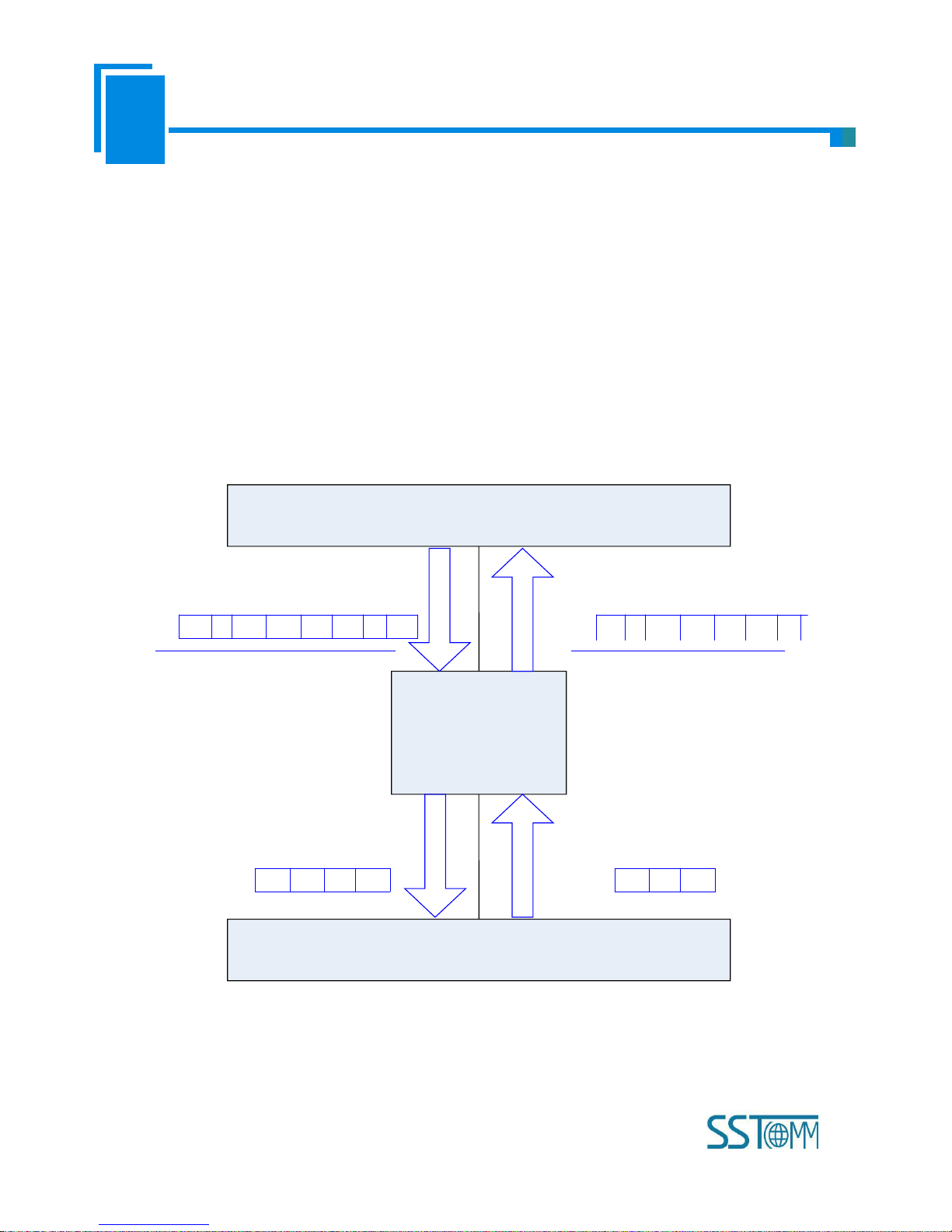
This product provides data communication between PROFIBUS DP and RS-485/RS-232. The communication between
PROFIBUS DP and RS-485/RS-232 is bidirectional. The output data of PROFIBUS DP can be sent to RS-485/RS-232
fieldbus through the interface of RS-485/RS-232 and the data received from RS-485/RS-232 is put into input data of
PROFIBUS DP. Data exchange is shown as follows:
Above, "EO" is transaction number of PROFIBUS output data; "i" is serial data number included in output data being
transmitted; "D1" to "Di" are data being transmitted by serial; "Ei" is transaction number of PROFIBUS input data; "j" is
serial data number included in input data receiving form serial; "D1" to "Dj" are data receiving form serial.
EoiD1D2…Di0
…
EijD1D2…Dj0
…
D1D2…DiD1…Dj
PROFIBUS
DP
RS
-485
/RS-232
GT200-DP-RS
PROFIBUS output data
PROFIBUS input data
Serial output data
Serial input data
Page 21

User Manual
Universal Serial/PROFIBUS DP Gateway
GT 200 -D P-R S
WWW.SSTCOMM.COM
21
5.2 Universal Protocol
PROFIBUS DP output data format:
[Transaction number][Length of serial output data n][Serial output data 1]… [Serial output data n] [0x00] … [0x00]
|— n —| |— m —|
Note:
The number of PROFIBUS DP output byte should be greater than or equal to n + 1;
M 0x00 are filling data (also for arbitrary number); n + m +1 should be equal to the number of PROFIBUS DP
output-byte.
Transaction number: When transmit output data; the transaction number must add 1 to show a new frame data.
Example:
If users select the number of PROFIBUS DP input byte and output-byte is 8-byte input and 8-byte output, length of
serial output-data is 3, data are 01 02 03. Current transaction number is 0.
The format of output-data is:
[01][03][01][02][03][00][00][00][00]
PROFIBUS DP input data format:
[Transaction number][Length of serial input data n] [Serial input data 1] … [Serial input data n] [0x00] … [0x00]
|— n —| |— m —|
Note:
The number of PROFIBUS DP input byte should be greater than or equal to n + 1;
M 0x00 are filling data (also for arbitrary number); n + m +1 should be equal to the number of PROFIBUS DP
input-byte.
Transaction number: The transaction number adds 1 showing a new frame input data.
Example:
Page 22

User Manual
Universal Serial/PROFIBUS DP Gateway
GT 200 -D P-R S
WWW.SSTCOMM.COM
22
If users select the number of PROFIBUS DP input-byte and output byte is 8-byte input and 8-byte output, length of
serial input-data is 3, data are 04 05 06. Current transaction number is 0.
The format of input data is:
[01][03][04][05][06][00][00][00][00]
Page 23
User Manual
Universal Serial/PROFIBUS DP Gateway
GT 200 -D P-R S
WWW.SSTCOMM.COM
23
6 Software Instructions
6.1 Notes before Configuring
SST-MPG-CFG is a product based on Windows platform, and it can set related parameters and commands of Modbus
and PROFIBUS DP of GT200-DP-RS.
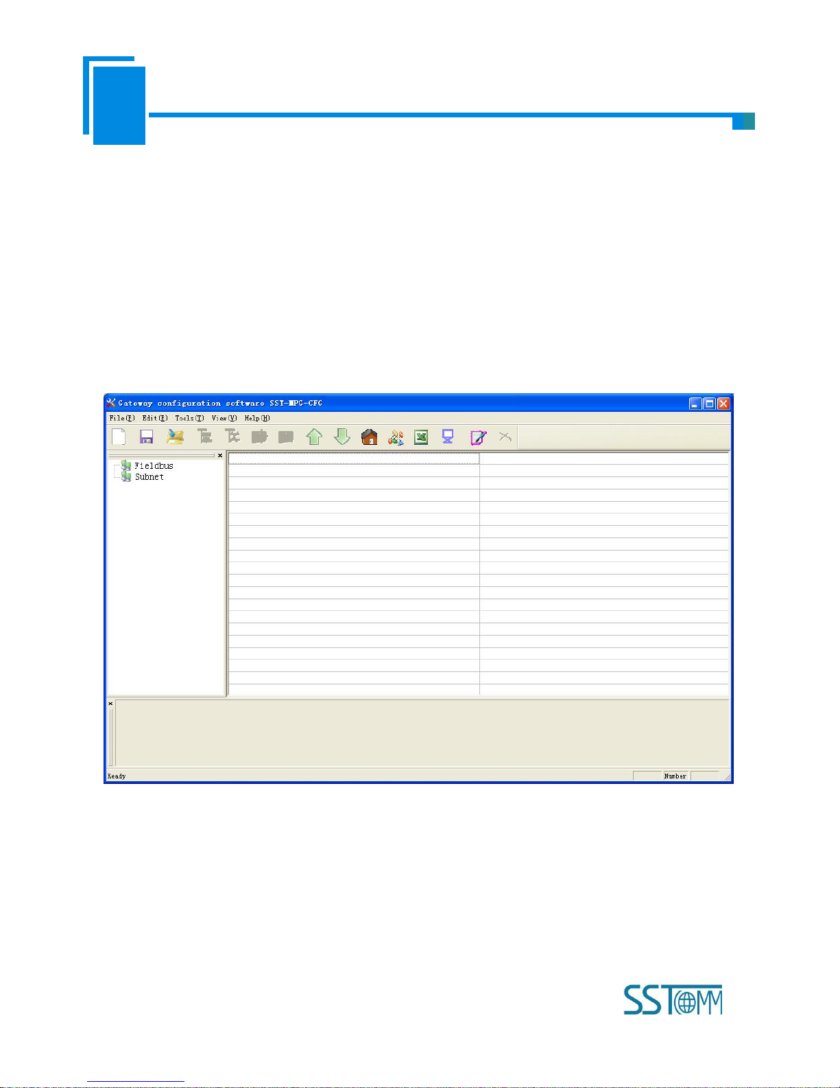
Double-click the icon to enter configuration interface:
6.2 User Interface
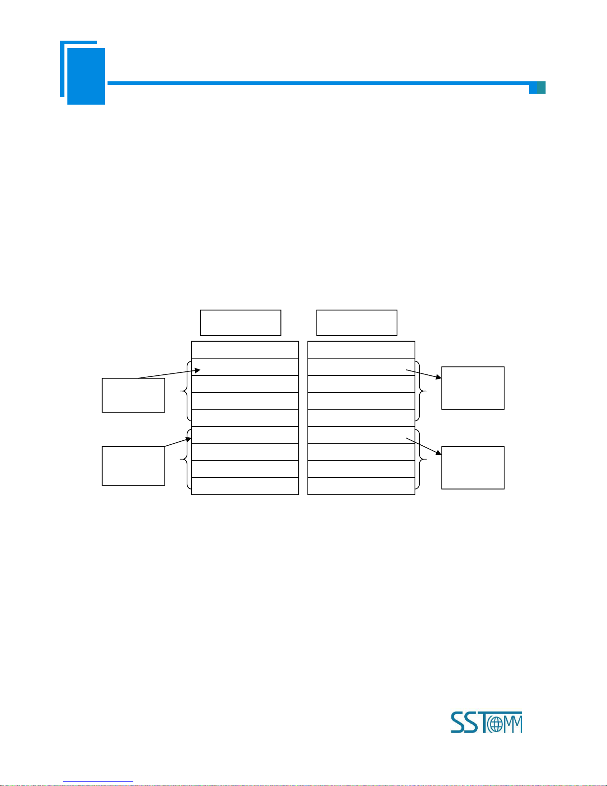
SST-MPG-CFG interface include: title bar, menu bar, toolbar, status bar, equipment section, configuration section and
notes section.
Note: All the gray part in the software cannot be modified.
Page 24
User Manual
Universal Serial/PROFIBUS DP Gateway
GT 200 -D P-R S
WWW.SSTCOMM.COM
24
Toolbar is shown as below:
Functions separately from left to right are: new, save, open, add nodes, delete nodes, add commands, delete commands,
upload configuration, download configuration, calculate mapping address, conflict detection, Export EXCEL, debug, edit
base address and cancel edit address.
New: Create a new configuration project
Save: Save the current configuration
Open: Open a configuration project
Add Nodes: Add a Modbus slave node
Delete Nodes: Delete a Modbus slave node
Equipment section: can
choose the operating
targets, including fieldbus
or sub-network and add
the nodes and
Menu bar
Toolbar
Title bar
Configuration section: input
configuration parameters, gray
part cannot be modified, while
white part can be modified.
Notes section: The specific
explanation to the nouns
appearing in the
configuration and devices to
help users to understand and
operate.
Page 25

User Manual
Universal Serial/PROFIBUS DP Gateway
GT 200 -D P-R S
WWW.SSTCOMM.COM
25
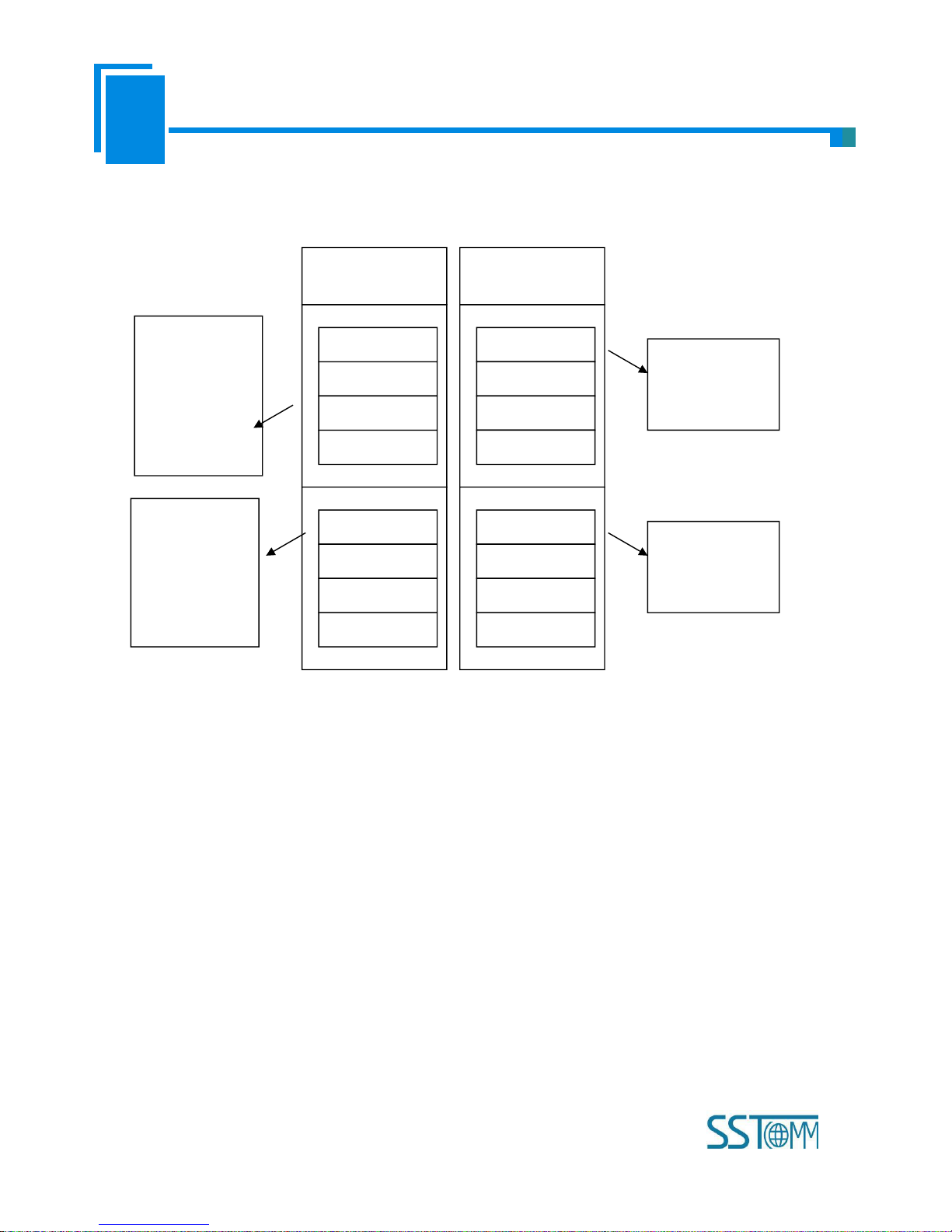
Add Commands: Add a Modbus command
Delete Commands: Delete a Modbus command
Upload Configuration: Read the configuration from the module and show it in the software
Download Configuration: Download the configuration from the software to the module
Calculate Mapping Address: Calculating mapping address automatically
Conflict Detection: Detect whether there is conflict in memory data buffer of the gateway
Export EXCEL: Export the current configuration to local hard disk and save it as .xls file
Debug: For debugging Modbus communications, and defining the network fault
Edit Base Address: Advanced function
Cancel Base Address: Advanced function
Page 26

User Manual
Universal Serial/PROFIBUS DP Gateway
GT 200 -D P-R S
WWW.SSTCOMM.COM
26
6.3 The Operation of Equipment View
6.3.1 Equipment View Interface
6.3.2 Operation Mode of Equipment View
The equipment view supports three types of operation: Edit Menu, Edit Toolbar and Right click edit Menu.
Page 27

User Manual
Universal Serial/PROFIBUS DP Gateway
GT 200 -D P-R S
WWW.SSTCOMM.COM
27
6.3.3 Operation Types of Equipment View
1) Add nodes: Right click on subnet or existing nodes, and then perform the operation of adding a new node. Then
there is a new node named "new node" under subnet.
2) Delete nodes: Right click on the node to be deleted, and then perform the operation of deleting the node. The node
and its all commands will be deleted.
3) Add commands: Right click on the node, and then perform the operation of adding command to add a command for
the node. The dialog box will be shown as follow:
Currently, it supports the commands: 01, 02, 03, 04, 05, 06, 15 and 16.
Select the command: Double click the command
4) Delete commands: Right-click on the command and then perform the operation of deleting the command.
5) Rename nodes: Left click on the node to be renamed, and then the edit status will be shown and you can rename it.
6) Copy node: Left click on the existing node, choose the node and execute the operation of copying nodes (include all
commands under the node)
7) Paste node: Left click and choose any existing node, execute operation of pasting node. Then under the subnet tree
you can see a new node (include all commands under the node); Parameters of new node is default setting, it needs to be
Page 28

User Manual
Universal Serial/PROFIBUS DP Gateway
GT 200 -D P-R S
WWW.SSTCOMM.COM
28
reset.
6.4 The Operation of Configuration View
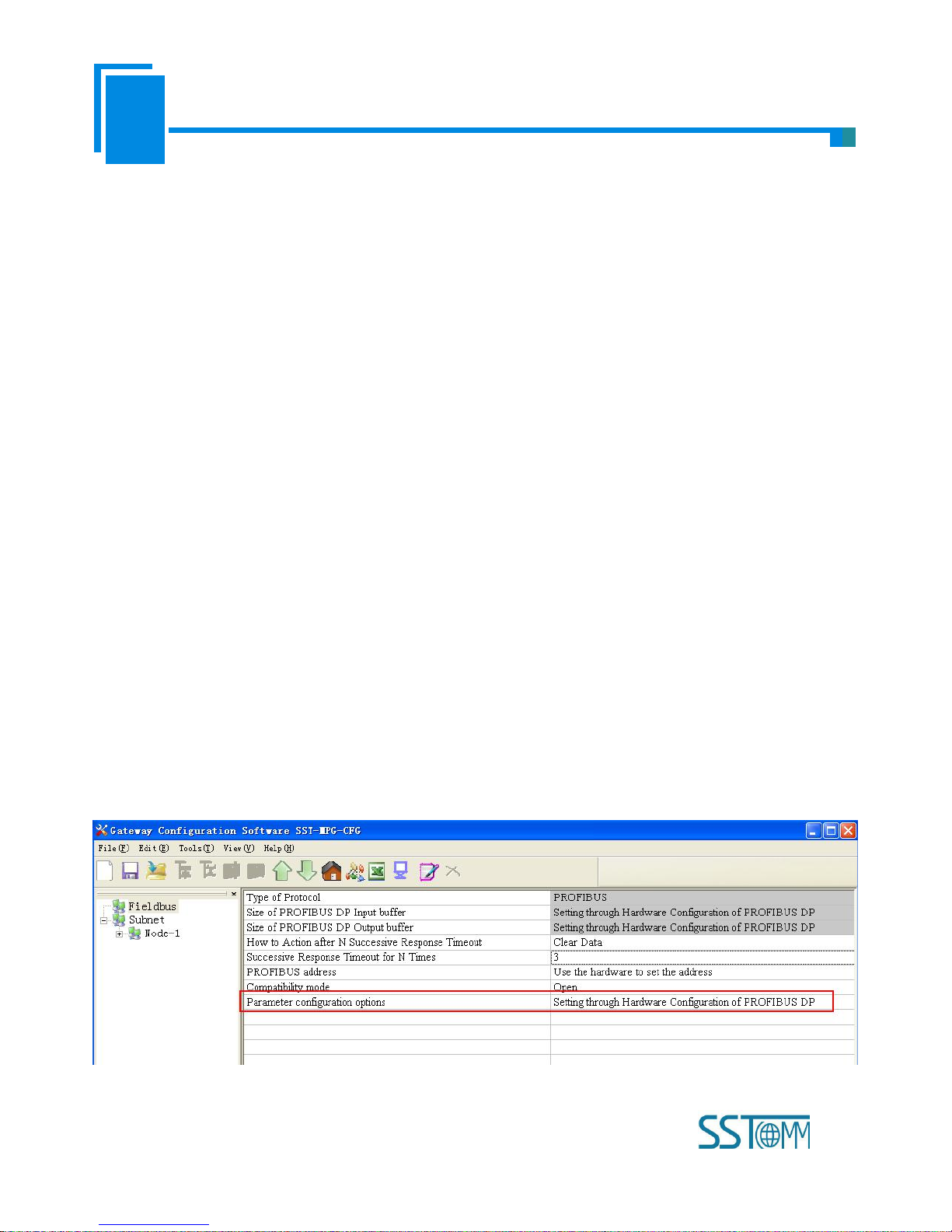
6.4.1 Interface of Fieldbus Configuration View
In the interface of device view, click fieldbus, and then the configuration view is shown as follows:
Configurable items include: "Type of Protocol", "Size of PROFIBUS DP Input buffer", "Size of PROFIBUS DP Input
buffer", "How to action after N successive response timeout", "Successive response timeout for N times", "PROFIBUS
address", "Compatliblity mode" and "Parameter configuration options".
Size of PROFIBUS DP Input buffer: Set in PROFIBUS DP master configuration software, cannot be modified;
Size of PROFIBUS DP Input buffer: Set in PROFIBUS DP master configuration software, cannot be modified;
How to action after N successive response timeout: Clear data or Hold data can be selected;
Successive response timeout for N times: 2 to 254 can be selected;
PROFIBUS address: Use the hardware to set the address or PROFIBUS address can be selected;
Compatliblity mode: Open or Close can be selected;
Parameter configuration options:Setting through configuration software or Setting through Hardware Configuration of
PROFIBUS DP can be selected.
Page 29

User Manual
Universal Serial/PROFIBUS DP Gateway
GT 200 -D P-R S
WWW.SSTCOMM.COM
29
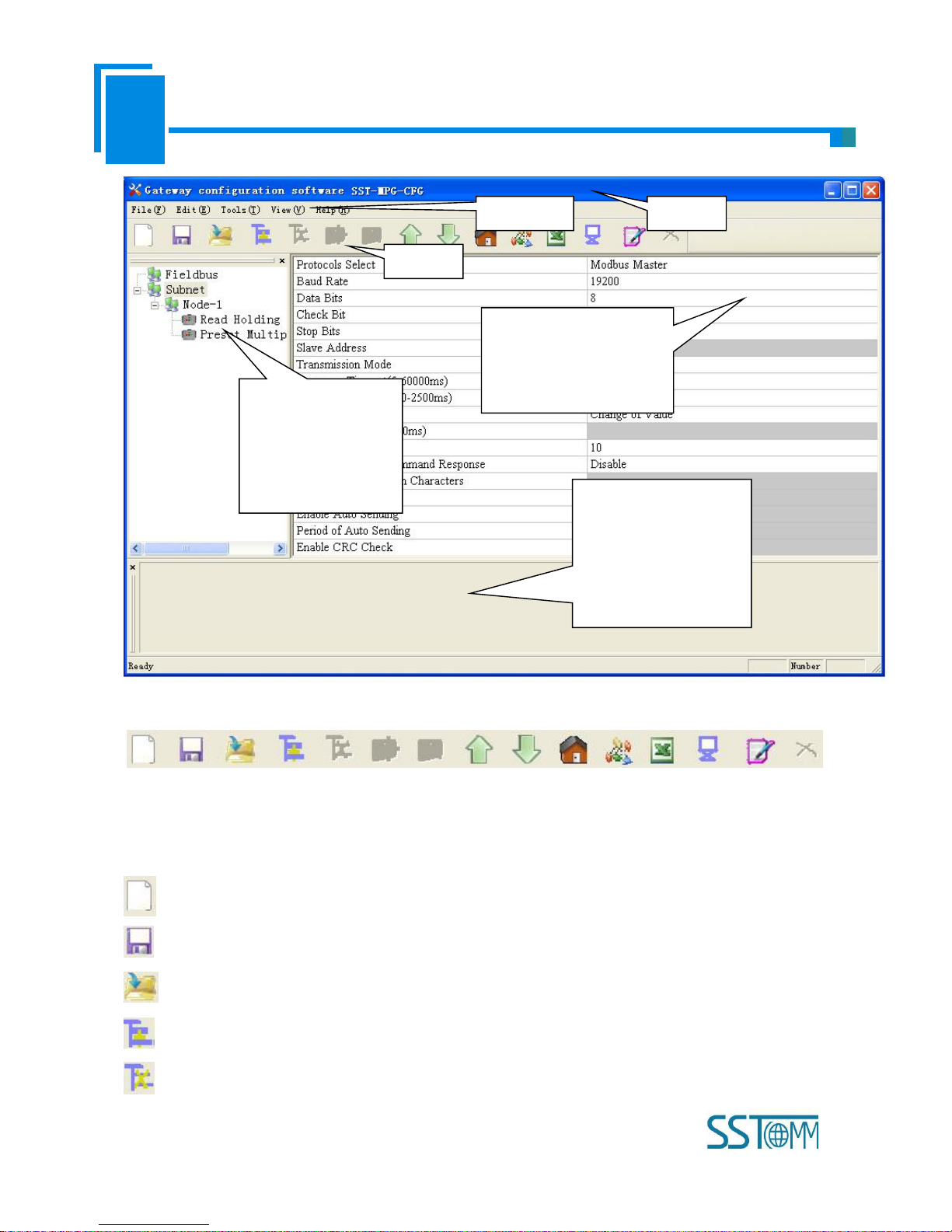
6.4.2 Interface of Subnet Configuration View
1) Choose Modbus Master in protocol type
Configurable parameters are shown as follows:
Baud Rate, Data Bits, Check Bit, Stop bit, Transmission mode, Response timeout, Delay between Polls, Output Mode,
Scan Rate, Status of Modbus Command Response, Communication interface, Time Interval between Character(Sending)
and Time Interval between Character(Receiving).
Interface of configuration view is shown as below:
Page 30

User Manual
Universal Serial/PROFIBUS DP Gateway
GT 200 -D P-R S
WWW.SSTCOMM.COM
30
Baud Rate: 300, 600, 1200, 2400, 4800, 9600, 19200, 38400, 57600 and 115200bps optional
Data bits: 8
Check Bit: none, odd, even, mark and space optional
Stop bits: 1, 2
Transmission mode: RTU, ASCII optional
Response timeout: When the Modbus master send commands, the time waiting for response from the slave, the range
is 5~60000ms.
Delay between polls: After one Modbus command has been sent and has received correct response, the delay time
before next command being sent, the range is: 0 ~ 2500ms.
Output Mode:
Modbus writing command (output command) has 3 kinds of outputting modes: Cycle, Forbidden and Change of Value
output.
Cycle: The same with Modbus read command, and output according to the scanning ratio.
Forbidden: Prohibit outputting Modbus write command.
Change of Value: When the output data has changed, it outputs the write command and stop outputting after receiving
Page 31

User Manual
Universal Serial/PROFIBUS DP Gateway
GT 200 -D P-R S
WWW.SSTCOMM.COM
31
correct response.
Scan rate: Ratio of slow scan and fast scan. If the fast scan command sends 10 times, slow scan command sends 1
time.
Status of Modbus Command Response: disable, 1byte, 2bytes, 3bytes, 4bytes, 5bytes, 6bytes, 7bytes, 8bytes, 9bytes,
10bytes, 11bytes, 12bytes and 13bytes can be selected. They locate in the first several bytes of PROFIBUS input data and
show the status of Modbus commands. The bit 0 of the first byte shows the status of the first Modbus command and six
bytes can show all status of 48 commands. The value of status is 0, when the communication is OK and the value is 1.
Communication interface: There are RS-232 and RS-485 to be selected. (Note: If using the RS-422, here select
RS-485)
Time interval between Characters (Sending): Serial port of GT200-DP-RS will send every byte according to the
time interval. The range of value is 0 to 600, and the unit is 0.1ms. If the value is 100, then the time interval is 100* 0.1 ms
=10ms. (Note: The time interval does not contain/cover the frame interval of Modbus protocol)
Time interval between Characters (Receiving): Serial port of GT200-DP-RS will use this time interval as the judge
receiving end basis. The range of value is 0 to 600, and the unit is 0.1ms. If the value is 100, then the time interval is 100*
0.1 ms =10ms. (Note: The time interval does not contain/cover the frame interval of Modbus protocol)
Note: The reference time of gateway receiving data and broking frame: Time interval between characters
(Receiving) + 3.5 character time of Modbus protocol. Make sure that the response wait time is greater than time
interval between characters + 3.5 character time.
2) Choose Modbus Slave in protocol type
Configurable parameters are shown as follows:
Baud Rate, Data Bits, Check Bit, Stops Bits, Slave Address, Transmission Mode, Communication Interface, Time
interval between Character (Sending) and Time Interval between Character (Receiving).
Interface of configuration view is shown as follow:
Page 32

User Manual
Universal Serial/PROFIBUS DP Gateway
GT 200 -D P-R S
WWW.SSTCOMM.COM
32
Baud Rate: 300, 600, 1200, 2400,4800, 9600, 19200, 38400, 57600 and 115200bps optional.
Data Bits: 8
Check Bit: none, odd, even, mark and space optional
Stop Bits: 1, 2
Slave Address: range is 0~247.
Transmission Mode: RTU, ASCII
Communication Interface: There are RS-232 and RS-485 to be selected. (Note: If using the RS-422, here select
RS-485)
Time interval between Characters (Sending): Serial port of GT200-DP-RS will send every byte according to the
time interval. The range of value is 0 to 600, and the unit is 0.1ms. If the value is 100, then the time interval is 100* 0.1 ms
=10ms. (Note: The time interval does not contain/cover the frame interval of Modbus protocol)
Time interval between Characters (Receiving): Serial port of GT200-DP-RS will use this time interval as the judge
receiving end basis. The range of value is 0 to 600, and the unit is 0.1ms. If the value is 100, then the time interval is 100*
0.1 ms =10ms. (Note: The time interval does not contain/cover the frame interval of Modbus protocol)
Page 33

User Manual
Universal Serial/PROFIBUS DP Gateway
GT 200 -D P-R S
WWW.SSTCOMM.COM
33
3) Choose User Config in protocol type:
Configurable parameters are shown as follows:
Baud Rate, Data Bits, Check Bit, Stop Bits, Frame Type, Time interval between Characters, Frame Length, Enable
Auto Sending, Period of Auto Sending, Enable CRC Check, Communication Interface, Time interval between Character
(Sending) and Time interval between Character (Receiving).
Interface of configuration view is shown as follow:
Baud Rate: 300, 600, 1200, 2400, 4800, 9600, 19200, 38400, 57600 and 115200bps optional
Data Bits: 8
Check Bit: none, odd, even, mark and space optional
Stop Bits: 1, 2
Frame Type: Time Interval between Characters, Frame length optional
Time interval between characters: It is maximum time interval between characters and used to decide whether a
frame is terminated or not. User input, the default is 10, and the range is 10 ~ 60000ms.
Frame Length: User input, the default is 111 and the range is 1 ~ 223, only valid when the frame type is frame length.
Page 34

User Manual
Universal Serial/PROFIBUS DP Gateway
GT 200 -D P-R S
WWW.SSTCOMM.COM
34
Enable Auto Sending: There are Enable and Disable to be selected.
Period of Auto Sending: User input, the default is 1000 and the range is 10 ~ 60000ms, only valid when the Enable
Auto Sending is Enabled
Enable CRC Check: Enable, Disable optional
Communication Interface: RS-232, RS-485 optional. (Note: If using the RS-422, here select RS-485)
Time interval between Characters (Sending): Serial port of GT200-DP-RS will send every byte according to the
time interval. The range of value is 0 to 600, and the unit is 0.1ms. If the value is 100, then the time interval is 100* 0.1 ms
=10ms. (Note: The time interval does not contain/cover the frame interval of Modbus protocol)
Time interval between Characters (Receiving): Serial port of GT200-DP-RS will use this time interval as the judge
receiving end basis. The range of value is 0 to 600, and the unit is 0.1ms. If the value is 100, then the time interval is 100*
0.1 ms =10ms. (Note: The time interval does not contain/cover the frame interval of Modbus protocol)
6.4.3 Interface of Node Configuration View
When the protocol type of subnet is "Modbus Master", in the interface of device view, left click a node, and then
configuration interface is shown as follow:
Page 35

User Manual
Universal Serial/PROFIBUS DP Gateway
GT 200 -D P-R S
WWW.SSTCOMM.COM
35
In the moment, you can modify the Modbus slave node address in the configuration view interface.
6.4.4 Interface of Command Configuration View
In the interface of device view, left click a command and then configuration interface is shown as follow:
Page 36

User Manual
Universal Serial/PROFIBUS DP Gateway
GT 200 -D P-R S
WWW.SSTCOMM.COM
36
Configurable parameters are shown as follows:
Starting Address, Number of Data, Mapping Address (HEX), Mapping Bit (0~7) and Type of Scan
Starting Address: The starting address of register or switching value or loop and so on in Modbus slave and the range
is 0~65535.
Notes: This address in SST-MPG-CFG is protocol address, when users input PLC address, it will pop up the below
dialog box after entering. After clicking OK, the PLC address users input will be converted into protocol address.
Following table shows the PLC address and corresponding protocol address examples:
Command
PLC address examples
Corresponding protocol address
Coil state
00001~00010
00000~00009
Input state
10001~10010
00000~00009
Holding register
40001~40010
00000~00009
Input register
30001~30010
00000~00009
Page 37

User Manual
Universal Serial/PROFIBUS DP Gateway
GT 200 -D P-R S
WWW.SSTCOMM.COM
37
Number of Data: number of register/switching value/coil in Modbus slave
Mapping address (HEX): The starting address of data in memory buffer of the module.
The address range of data mapping in the module memory:
Read command: 0x0000~ 0x00F3
Write command: 0x4000 ~ 0x40F3
When write command is used exchanging locally, it also can use: 0x0000 ~ 0x00F3
Mapping bit (0 - 7): For the bit operation commands, the position range of start-bit byte is 0 ~ 7
Data filter: There are three kinds of types: full word, high byte, low byte. Every register has two bytes. Full word
mapping is taking two bytes of register into gateway memory buffer; High byte mapping is taking the high byte of register
into gateway memory buffer; Low byte mapping is taking the low byte of register into gateway memory buffer.
Type of scan: There are two kinds of scanning mode: fast scan and slow scan. It is fit for requests of user about fast
scan or slow scan of different commands. Slow scan is equal to fast scan being multiplied by scan ratio. (Configure it in the
interface of subnet configuration interface)
Byte Swap: There are three kinds of types: no swap, double-byte swap and four-byte swap. Modbus function code
03H, 04H, 06H and 10H support different byte swap types.
6.4.5 Notes View
Notes view displays the explanation of configuration. The notes that show how to action after N successive response
timeout is shown as follow:
Page 38

User Manual
Universal Serial/PROFIBUS DP Gateway
GT 200 -D P-R S
WWW.SSTCOMM.COM
38
6.5 Conflict Detection
For the detection of whether there exists conflict of "the starting address of memory mapping", if conflict it can adjust
in time. The interface is shown as follow:
Page 39

User Manual
Universal Serial/PROFIBUS DP Gateway
GT 200 -D P-R S
WWW.SSTCOMM.COM
39
6.5.1 Operation of Command List
All the configuration commands can be shown at the command list. Each select box before command is used for
checking the memory-mapping location of that command. Click on the command can select the check box, and in the
memory-mapping area it can show the corresponding share of spatial location. Click the command again will remove the
selected box and it doesn’t show the mapping location. The function can be used to conflict detection of memory mapping
area.
Page 40

User Manual
Universal Serial/PROFIBUS DP Gateway
GT 200 -D P-R S
WWW.SSTCOMM.COM
40
6.5.2 Operation of Memory Mapping Area
Memory mapping area is divided two parts: input area and output area.
Input-mapping address: 0x0000 ~ 0x3FFF;
Output-mapping address: 0x4000 ~ 0x7FFF.
Each box represents a byte address.
Green: Read command show in the input-mapping area; no conflict;
Yellow: Write command show when the mapping addresses in the input area; no conflict;
Blue: When the address mapping area is located in the output area; no conflict.
Red: Output area or input area, different commands occupy the same byte address, the byte is shown as red.
For bit operation commands, the meanings of above shows are also applicable.
Click the input-output regional grid, whether the grid is occupied or not is shown as follows:
Page 41

User Manual
Universal Serial/PROFIBUS DP Gateway
GT 200 -D P-R S
WWW.SSTCOMM.COM
41
6.6 Hardware Communication
Hardware communications' menu items are shown as follow:
6.6.1 Serial Configuration
The software automatically scan the available serial port of system, and the available serial can be shown in serial list.
After modifying all items, pressing "OK" to save your settings.
Notes: Apart from the serial port number, the other parameters are fixed values: 19200, 8, N, 1.
Page 42

User Manual
Universal Serial/PROFIBUS DP Gateway
GT 200 -D P-R S
WWW.SSTCOMM.COM
42
6.6.2 Upload Configuration
Choose upload configuration, upload the gateway configuration information from the device to the software, the
display interface is shown as follows:
Note: Before uploading the configuration, please check whether the "serial port configuration" is the available port.
6.6.3 Download Configuration
Choose download configuration, download the configurated gateway information to the gateway, the display interface
Page 43

User Manual
Universal Serial/PROFIBUS DP Gateway
GT 200 -D P-R S
WWW.SSTCOMM.COM
43
is shown as follows:
Note 1: Before downloading the configuration, please check whether the "serial port configuration" is the available
port.
Note 2: Before downloading the configuration, make sure that all configurations has been completed.
6.7 Load and Save Configuration
6.7.1 Load Configuration Project
Choosing "Open" can save a project.
6.7.2 Save Configuration Project
Choosing "Save" can open a saved project before.
Page 44

User Manual
Universal Serial/PROFIBUS DP Gateway
GT 200 -D P-R S
WWW.SSTCOMM.COM
44
6.8 Export EXCEL
Excel document helps users to examine the configuration related.
Choose the icon , save the configuration as excel document and choose the right path.
Double click to open excel document, three modes as "Modbus master", "Modbus slave", "Universal mode" are
different from each other slightly.
Modbus master: The document has three parts: "Command List", "Fieldbus", and "Subnet".
Command list: Modbus command list 缺少图片
Fieldbus: Bus type and relevant parameters
Subnet: Modbus subnet parameters
As follows:
Modbus slave: The document has two parts: "Subnet" and "Fieldbus".
Subnet: Modbus subnet parameters
Fieldbus: Bus type and relevant parameters
As follows:
Universal mode: The document has two parts: "Subnet" and "Fieldbus".
Page 45

User Manual
Universal Serial/PROFIBUS DP Gateway
GT 200 -D P-R S
WWW.SSTCOMM.COM
45
Subnet: Modbus subnet parameters
Fieldbus: Bus type and relevant parameters
As follows:
6.9 Debug
This function is for debugging Modbus network communications, the interface is shown as follows:
Click Debug button will show up the firmware select dialog box, choose the matched version:
Page 46

User Manual
Universal Serial/PROFIBUS DP Gateway
GT 200 -D P-R S
WWW.SSTCOMM.COM
46
6.9.1 Debug Interface of 4.X or 3.X
Firmware Version of 4.X or 3.X only supports debug function in the protocol of "Modbus Master"
Status: shows communication state with slave: response ok, response timeout, response abnormal and response error
Slave Address: slave address in the configuration file (HEX)
Starting Address: "Modbus register starting address" (HEX) in the configuration file
Data/Exception Code: display the slave data or exception code (HEX)
Memory mapping address: Starting address of data writing in the gateway
Data: Data writing into the gateway
When Modbus has no response or response timeout:
Page 47

User Manual
Universal Serial/PROFIBUS DP Gateway
GT 200 -D P-R S
WWW.SSTCOMM.COM
47
When Modbus responses are right:
Page 48

User Manual
Universal Serial/PROFIBUS DP Gateway
GT 200 -D P-R S
WWW.SSTCOMM.COM
48
After filling the "Memory mapping address" and "Data" correctly, users can click on "Send" button to transmit the
packet.
Page 49

User Manual
Universal Serial/PROFIBUS DP Gateway
GT 200 -D P-R S
WWW.SSTCOMM.COM
49
User clicks on the "Save Content" button can save the received data to a computer's hard disk.
6.9.2 Debug Interface of 5.x and above
Modbus master:
Page 50

User Manual
Universal Serial/PROFIBUS DP Gateway
GT 200 -D P-R S
WWW.SSTCOMM.COM
50
Status: shows communication state with slave: respond correctly, response timeout, respond abnormally and response
error
Slave Address: slave address in the configuration file (only master, HEX)
Function Code (Command): Modbus command in the configuration file (only master, HEX)
Starting Address:"Modbus register starting address" (HEX) in the configuration file (only master, HEX)
Data/Exception Code: display the slave data or exception code (HEX)
Notes: When the gateway is configured as Modbus master, it will show slave address, function code and starting
address.
Read Data: show the latest read data (HEX)
Memory mapping address: Starting address of data writing in the gateway
Data: Data writing into the gateway
When users want to fill in correct "memory mapping address" and "data", you can click "send" button to send the
Page 51

User Manual
Universal Serial/PROFIBUS DP Gateway
GT 200 -D P-R S
WWW.SSTCOMM.COM
51
package out.
Save Content/Stop Saving: the software supports saving data to local disk. When saving is over, users need to click
"Stop Saving" to save it.
Stop Displaying/Continue to Display: the software supports dynamic or static data debugging.
Clear Data: click this button, it will clear the data in the debug interface.
Stop debug and exit: click the button or the exit button to close the debug interface.
Exit: Force quit.
When Modbus has response timeout:
When Modbus slave responses are right:
Page 52

User Manual
Universal Serial/PROFIBUS DP Gateway
GT 200 -D P-R S
WWW.SSTCOMM.COM
52
The debug interface of user config and Modbus slave:
Page 53

User Manual
Universal Serial/PROFIBUS DP Gateway
GT 200 -D P-R S
WWW.SSTCOMM.COM
53
The debug function of user config and slave is send input buffer data and output buffer data of PROFIBUS to the
debug interface alternately, users can send debug data to simulate the input data of PROFIBUS.
Page 54

User Manual
Universal Serial/PROFIBUS DP Gateway
GT 200 -D P-R S
WWW.SSTCOMM.COM
54
7 PROFIBUS DP Hardware Configuration Instructions
GT200-DP-RS V6.X version has four GSD files, "Software Configuration" has a corresponding GSD file, and “DP
Hardware Configuration” has three corresponding GSD files. As follows:
DPRS2V60A.GSD-Configuration software configuration mode use
DPRS2V60M.GSD-DP Hardware Configuration of Modbus master
DPRS2V60S.GSD-DP Hardware Configuration of Modbus slave
DPRS2V60T.GSD-DP Hardware Configuration under universal mode
It needs to import the GSD file in the PROFIBUS DP master configuration software, and then set the relevant
parameters. Take the following Step7 configuration software as an example:
7.1 Register GSD file
Open an existing project in STEP 7, under the Hardware configuration interface, click Options->Install GSD file,
Figure 1:
The popup interface is shown as Figure 2, select GSD file needs to be installed, click “Install GSD File”, and click
“Close” after registering completely, close the register window.
Page 55

User Manual
Universal Serial/PROFIBUS DP Gateway
GT 200 -D P-R S
WWW.SSTCOMM.COM
55
In the menu, select Options -> Update Catalog, update the registered devices in the device catalog
You can find the registered device in the right window /PROFIBUS DP/Additional Field Devices/General/Converter/,
shown as Figure 4:
Page 56

User Manual
Universal Serial/PROFIBUS DP Gateway
GT 200 -D P-R S
WWW.SSTCOMM.COM
56
7.2 DPRS2A.GSD-Configuration software configuration mode use
After registering DPRS2A.GSD completely, you can find GT200-DP-RS V6.0 device in the catalog .In the
SST-MPG-CFG configuration mode, GT200-DP-RS achieves the functions of the three types of protocols, which are
Modbus master, Modbus slave, Universal mode. and perform data exchange between serial port and DP master.
In the Step7 configuration, GT200-DP-RS offers Module numbers up to 64, Max Input 244 bytes, Max Output 244 bytes,
Max Input or Output 488Bytes.
Module
Integrity
4 Words Input,4 Words Output
word
8 Words Input,8 Words Output
word
24 Words Input,24 Words Output
word
56 Words Input,56 Words Output
word
1 Byte Input
byte
1 Word Input
word
2 Words Input
word
4 Words Input
word
8 Words Input
word
16 Words Input
word
Page 57

User Manual
Universal Serial/PROFIBUS DP Gateway
GT 200 -D P-R S
WWW.SSTCOMM.COM
57
32 Words Input
word
64 Words Input
word
2 Words Input Consistent
length
4 Words Input Consistent
length
8 Words Input Consistent
length
16 Words Input Consistent
length
1 Byte Output
byte
1 Word Output
word
2 Words Output
word
4 Words Output
word
8 Words Output
word
16 Words Output
word
32 Words Output
word
64 Words Output
word
2 Words Output Consistent
length
4 Words Output Consistent
length
8 Words Output Consistent
length
16 Words Output Consistent
length
GT200-DP-RS supports data including word complete, byte complete, and length complete
The user selects the data block as long as it is not less than the number of bytes transmitted. who can select one or more
data block.
7.3 DPRS2M.GSD-DP Hardware Configuration of Modbus master
After registering DPRS2M.GSD completely, you can find GT200-DP-RS Modbus Master V6.0 device in the catalog.
That is to say GT200-DP-RS act as a Modbus master at the side of Modbus.
Page 58

User Manual
Universal Serial/PROFIBUS DP Gateway
GT 200 -D P-R S
WWW.SSTCOMM.COM
58
PROFIBUS DP slave property parameter:
In configuration interface, double click “GT200-DP-RS Modbus Master V6.0” in PROFIBUS DP network, the popup
property interface is shown as follow:
Configurable parameters include:
Baud rate (bps): Configure serial baud rate, 300, 600, 1200, 2400, 4800, 9600, 19200, 38400, 57600, 115200bps can
be selected;
Data bits, Parity bit, Stop bits: 8 None 1, 8 Odd 1, 8 Even 1, 8 Mark 1, 8 Space 1 and 8 None 2 can be selected;
Protocol Type: If what you drag to the PROFIBUS DP bus is “GT200-DP-RSModbus Master”, the parameter is
“Modbus Master”, if what you drag to the PROFIBUS DP bus is “GT200-DP-RS Modbus Slave”, the parameter is
“Modbus Slave”.
Response Timeout: It is available when “Protocol Type” is Modbus Master, 100, 200, 300, 400, 500, 600, 700, 800,
900, 1000, 1500, 2000, 3000, 4000, 5000ms can be selected.
Delay Between Polls: It is available when “Protocol Type” is Modbus Master, No Delay, 50, 100, 150, 200, 300, 400,
500, 600, 700, 800, 900, 1000, 1500, 2000ms can be selected.
Transmission Mode: Set Modbus transmission mode, RTU or ASCII can be selected.
Write Mode: Set output mode, Change of value or Cycle can be selected.
Page 59

User Manual
Universal Serial/PROFIBUS DP Gateway
GT 200 -D P-R S
WWW.SSTCOMM.COM
59
Response Timeout Action: Enter Data, Clear / Hold Data, default state is Hold Data;
Response Timeout for N times: the number of over times, the input range: 2-254, the default value is 3;
Communication Interface: communication interface, RS485 and RS232 can be chosen, the default is RS485.
Module Parameter
GT200-DP-RS Modbus Master supports modules include: Control Module, Status Module, Exception Module,
Read Module, Write Module.
■ The module set as Modbus command is Read Module, Write Module, as follows:
Read Module : (Modbus Read Command) Read 1-8 Bits(0xxxx)~Read 249-256 Bits(0xxxx), Read 1-8
Bits(1xxxx)~Read 249-256 Bits(1xxxx), Read 1 Words(4xxxx)~Read 64 Words (4xxxx), Read 2
Words(4xxxx)Consistent~Read 16 Words(4xxxx)Consistent, Read 1 Words(3xxxx)~Read 64 Words(3xxxx), Read 2
Words(3xxxx)Consistent~Read 16 Words(3xxxx)Consistent
Write Module : (Modbus Write Command)Write Single Bits(0xxxx)~Write 249-256 Bits(0xxxx), Write Single
Words(4xxxx)~Write 64 Words(4xxxx), Write 2 Words(4xxxx)Consistent~Write 16 Words(4xxxx)Consistent~Write 64
Words(4xxxx), Write 2 Words(4xxxx)Consistent~Write 16 Words(4xxxx)Consistent
(No. 3 area is the function code 04H; No. 4 area is the function code 03H, 06H, 10H; No. 0 area is the function
code 01H, 05H, 0FH; No. 1 area is the function code 02H.)
In configuration interface, double-click Module that is already dragged to the left bottom of the GT200-DP-RSrelevant
table, the popup interface is shown as follow:
Page 60

User Manual
Universal Serial/PROFIBUS DP Gateway
GT 200 -D P-R S
WWW.SSTCOMM.COM
60
Configurable parameters include:
Slave address: Set Modbus slave address which is needed to connect with GT200-DP-RS, 1 to 247 can be selected;
Function: No need to set, every function code has its own module;
Starting Address: Set register starting address, 0~65535 can be selected;
No. of Points: Number of data, only those modules that are relevant with 01H, 02H, 0FH function codes need to set
the number of data;
Other Module like Control Module, Stats Module and Exception Module are shown below:
Control Module:Control (8 Commands) ~ Control (48 Commands)
As a Modbus master, users can control the transmission of Modbus command from the PROFIBUS terminal, the
provided 6 control Module can be selected, every GT200-DP-RS only can be configured one control Module.
Notes: if no need of the control Modbus command, the control Module is no need to configure, Modbus
command can send automatically.
Control (8 Commands) ~ Control (48 Commands): Select one kind control from 6, every bit of the control block
control 1 Modbus command. When the enable is needed, set 1 to the corresponding bit; otherwise, set 0.
Page 61

User Manual
Universal Serial/PROFIBUS DP Gateway
GT 200 -D P-R S
WWW.SSTCOMM.COM
61
a) Control (8 Commands): Control the transmitting of the 8 commands which is after the slots occupied by the
Control Module, it occupies 1 byte of the output area.
b) Control (16 Commands): Control the transmitting of the 16 commands which is after the slots occupied by the
Control Module, it occupies 2 bytes of the output area.
c) Control (24 Commands): Control the transmitting of the 24 commands which is after the slots occupied by the
Control Module, it occupies 3 bytes of the output area.
d) Control (32 Commands): Control the transmitting of the 32 commands which is after the slots occupied by the
Control Module, it occupies 4 bytes of the output area.
e) Control (40 Commands): Control the transmitting of the 40 commands which is after the slots occupied by the
Control Module, it occupies 5 bytes of the output area.
f) Control (48commands): Control the transmitting of the 48 commands which is after the slots occupied by the
Control Module, it occupies 6 bytes of the output area.
Notes: When users add the control block, the control block should be added in front of the slots which occupied by
Read Module and Write Module.
For example:
If users need to configure 7 commands (7 read/write data block) during actual using process, then you can select
control block “Control (8 Commands)”, which means the control commands numbers of the selected “Control Module”
should be equals or more than the numbers of the configured commands.
Assume the data block of PROFIBUS DP master slots is shown as below:
After powering on the gateway, if the communication of PROFIBUS DP is normal (STA green light blinking), users
need to evaluate the output address QB0 to enable the required sending command. If only the 2nd (Read 1-8bits (1xxxx) )
Page 62

User Manual
Universal Serial/PROFIBUS DP Gateway
GT 200 -D P-R S
WWW.SSTCOMM.COM
62
and the fourth (Read 8 Words (3xxxx) ) command need to be configured by enable, set 1 to the 2nd bit and 4th bit of the
first byte in output area. That means evaluate the output address QB0 as 9 (00001001).
Status Module: Status (8 Commands) ~ Status (48 Commands), Exception Codes
As a Modbus master, PROFIBUS side can monitor the status of Modbus commands, and provide two kinds of method
to monitor Modbus commands status:
Status (8 Commands) ~ Status (48 Commands): Select one kind status from 6, and every bit means the status of every
Modbus command respectively. The value is 1 when response is correct, and when times of abnormal response, timeout or
error count up to 3 the value is 0. The count clears when response is right.
a) Status (8 Commands): Monitoring 8 commands
b) Status (16 Commands): Monitoring 16 commands
c) Status (24 Commands): Monitoring 24 commands
d) Status (32 Commands): Monitoring 32 commands
e) Status (40 Commands): Monitoring 40 commands
f) Status (48 Commands): Monitoring 48 commands
Exception codes: 1 word Module, can monitor the executive condition of Modbus commands
High byte indicates Modbus command index 0~47, low byte indicates abnormal code or error code. When response is
correct, error code is 0, when response is abnormal or overtime or error, the highest bit of high byte is set to 1. Abnormal
code come from devices, the error code is 0xFF when response overtime or error.
7.4 DPRS2S.GSD-DP Hardware Configuration of Modbus slave
After registering DPRS2S.GSD completely, you can find GT200-DP-RS Modbus Master V6.0 device in the catalog.
That is to say GT200-DP-RS act as a Modbus slave at the side of Modbus.
Page 63

User Manual
Universal Serial/PROFIBUS DP Gateway
GT 200 -D P-R S
WWW.SSTCOMM.COM
63
PROFIBUS DP slave property parameter:
In configuration interface, double click “GT200-DP-RS Modbus Slave V6.0” in PROFIBUS DP network, the popup
property interface is shown as follow:
Configurable parameters include:
Baud rate (bps): Configure serial baud rate, 300, 600, 1200, 2400, 4800, 9600, 19200, 38400, 57600, 115200bps can
be selected;
Data bits, Parity bit, Stop bits: 8 None 1, 8 Odd 1, 8 Even 1, 8 Mark 1, 8 Space 1 and 8 None 2 can be selected;
Page 64

User Manual
Universal Serial/PROFIBUS DP Gateway
GT 200 -D P-R S
WWW.SSTCOMM.COM
64
Protocol Type: If what you drag to the PROFIBUS DP bus is “GT200-DP-RSModbus Master”, the parameter is
“Modbus Master”, if what you drag to the PROFIBUS DP bus is “GT200-DP-RS Modbus Slave”, the parameter is
“Modbus Slave”.
Slave Address: When Protocol Type is Modbus Slave, configure the slave address of GT200-DP-RS, 1~247 can be
selected.
Transmission Mode: Set Modbus transmission mode, RTU or ASCII can be selected.
Communication Interfaces: RS458 and RS232 can be selected, the defautl is RS485..
Module Parameter
GT200-DP-RS Modbus slave supports modules include: Status Module, Input Module, Output Module.
■ The module set as Modbus command is Input module and Output Module, as follows:
Input Module : (Modbus Read Command) 8 Bits Input(0xxxx)~128 Bits Input(0xxxx), 1 Word Input (4xxxx)~64
Words Input (4xxxx), 2 Words Input(4xxxx)Consistent~16 Words Input(4xxxx)Consistent
Output Module : (Modbus 写 命 令)8 Bits Input(1xxxx)~128 Bits Input(1xxxx), 1 Word Input(3xxxx)~64 Words
Input(3xxxx), 2 Words Input(3xxxx)Consistent~16 Words Input(3xxxx)Consistent
(No. 3 area is the function code 04H; No. 4 area is the function code 03H, 06H, 10H; No. 0 area is the function
code 01H, 05H, 0FH; No. 1 area is the function code 02H.)
In configuration interface, double-click Module that is already dragged to the left bottom of the GT200-DP-RSrelevant
table, the popup interface is shown as follow:
Page 65

User Manual
Universal Serial/PROFIBUS DP Gateway
GT 200 -D P-R S
WWW.SSTCOMM.COM
65
Function: When draging one Module, the function is fixed. It means this function includes 03H (3), 06H (6) and
10H(16).:
Other Module: Stats Module is shown below:
Status Module: As modbus slave, PROFIBUS can monitor Modbus network status, PROFIBUS side can provide
Modbus network status Module, which occupies one byte. When slave receives one correct request, the status byte add 1.
7.5 DPRS2T.GSD-DP Hardware Configuration of Universal Mode
After registering DPRS2T.GSD completely, you can find GT200-DP-RS Modbus Serial V6.0 device in the catalog.
That is to say GT200-DP-RS executes the function of universal mode, which can connect self-defined protocol serial
devices..
Page 66

User Manual
Universal Serial/PROFIBUS DP Gateway
GT 200 -D P-R S
WWW.SSTCOMM.COM
66
PROFIBUS DP slave property parameter:
In configuration interface, double click “GT200-DP-RS Modbus Slave V6.0” in PROFIBUS DP network, the popup
property interface is shown as follow:
Configurable parameters include:
Baud rate (bps): Configure serial baud rate, 300, 600, 1200, 2400, 4800, 9600, 19200, 38400, 57600, 115200bps can
Page 67

User Manual
Universal Serial/PROFIBUS DP Gateway
GT 200 -D P-R S
WWW.SSTCOMM.COM
67
be selected;
Data bits,Parity bit,Stop bits:Configuration data bits, test mode and stop bits, 8 None 1, 8 Odd 1, 8 Even 1, 8 Mark
1, 8 Space 1, 8 None 2 Optional;
Protocol Type:Serial, which means "universal mode", cannot be changed;
Receiving Frame Type : There are two control modes for serial receive data. "Time Interval Between Characters"
(character timed out) and "Frame Length" (character number)are available. Character timeout: by judging the time interval
between characters and characters to determine the end of a frame of serial data; number of characters: by determining the
number of characters to determine the end of a frame of serial data.
Interval Between Characters (ms): Character Timeout: The maximum time interval between characters and
characters in general mode.
Frame Length: Number of characters: In general mode, the serial port receives the number of data frame characters.
Valid only if the control mode is a number of characters.
Enable Auto Sending(ms): Auto send, with "On" and "Off" optional, the default is "off". "Open": send the serial data,
according to the automatic send cycle to send serial data. "Off", according to the general mode output rule output data.
Period of Auto Sending (ms): Automatic transmission period, the serial port automatically send data cycle. Valid only
when "Enable Auto Sending (ms): Auto Send" is on.
Enable CRC Check: CRC check, with "On" and "Off" optional, the default is "off". "Open": when serial send data, it
will automatically add two bytes of CRC checksum; when serial data receive dataf, it will automatically determine if the
CRC check code is normal, and in the PROFIBUS input data automatically remove the two bytes of CRC Check code.
Communication Interface: communication interface, RS485 and RS232 optional, the default is RS485.
Communication Interface: communication interface, RS485 and RS232 optional, the default is RS485.
Input Data Effective Length: PROFIBUS input valid data length, with "on" and "off" optional, the default is "off".
"ON": The first byte of the PROFIBUS input data is used to indicate the length of the serial data frame received. "Off": No
byte represent data length in the PROFIBUS input data.
Module parameter
GT200-DP-RS works as a common mode, supports Module include: Input Module and Output Module. Input Module
is used to store the contents of the GT200-DP-RS read from the serial device, Output Module is used to store the data
Page 68

User Manual
Universal Serial/PROFIBUS DP Gateway
GT 200 -D P-R S
WWW.SSTCOMM.COM
68
content of the PROFIBUS DP master output to the serial device. Only set the PROFIBUS DP input / output address, no
other parameters need to be set.
Page 69

User Manual
Universal Serial/PROFIBUS DP Gateway
GT 200 -D P-R S
WWW.SSTCOMM.COM
69
8 Installation
8.1 Machine Dimension
Size: 0.98 in (width)*3.94 in (height)*3.54 in (depth)
8.2 Installation Method
Using 35mm DIN RAIL
Page 70

User Manual
Universal Serial/PROFIBUS DP Gateway
GT 200 -D P-R S
WWW.SSTCOMM.COM
70
Page 71

User Manual
Universal Serial/PROFIBUS DP Gateway
GT 200 -D P-R S
WWW.SSTCOMM.COM
71
Appendix A: Using STEP 7 to Set PROFIBUS DP
The following show how to use STEP7 to configure GT200-DP-RS:
First of all, copy *. Gsd file to the following path: Step7\S7data\gsd\
1. Open SIMATIC Manager ; Figure 1:
Figure 1
2. Open File, and then New, create a new project; Figure 2:
Figure 2
3. Click Insert, Station and then SIMATIC 300 Station; Figure 3
Page 72

User Manual
Universal Serial/PROFIBUS DP Gateway
GT 200 -D P-R S
WWW.SSTCOMM.COM
72
Figure 3
4. Open S7 PLC hardware configuration
Open SIMATIC 300(1) and then double-click Hardware; Figure 4
Figure 4
5. In the menu, select Options and Install GSD file, Update GSD in the device catalog
Page 73

User Manual
Universal Serial/PROFIBUS DP Gateway
GT 200 -D P-R S
WWW.SSTCOMM.COM
73
Figure 5
6. Here you can find your equipment in the right side of the window ; Figure 6
Page 74

User Manual
Universal Serial/PROFIBUS DP Gateway
GT 200 -D P-R S
WWW.SSTCOMM.COM
74
Figure 6
7. Set PLC rack, click the "Hardware Catalog \ SIMATIC 300 \ RACK-300 \ Rail"; Figure 7
Page 75

User Manual
Universal Serial/PROFIBUS DP Gateway
GT 200 -D P-R S
WWW.SSTCOMM.COM
75
Figure 7
8. Set CPU module and select the corresponding device type and the occupied slots.
9. Create PROFIBUS DP network and set up PROFIBUS DP: Click New and then Network settings, select DP; select a
baud rate such as 187.5Kbps, then "OK". Double-click it; Figure 8
Page 76

User Manual
Universal Serial/PROFIBUS DP Gateway
GT 200 -D P-R S
WWW.SSTCOMM.COM
76
10. Select PROFIBUS DP Master address; Figure 9:
Figure 9
Page 77

User Manual
Universal Serial/PROFIBUS DP Gateway
GT 200 -D P-R S
WWW.SSTCOMM.COM
77
11. Put configuration into PROFIBUS DP network, and map the input and output data block into other controller’s
memory; Figure 10:
Figure 10
Operation is divided into two steps, the first step is dragging GT200-DP-RS into the network configuration on the
upper left, the mouse will change shape, and that is to say, it can be placed. The second step is dragging data block into the
data mapping table at the bottom left, mapping to the PLC memory.
Note: PROFIBUS input and output bytes of GT200-DP-RSare set in PROFIBUS master configuration software. The
max number of modules is 64 when configuring Step7. The max number of input bytes is 244, the max number of
output bytes is 244 and the max number of input bytes add output bytes is 488.
Note: The address must be the same with the settings of module switch!
12. Compile and download into PLC.
Page 78

User Manual
Universal Serial/PROFIBUS DP Gateway
GT 200 -D P-R S
WWW.SSTCOMM.COM
78
Appendix B: How STEP7 Access Data of Gateway and
Select Data Module
How STEP7 Access Data of Gateway
GT200-DP-RS provides Modules shown as follow. The max number of modules is 64 when configuring Step7. The
max number of input bytes is 244, the max number of output bytes is 244 and the max number of input bytes add output
bytes is 488.
Module
Integrity
4 Words Input, 4 Words Output
Word
8 Words Input, 8 Words Output
Word
24 Words Input, 24 Words Output
Word
56 Words Input, 56 Words Output
Word
1 Byte Input
Byte
1 Word Input
Word
2 Word Input
Word
4 Word Input
Word
8 Word Input
Word
16 Word Input
Word
32 Word Input
Word
64 Word Input
Word
2 Word Input Consistent
Total Length
4 Word Input Consistent
Total Length
8 Word Input Consistent
Total Length
16 Word Input Consistent
Total Length
1 Byte Output
Byte
1 Word Output
Word
2 Word Output
Word
4 Word Output
Word
8 Word Output
Word
16 Word Output
Word
32 Word Output
Word
64 Word Output
Word
Page 79

User Manual
Universal Serial/PROFIBUS DP Gateway
GT 200 -D P-R S
WWW.SSTCOMM.COM
79
2 Word Output Consistent
Total Length
4 Word Output Consistent
Total Length
8 Word Output Consistent
Total Length
16 Word Output Consistent
Total Length
Above, the modules of GT200-DP-RS include: word consistent, byte consistent and total length.
For modules which support word and byte as its consistent, users can apply "MOVE" command to read and write data
in Step7 programming.
For modules which support total length as its consistent, users can apply "SFC 14" to read data and "SFC 15" to write
data in Step 7 programming.
How STEP7 Select Data Module
Generally, when the module includes "consistent", it means the module with total length as its consistent, such as "2
words Input Consistent". When you choose the module, you must use "SFC 14" to access the data address. When a data of
Page 80

User Manual
Universal Serial/PROFIBUS DP Gateway
GT 200 -D P-R S
WWW.SSTCOMM.COM
80
Modbus slave is two-word data, and need high accuracy and real-time, users generally select "2 words Input Consistent",
and do not select "2 words Input". When PLC read data it access the data module through "SFC14", and it can prevent data
jump in process of data transmission.
The selection varies for user’s need of different bytes. Such as: When users need 20-word input ( The data number of
PLC reading form Modbus slave is 20), users can select input modules that are greater than or equal to "20 word input"
module (32words Input, 64words Input…) or input and output modules that are greater than or equal to "20 word input"
module (56 words Input, 56words Output…).
 Loading...