

Page 1
Embedded EtherNet/IP Module
GS11-EI
User Manual
REV 1.3
SST Automation
E-mail: SUPPORT@SSTCOMM.COM
WWW.SSTCOMM.COM
Page 2

User Manual
Embedded EtherNet/IP Module
GS11-EI
Catalog
1. About the Module.................................................................................................................................................3
1.1 General............................................................................................................................................................3
1.2 Features...........................................................................................................................................................3
1.3 Specifications..................................................................................................................................................3
2. Hardware...............................................................................................................................................................5
2.1 Appearance..................................................................................................................................................... 5
2.2 Indicators........................................................................................................................................................ 5
2.3 Interface.......................................................................................................................................................... 5
2.3.1 Ethernet Interface................................................................................................................................ 5
2.3.2 Host Interface...................................................................................................................................... 6
2.4 UART Baud Rate............................................................................................................................................7
2.5 Reset Signal.................................................................................................................................................... 8
3. Communication Protocol......................................................................................................................................9
3.1 Description......................................................................................................................................................9
3.2 The GS11-EI Communication Flowchart and User Program........................................................................ 9
3.3 Real-time monitoring IP function.................................................................................................................10
3.4 Initialize Communication............................................................................................................................. 11
3.5 User-defind Protocol.....................................................................................................................................12
4. Dimension........................................................................................................................................................... 14
5. Development Board............................................................................................................................................16
5.1 Appearance................................................................................................................................................... 16
5.2 Function........................................................................................................................................................ 16
5.2.1 RS232 Interface.................................................................................................................................16
5.2.2 Baudrate Setting Switch....................................................................................................................17
5.2.3 Reset Key...........................................................................................................................................18
5.2.4 LED....................................................................................................................................................18
6. Configuration Software...................................................................................................................................... 19
6.1 SST-EIP-CFG Introduction..........................................................................................................................19
6.2 Search Equipment.........................................................................................................................................20
6.3 IP Search.......................................................................................................................................................20
6.4 Advanced Configuration.............................................................................................................................. 21
6.5 User Parameter Configuration......................................................................................................................26
7. Configuration Software(EemTest)..................................................................................................................... 30
7.1 Overview.......................................................................................................................................................30
7.2 User Interface................................................................................................................................................30
7.3 Establish/Disconnect Connection.................................................................................................................31
7.4 Receive/Transmit Data................................................................................................................................. 34
8. Precautions of Operation and Maintenance....................................................................................................... 36
Appendix: How to Read and Write I/O Data............................................................................................................. 37
1. Use I/O Method to Read and Write Data................................................................................................... 37
2. Use MSG Method to Read and Write Data................................................................................................42
1
Page 3

User Manual
Embedded EtherNet/IP Module
GS11-EI
Read I/O Data............................................................................................................................................. 42
Write I/O Data............................................................................................................................................ 46
2
Page 4

User Manual
Embedded EtherNet/IP Module
GS11-EI
1. About the Module
Upgrade your UART or serial device to EtherNet/IP device expediently
Ethernet is 10/100M adaptive
Supports EtherNet/IP Class 1 and Class 3 connections
Provide dedicated configuration software, User-friendly configuration.
Setting the IP address via the UART( Optional Features)
[1]. Support the EtherNet/IP communication protocol that follow ODVA standard.
[2]. GS11-EI provides one Ethernet port and one UART interface (included in the 20-pin connector), can realize
[3]. Ethernet is 10/100M adaptive
[4]. The size of input and output buffers can be set by users:
[5]. As an EtherNet / IP server on the Ethernet side, can support 1 EtherNet / IP client to communicate at the
[6]. The serial interface is UART, half duplex, 8 data bits, one stop bit, and no parity, and support 2400,
1.1 General
GS11-EI is an embedded EtherNet/IP module and provides instant EtherNet/IP connectivity via the host
interface which is SST defined. Any device that supports the host interface can communicate with GS11-EI
through UART.
1.2 Features
1.3 Specifications
the EtherNet / IP data and serial data conversion;
The size of input buffer is 256 bytes at most
The size of output buffer is 256 bytes at most
same time, the minimum data update rate is 5ms;
4800,9600, 19200, 38400, 57600, 115200, 230400 baud rate
3
Page 5

User Manual
Embedded EtherNet/IP Module
GS11-EI
[7]. Serial port use user-defind protocol, easy to realize serial port communication.
[8]. Power: +3.3VDC (3.14 ~ 3.45V), 190mA
[9]. Environmental temperature: -40 ~ 85℃, humidity: 5% ~ 90%
[10].Dimension (W*H*D): 0.88 in*0.95 in*1.46 in (22.6mm*24.2mm*37.2mm).
4
Page 6

User Manual
Embedded EtherNet/IP Module
GS11-EI
2. Hardware
Indicator
Status
Description
Green
Off
No network connection
Always on
Have network connection
Yellow
Off
No network data transmitting or receiving
Blinking
Have network data transmitting or receiving
Network activity
indicator
Network connecting
indicator
PIN8
PIN1
2.1 Appearance
2.2 Indicators
2.3 Interface
2.3.1 Ethernet Interface
The Ethernet interface uses an 8-line RJ-45 interface, and the pin definitions are as follows:
5
Page 7
User Manual
Embedded EtherNet/IP Module
GS11-EI
Pins
Signals
Descriptions
Pin 1
TXD+
Transmit Data+
Pin 2
TXD-
Transmit Data-
Pin 3
RXD+
Receive Data+
Pin 4
BID+
Bi-directional Data+
Pin 5
BID-
Bi-directional Data-
Pin 6
RXD-
Receive Data-
Pin 7
BID+
Bi-directional Data+
Pin 8
BID-
Bi-directional Data-
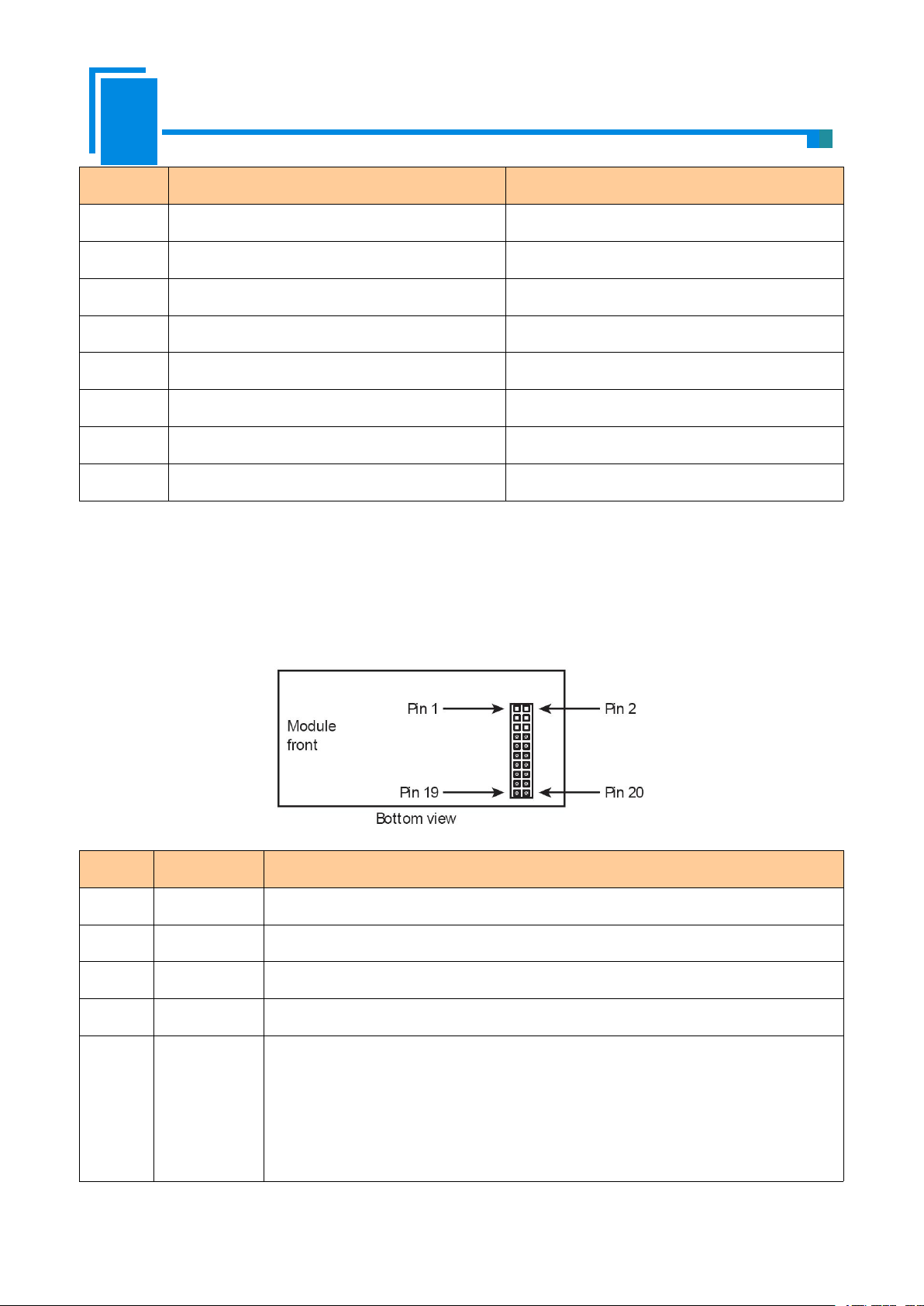
2.3.2 Host Interface
Pins
Signals
Description
1 ~ 6
NC
Reserved
7
RXD
UART Receive (Input), connect with TXD of host processor or MCU
8
TXD
UART Transmit (Output), connect with RXD of host processor or MCU
9
GPIO
Reserved
10
/RUN
The status of GS11-EI (Output), and need a 10K pull-up resistor on user board.
Logic 1: The GS11-EI module is in starting.
Logic 0: The module’s start has been completed. (Include waiting for initialization
state, start the EtherNet/IP protocol stack and data exchange state, etc.)
GS11-EI has a 20-pin socket connector (needle-type), including power, UART and GPIO. The pin position
and definition are as follows:
6
Page 8
User Manual
Embedded EtherNet/IP Module
GS11-EI
If this pin is pull down to low voltage before starting the module (by using a 1K
pull-down resistor), the module will start with default IP address (192.168.0.11), and
this mode is only used to update the firmware.
11
BAUD2
Set the UART baud rate (Input), see the following table.
12
BAUD1
13
BAUD0
14
/RESET
Reset signal (Input), Active low.
15
+3.3V
+3.3V DC power Supply
16
GND
GND power Supply
17 ~ 19
NC
Reserved
20
/DATAEXCH
Data Exchange (Output), and need a 10K pull-up resistor on the user board.
Logic 1: The module is in non-data exchange state (such as start state, waiting for
initialization state, start the EtherNet/IP protocol stack, etc.)
Logic 0: The module is ready for data exchange.
2.4 UART Baud Rate
Index
BAUD2
BAUD1
BAUD0
Baud Rate(bps)
00002400
10014800
20109600
301119200
410038400
510157600
6110115200
7111230400
UART baud rate settings are as follows:
7
Page 9

User Manual
Embedded EtherNet/IP Module
GS11-EI
2.5 Reset Signal
GS11-EI RESET (Pin 14) is hardware reset signal input. When the RESET pin is pulled down to GND or low
to 2.88V lasting for 1 millisecond, the module will be forced to reset, and the host must wait for 250 milliseconds
(typical value, after reset the module), and then the host must check the PIN10 (/RUN) and PIN20
(/ DATAEXCH). If the two pins are Logic 0, then the host can exchange data.
8
Page 10
User Manual
Embedded EtherNet/IP Module
GS11-EI
3. Communication Protocol
GS11-EI
user -defined
EtherNet/IP
Request1
Request2
Request…
Request a
Request b
Request…
Response1
Response2
Response…
Response a
Response b
Response…
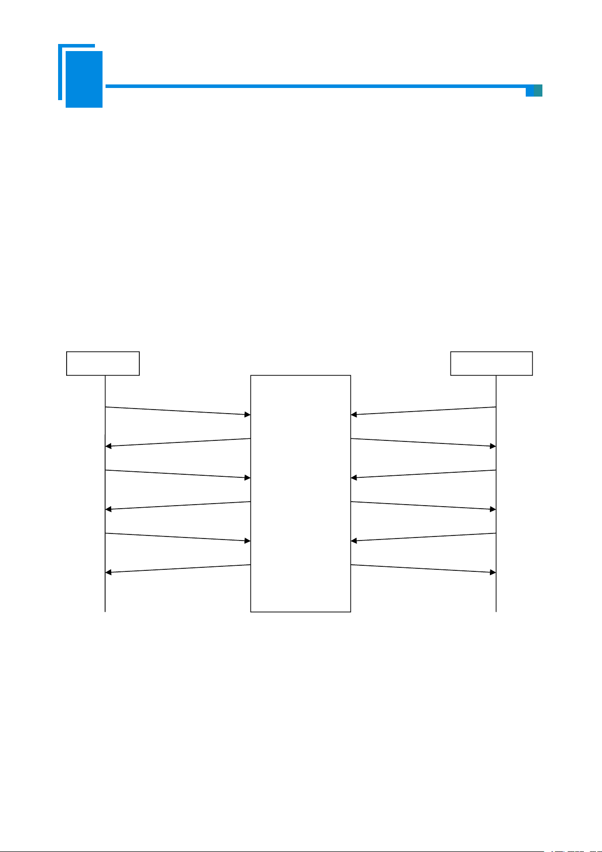
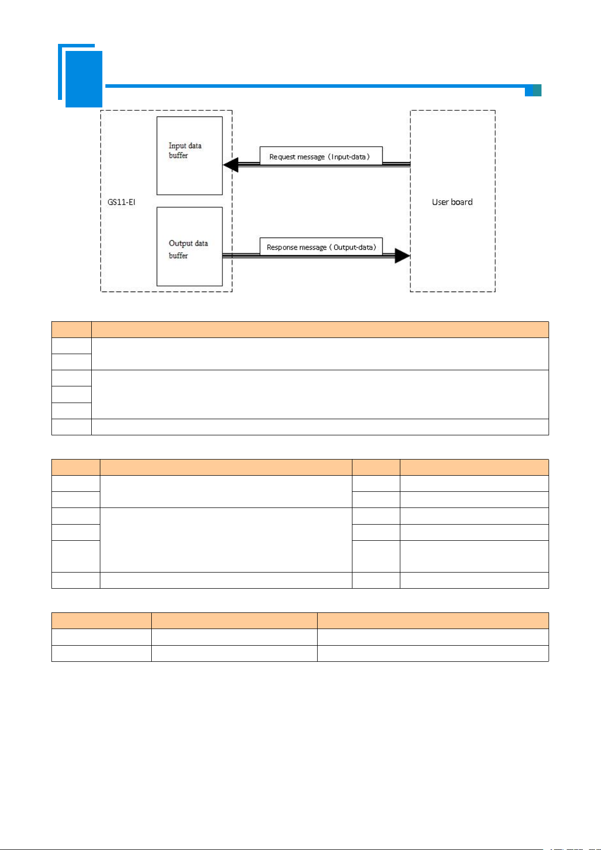
3.1 Description
GS11-EI acts as an EtherNet/IP server at the Ethernet side, serial port use user-defind protocol. The EtherNet
/ IP communication and serial communication are completely independent, through the internal input and output
data buffer of GS11-EI to realize data exchange, according to the GS11-EI serial communication protocol, the user
board can complete the input and output data exchange.
The procedure of message transmission is as follows:
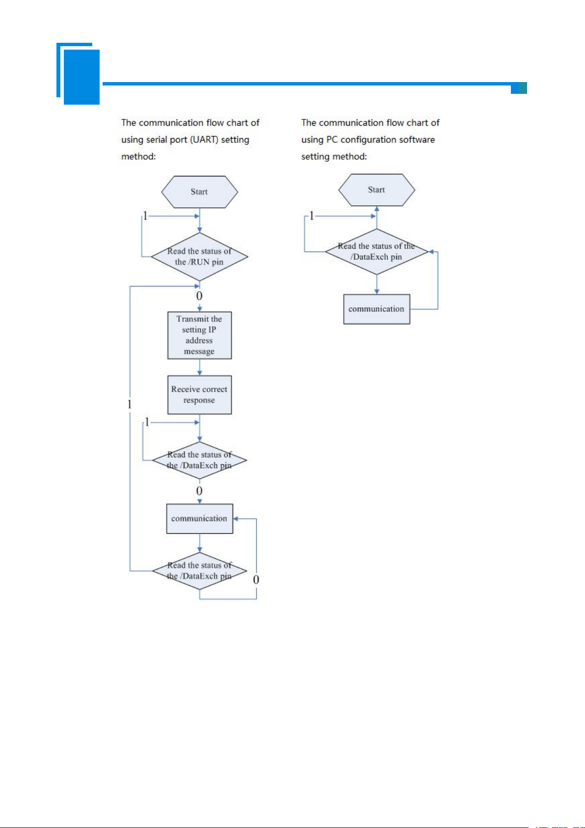
3.2 The GS11-EI Communication Flowchart and User Program
Here are the flowcharts of two kinds of IP configuration; users can choose one of them in accordance with
specific conditions. For the chooses of this two kinds, see also the Advanced Parameters section in chapter 6.4.
9
Page 11
User Manual
Embedded EtherNet/IP Module
GS11-EI
3.3 Real-time monitoring IP function
1. Using configuration software setting IP address mode: The module will obtain an IP again. User needs to
If the GS11-EI is set to DHCP, then the module will monitor its IP when it is running. If IP changed, it will
pull up /DataExch pin to logic 1.Then two cases:
read / DataExch pin state. If it re-becomes logic 0, indicating that the module has obtained IP, and the module
10
Page 12

User Manual
Embedded EtherNet/IP Module
GS11-EI
can begin to communicate;
2. Using UART setting IP address mode: GS11-EI will wait the user to send the setting IP address message, and
1. Initialize request message--- (user board->module), When you choose to use the serial port (UART) to set the
Byte
EtherNet/IP to user-defind protocol
0
message length is 17 which includes all following bytes except the check sum byte and the length
byte , high-byte first
1
2
The default value is 0; when user set GS11-EI via UART that use DHCP to assign IP address, the value
of this byte is 1 *
3
IP Configuration Mode, 0: Static Configuration; 1: DHCP ;
4
IP Address, high-byte first
5
6
7
8
Subnet Mask, high-byte first
9
10
11
12
Default Gateway Address, high-byte first
13
14
15
16
Reserved, always 0
17
Reserved, always 0
18
Reserved, always 0
19
Check sum, byte 0+byte 1+…+byte 18
the next step is the same with the first initialization.
3.4 Initialize Communication
Communication mode: user board (host) is the communication initiator, and GS11-EI responses.
Configuration of baud rate: GS11-EI reads these pins BAUD0, BAUD1 and BAUD2 that select the UART
baud rate when it power on or reset.
IP address and other information, you can sent this initialization request message.
Remarks:
when user set GS11-EI module via UART that use DHCP to assign IP address, user board sends above
message(the value of byte 2 should be 1)
11
Page 13
User Manual
Embedded EtherNet/IP Module
GS11-EI
And then, when GS11-EI does not receive the IP address that assigned by DHCP Server on the network, it
2. Initialize response message--- (module->user board)
byte
Correct Response
Incorrect Response
0
Data length is 2
Data length is 2
1
0:Correct
Error code (not 0)
2
0
Extra error code
3
Check sum, byte 0+byte 1+byte 2
Check sum, byte 0+byte 1+byte 2
3. Error code
Index
Error Code
Explanation
0
1
Check sum error.
1
2
Data length error.
23IP configuration mode does not exist.
4. Extra error code is always 0xFF
will send 0x2E to user board every 1second.
If and only if DHCP Server finished IP allocate, then GS11-EI will send a message that contained IP address,
subnet mask, and default gateway to user board.
For example: GS11-EI sends message to user board: 0C C0 A8 00 BB FF FF FF 00 C0 A8 00 01 95.
The 0x0C is the header and means there are 12 bytes behind, and followed by is a 4 bytes of IP address
(192.168.0.187), 4 bytes of subnet mask (255.255.255.0), 4 bytes The default gateway (192.168.0.1), the last byte
represents checksum.
when user set the GS11-EI module IP address via UART and does not use DHCP, user board sends above
message(the value of byte 2 should be 0), and then the module will send the following message to the user board.
3.5 User-defind Protocol
Communication mode: User board is the communication initiator, and GS11-EI responses.
The request messages contain input data, and the response messages contain output data. The communication
process is as follows:
12
Page 14
User Manual
Embedded EtherNet/IP Module
GS11-EI
1. Request message (user board -> module)
Byte
Description
0
message length includes all following bytes except the check sum byte , high-byte first
1
2
Input data, high-byte first
…
n
n+1
Check sum, byte 0+byte 1+…+byte n
2. Response message of user-defind protocol (module -> user board)
Byte
Correct response
Byte
Incorrect response
0
message length includes all following bytes except the
check sum byte , high-byte first
0
0x80
11Data length is2
2
Output data, high-byte first
2
Error code
…3Extra error code
n
4
Check sum, byte 0+byte 1+byte
2+byte3
n+1
Check sum, byte 0+byte 1+…+byte n
3. Error code
Index
Error code
Description
0
1
和校验错误
1
2
数据长度错误
4. Extra error code is always 0xFF.
13
Page 15
User Manual
Embedded EtherNet/IP Module
GS11-EI
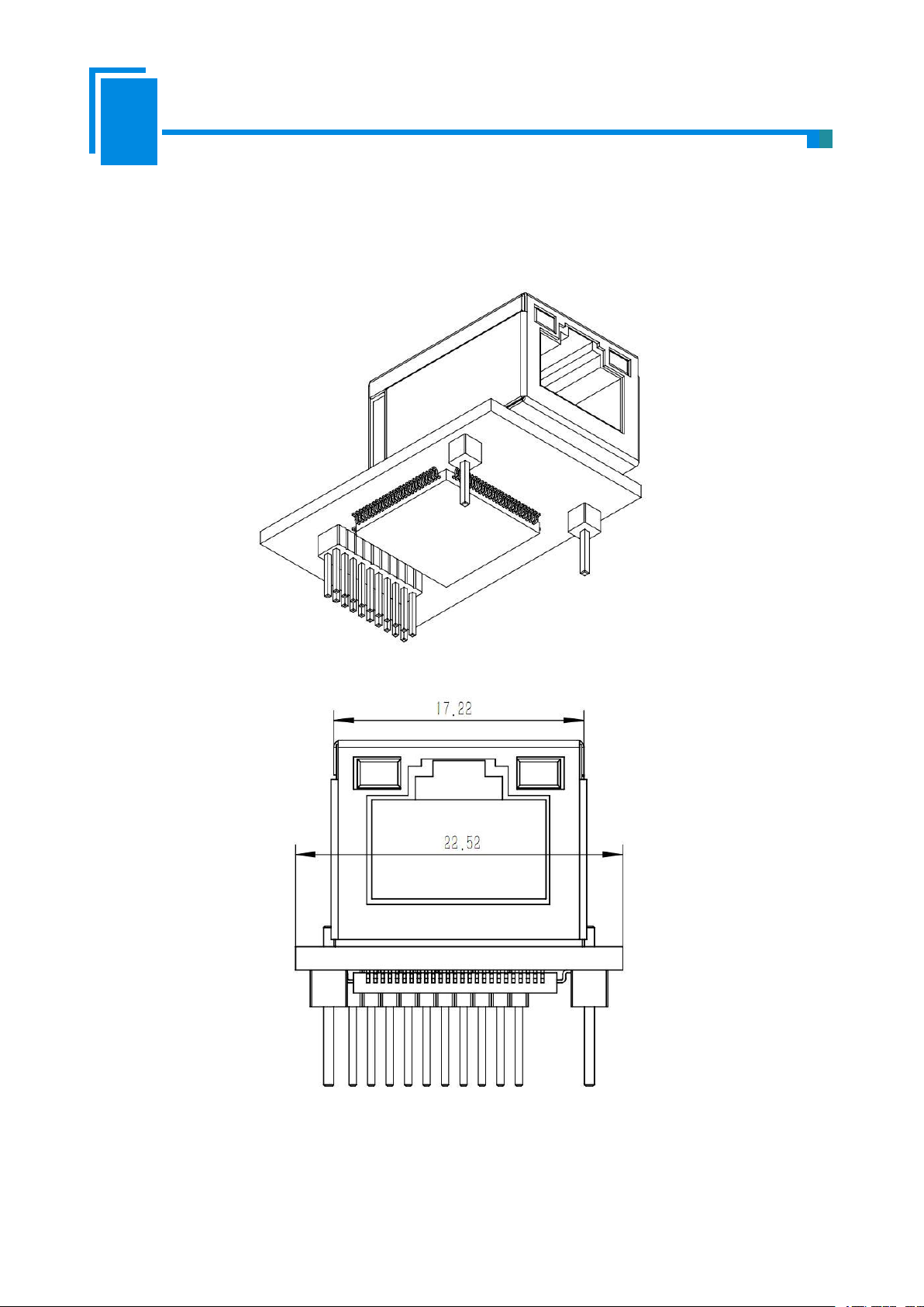
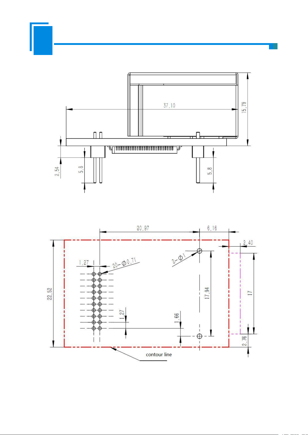
4. Dimension
Unit: [mm]
Front:
14
Page 16
User Manual
Embedded EtherNet/IP Module
GS11-EI
Side:
PCB dimension:
15
Page 17

User Manual
Embedded EtherNet/IP Module
GS11-EI
5. Development Board
Pin
Signal
Description
2
RX
Connect with pin TX of RS232 of PC
3
TX
Connect with pin RX of RS232 of PC
5
GND
Connect with pin GND of RS232 of PC
5.1 Appearance
5.2 Function
5.2.1 RS232 Interface
RS232 interface is DB9 pin-connector, the description show as follow:
DB9 hole-connector crossover cable must be used when connect the board with RS232 interface of PC, as shown
below:
16
Page 18

User Manual
Embedded EtherNet/IP Module
GS11-EI
RX
Development
board
TX
RS232 interface
RX
PC 机
TX
RS232 interface
GND
23523
5
5.2.2 Baudrate Setting Switch
1 2 3 4
ON
1
0
Low bit Middle bit High bit Default IP address
Index
High bit
Middle bit
Low bit
Corresponding baud rate(bps)
00002400
10014800
20109600
301119200
410038400
510157600
6110115200
7111230400
The 4-bit DIP switch on the development board is used to set the serial (UART) baud rate and default IP
address locking(For firmware update):
Corresponding relationship of baud rate is as follows:
The baud rate showing in the picture is 115200bps.
17
Page 19
User Manual
Embedded EtherNet/IP Module
GS11-EI
The fourth bit of DIP is “Default IP address locking” bit. When this bit is “ON”, Module is in firmware
Index
Name
Description
0
Power
Power indicator, On: Power on; Off: Power off
1
RTS
Reserve
2
TX
GS11-EI’UART transmits indicator;
Blinking: GS11-EI’UART is transmitting data;
Off: GS11-EI’UART isn't transmitting data.
3
RX
GS11-EI’UART receives indicator.
Blinking: GS11-EI’UART is receiving data;
Off: GS11-EI’UART isn't receiving data.
4
Run
GS11-EI status indicator,
On: In run status;
Off: In start-up status.
5
DataExch
GS11-EI data-interchange indicator,
On: In data-exchange status;
Off: Not in data-exchange status.
update state (unable to communicate normally), and the module will start up with default IP configuration.
IP address:192.168.0.11
Subnet mask:255.255.255.0
Default gateway:192.168.0.1
5.2.3 Reset Key
The key on the development board is the reset key, which is used to manual reset GS11-EI.
5.2.4 LED
There are six indicators on the development board, and the description is as follows:
18
Page 20

User Manual
Embedded EtherNet/IP Module
GS11-EI
6. Configuration Software
Put the product CD into the computer CD drive, open the CD, and install the configuration software
SST-EIP-CFG. Follow the prompts to complete the installation. Then open the configuration software and finish
the configuration of GS11-EI.
System Requirements:
· PC with 1 GHz processor or higher
· Windows® XP/Windows® 7
· Free disk space: min. 130 M Byte
· CD ROM drive
· RAM: min. 256 M Byte, recommended 512 M Byte
· Keyboard and Mouse
6.1 SST-EIP-CFG Introduction
SST-EIP-CFG is a product based on Windows platform, and is used to configure parameters of GS11-EI,
Double click the icon to run the SST-EIP-CFG and its main window will appear.:
19
Page 21

User Manual
Embedded EtherNet/IP Module
GS11-EI
6.2 Search Equipment
Before parameters configuration of GS11-EI, you need to search the equipment. Click the "Search
Equipment" button in the main window, SST-EIP-CFG will automatically list all of the GS11-EI on the network,
as shown below.
6.3 IP Search
When the user just wants to search a known IP address device on the network, click “IP Search” button in the
main window, and there will be popping up a dialog box: Fill in the IP address you want to search in the window
and click OK.
The SST-EIP-CFG will list the searched equipment in the table, as shown below.
20
Page 22

User Manual
Embedded EtherNet/IP Module
GS11-EI
6.4 Advanced Configuration
Note: The Advanced configuration is used to set your product-related parameters, here you need to set the
administrator password to prevent other users modify the Advanced parameters through the SST-EIP-CFG.
Select one device in the main window, Click “Advanced Configuration” button.
Pop out the following interface:
21
Page 23

User Manual
Embedded EtherNet/IP Module
GS11-EI
In this interface, users can configure: Ethernet, Password, IP Address Report and Advanced Parameters. The
Ethernet Parameters:(as shown above)
Name——Enter a name to identify the GS11-EI module, it can also be the name of user's final
IP Configuration Mode——Set the device's IP address configuration mode, Static or DHCP;
IP Address——Set the device's IP address;
Subnet Masks——Set the subnet mask of the device;
Default Gateway——Set the default gateway address of the device;
DNS1——currently not support
DNS2——currently not support
following describes the above interface in turn.
product;
22
Page 24

User Manual
Embedded EtherNet/IP Module
GS11-EI
Password(as shown below)
User Password: Refers to the password that you need to enter when you click the "advanced
configuration" button on the main screen. After the user password is set, you need to enter this
Admin Password: Refers to the password that you need to enter when you click the "advanced
IP Address Report:
password when configuring SST-EIP-CFG for user parameters. It is recommended not to set this
password. This password is for your users.
configuration" button on the main screen. After the admin password is set, you need to enter this
password when configuring SST-EIP-CFG for advanced parameters. It is recommended that the
user set this password after the product design is complete, in case your users modify the advanced
parameters.
It is used to set the GS11-EI to send a packet that reports its own current IP address, subnet mask, and default
gateway to a port of the specified IP address device, which is sent as UDP. You can enable this function by
23
Page 25

User Manual
Embedded EtherNet/IP Module
GS11-EI
clicking on the "IP Address Report" button in the main interface of SST-EIP-CFG. Click Start and the
SST-EIP-CFG will list all of the messages sent by the devices on the network.
After this function is enabled, you need to set the IP address and port number of the remote device, and the
auto report period, as shown below:
24
Page 26

User Manual
Embedded EtherNet/IP Module
GS11-EI
Advanced Parameters: (as shown above)
The way to obtain IP address
Setting the IP address via software SST-EIP-CFG: The PC configuration software refers to
Setting the IP address via host interface (UART): The user board sets the IP address and other
Ethernet/IP connection parameters: The GS11-EI supports 3 sets of connection parameters.
SST-EIP-CFG. Your users use this software to configure network parameters (user parameter
configuration).
parameters through the UART. The user board sets parameters such as the IP address by
sending an initialization request packet; see section 3.3.
Each set of parameters has input and output. The number of input and output bytes can be any
value from 0 to 256 bytes.
25
Page 27

User Manual
Embedded EtherNet/IP Module
GS11-EI
6.5 User Parameter Configuration
Note: The user parameter configuration is the parameters set by your user, such as the IP address parameters
(If the IP address obtain method in Advanced Parameters choose “Setting the IP address via software
SST-EIP-CFG”, see section 6.6)
In the main interface of the following figure, select the device need to be configured and click the
"Configuration" button.
Pop out the following interface:
26
Page 28

User Manual
Embedded EtherNet/IP Module
GS11-EI
In this interface, users can configure: Ethernet, Password, IP Address Report. The following describes the
Name——Enter a name to identify the GS11-EI module, it can also be the name of user's final
IP Configuration Mode——Set the device's IP address configuration mode, Static or DHCP;
IP Address——Set the device's IP address;
Subnet Masks——Set the subnet mask of the device;
Default Gateway——Set the default gateway address of the device;
DNS1——currently not support
DNS2——currently not support
above interface in turn.
Ethernet Parameters:(as shown above)
product;
27
Page 29

User Manual
Embedded EtherNet/IP Module
GS11-EI
Password:(as shown below)
User Password: Refers to the password that you need to enter when you click the "User parameter
IP Address Report:
configuration" button on the main screen. After the user password is set, you need to enter this
password when configuring SST-EIP-CFG for user parameters. It is recommended not to set this
password. This password is for your users.
It is used to set the GS11-EI to send a packet that reports its own current IP address, subnet mask, and default
gateway to a port of the specified IP address device, which is sent as UDP. You can enable this function by
clicking on the "IP Address Report" button in the main interface of SST-EIP-CFG. Click Start and the
SST-EIP-CFG will list all of the messages sent by the devices on the network.
28
Page 30

User Manual
Embedded EtherNet/IP Module
GS11-EI
After this function is enabled, you need to set the IP address and port number of the remote device, and the
auto report period, as shown below:
29
Page 31

User Manual
Embedded EtherNet/IP Module
GS11-EI
7. Configuration Software (EemTest)
7.1 Overview
EemTest is software based on Windows platforms, used to test embedded Ethernet module GS11-MT and
GS11-EI. The software function is to test the data transceiver of GS11-EI and GS11-MT. The manual introduces
the method of testing GS11-EI. You can obtain the method of testing GS11-MT in GS11-MT user manual.
You need to use the software with GS11-EI development board. We are very sorry that the testing software
may have bugs!
Double click the icon to enter the main Window:
7.2 User Interface
The main interface includes: Parameters Configuration section, Data Receiving section, Data Transmitting
section and some functional button.
Note: In the software, all the gray parts cannot be changed.
30
Page 32

User Manual
Embedded EtherNet/IP Module
GS11-EI
Work mode: The first combo box in Parameters Configuration session is to set work mode, the current
version of the GS11-EI only supports user-defind protocol operating mode.
Setting the IP address via host interface (UART): when you choose it, “IP configuration mode”, “IP
Input-data bytes, Output-data bytes: The value must be same with the max input and output data bytes of
Data Receiving section: To
display the data received.
Data Transmitting section: To
display the data need to be sent.
Parameters Configuration section: To
configure the parameters.
address”, “Subnet mask”, “Gateway address” can be changed. It is choose to set the IP address through
the serial port. See the Advanced Parameters in section 6.4.
EtherNet/IP set in the Advanced Parameters.
7.3 Establish/Disconnect Connection
Data in the Parameters Configuration section has default value, and you can input the value you need and
click “Run”. There will pop up a dialog box to configure serial port:
31
Page 33

User Manual
Embedded EtherNet/IP Module
GS11-EI
“Port” is the serial port being used; “Baudrate” is current serial port baud rate set by DIP switches.
After configuring parameters, click “Initialize” to establish the connection and initialize hardware
configuration.
When choosing “Setting the IP address via host interface (UART)”, click “Initialize” to send initial messages
and enter the running status.
If “Setting the IP address via host interface (UART)” is not chosen, click “Initialize” and enter the running
status directly.
If the connection is established successfully, all the options in the Parameters Configuration section will be
grayed, “Run” button will change to “Stop” and “Transmit” button will change to be usable.
32
Page 34

User Manual
Embedded EtherNet/IP Module
GS11-EI
If the connection is failed, there will pop up an alert dialog, and the options in the Parameters Configuration
section will not be grayed.
33
Page 35

User Manual
Embedded EtherNet/IP Module
GS11-EI
After establishing connection successfully, you can click "Stop" to disconnect the connection. The gray
options will be usable after disconnecting, “Stop” button will change to “Run”, and “Transmit” button will change
to be unusable.
7.4 Receive/Transmit Data
In the user-defind protocol operating mode, the test software is the initiator of the communication and the
module responds passively.
Transmit data: After establishing the connection successfully, you can click "Transmit" to transmit data
written in the data transmitting section. The format must be correct, and there is a space in each two bytes (HEX),
and the data length must be the same with “Input data bytes”.
Data receiving: After establishing the connection successfully, you will receive the data transmitted from the
module, and display the data in the data receiving section.
34
Page 36

User Manual
Embedded EtherNet/IP Module
GS11-EI
Cyclical: If you want to transmit data cyclically, you need to check “Cyclical”, and click “Transmit” button;
if you want to stop transmitting data cyclically, you only need to uncheck “Cyclical”.
Note: The format of the data transmitted must be correct, or you can not transmit them.
35
Page 37

User Manual
Embedded EtherNet/IP Module
GS11-EI
8. Precautions of Operation and Maintenance
The module must be protected from heavy pressure to prevent the panel damage;
The module must be protected from impact and may damage the internal components.
The supply voltage must be controlled within the requirements of the specification to prevent the
Water must be prevented from entering the module, which will affect normal work after water entering
Check the wiring before power on, whether there is a wrong connection or short circuit.
module from burning out;
the module.
36
Page 38

User Manual
Embedded EtherNet/IP Module
GS11-EI
Appendix: How to Read and Write I/O Data
There are 2 ways to read and write I/O data.
Use I/O Method to Read and Write Data
The following uses RSLogix 5000 as an example to explain how to use I/O method to read and write I/O
data.
Right-click on the EtherNet IP master module and choose "New Module..." as shown below:
37
Page 39

User Manual
Embedded EtherNet/IP Module
GS11-EI
In the pop out module selection window, click on the "+" in front of "Communications", select
"ETHERNET-MODULE" and click "OK" as shown below:
38
Page 40

User Manual
Embedded EtherNet/IP Module
GS11-EI
Set the related information of GS11-EI in the pop out window, as shown below.
Set the name of the added
EtherNet IP slave station
The IP address of GS11-EI
Set the Instance and the
corresponding number of bytes.
This setting indicates 128-byte
input, 128-byte output.
The module information that needs to be set in the above figure includes:
Name: Name the added EtherNet IP slave module (GS11-EI module)
Comm Format: Set the data type. User can choose to set the data type to DINT, INT, SINT, REAL, and so on.
39
Page 41

User Manual
Embedded EtherNet/IP Module
GS11-EI
This setting cannot be changed after confirmation. If you need to change the data type, you can create a new
module.
IP Address: Set the IP address of the EtherNet IP Slave module need to be connected, it is also the GS11-EI's
IP address.
Connection Parameters: Set the connection parameters used in the communication. For the connection
parameters supported by the GS11-EI, see the previous chapter.
Note: The size of "Size" set in the above figure (the number of bytes set) should be consistent with the
number of input and output bytes corresponding to the Instance described in the previous chapter.
Click "OK" to set the polling interval of the master station in the pop out interface. The default is 10ms, as
shown below:
After setting the master polling interval, click "OK" to save. Double-click "Controller Tags". In the pop out
window, click "GS11EI: O", as shown below:
40
Page 42

User Manual
Embedded EtherNet/IP Module
GS11-EI
In the figure above, GS11EI:O.Data [0]~GS11EI:O.Data [127] is the corresponding output data address of
the added GS11-EI module in the master station.
Click on "GS11EI: I", as shown below:
41
Page 43

User Manual
Embedded EtherNet/IP Module
GS11-EI
In the figure above, the 4 bytes corresponding to GS11EI:I.Data [0] is the real time frame header of EtherNet
IP slave station.
GS11EI: I.Data[1]~GS11EI: I.Data[127] is the corresponding input data address of the added GS11EI
module in the master station.
Use MSG Method to Read and Write Data
The following uses RSLogix 5000 as an example to explain how to use MSG to read and write I/O data.
Read I/O Data
Create a new project and be in "Offline" mode. Add two new tags "ReadTag" and "ReadData" under
"Controller Tags", and define the type of "ReadTag" as "MESSAGE" and define the type of "ReadData" as
"DINT[500]":
Right-click on "ReadTag" and select "Configure "ReadTag"":
42
Page 44

User Manual
Embedded EtherNet/IP Module
GS11-EI
In the new window that pops out, you need to make the following settings:
Message Type: CIP Generic
Service Type: select “Get Attribute Single”, at this point, the corresponding Service Code becomes to "e
(Hex)"
Class:4(Hex)
Instance:102(64Bytes)、112(128Bytes)、122(256Bytes)can be set
Attribute:3(Hex)
Destination: Select the "ReadData" tab. At this point, the read data will be saved in this tab.
43
Page 45

User Manual
Embedded EtherNet/IP Module
GS11-EI
Select the Communication tab. In the space after Path, enter the path which corresponding to the connected
EtherNet IP slave station. The format of the path is: the EtherNet IP master name, the slot number where the
EtherNet IP master resides, and the connected EtherNet IP address. After the path is set up, click "Apply" and
"Confirm". As shown below.
In this example, the name of EtherNet IP master is "Master", the EtherNet IP master station is in the slot
number "2", and the connected EtherNet IP slave (GS11-EI) has the IP address "192.168.0.10".
44
Page 46

User Manual
Embedded EtherNet/IP Module
GS11-EI
Add a "MSG" instruction to "MainRoutine" under "MainProgram" and select "ReadTag" as "Message
PLC read data instruction
Control", as shown below.
This is a simple instruction that can send a read request. In a normal program, some logical commands need
45
Page 47

User Manual
Embedded EtherNet/IP Module
GS11-EI
to be added to trigger this instruction. For details on this instruction, refer to RSLogix5000.
Download the program to the PLC and put the PLC in the "Online" state.
Click on "Control Tags" and select "Monitor Tags" to expand "ReadData", as shown below. The data stored
at the starting address ReadData[0] is the data of the Modbus slave station read by the PLC via the gateway
GS11-EI.
Write I/O Data
Go to the "Offline" mode, add two new tags "WriteTag" and "WriteData" under "Controller Tags", and define
the type of "WriteTag" as "MESSAGE" and the type of "WriteData" as "DINT[500 ]":
46
Page 48

User Manual
Embedded EtherNet/IP Module
GS11-EI
Go to the "Monitor Tags" page. WriteData[0] starts to input some data in the "WriteData" tab. The data will
be output by the PLC to the GS11-EI and output to the Modbus slave device via the configured Modbus write
command.
47
Page 49

User Manual
Embedded EtherNet/IP Module
GS11-EI
In the new window that pops out, you need to make the following settings:
Message Type: CIP Generic
Service Type: select “Get Attribute Single”, at this point, the corresponding Service Code becomes to
"10(Hex)"
Class:4(Hex)
Instance:101(64Bytes)、111(128Bytes)、121(256Bytes)can be set
Attribute:3(Hex)
Source Element: Select the "WriteData" tab. Represents use the data in the "WriteData" tab as PLC output
data.
Source Length: In bytes, this value should be less than or equal to the number of bytes represented by the
currently selected instance.
Destination: Select the "ReadData" tab. At this point, the read data will be saved in this tab.
48
Page 50

User Manual
Embedded EtherNet/IP Module
GS11-EI
Select the Communication tab. In the space after Path, enter the path which corresponding to the connected
EtherNet IP slave station. The format of the path is: the EtherNet IP master name, the slot number where the
EtherNet IP master resides, and the connected EtherNet IP address. After the path is set up, click "Apply" and
"Confirm". As shown below.
In this example, the EtherNet IP master station name is "Master", the EtherNet IP master station is in the slot
number "2", and the connected EtherNet IP slave (GS11-EI) has the IP address "192.168.0.10". The IP address of
49
Page 51

User Manual
Embedded EtherNet/IP Module
GS11-EI
the GS11-EI is downloaded to the module via software SST-EIP-CFG.
PLC write data instruction
PLC read data instruction
Add a "MSG" instruction to "MainRoutine" under "MainProgram" and select "WriteTag" as "Message
Control", as shown below.
Download the PLC program to the PLC and put the PLC in the "Online" state. The data in "WriteData" will
be output to the Modbus slave station via the GS11-EI (EtherNet IP Slave station).
50
 Loading...