

Page 1

TE
TETE
TE100
100100
100,,,,200
200200
200
I/P
I/PI/P
I/P CONVERTER
CONVERTERCONVERTER
CONVERTER
INSTRUCTION
INSTRUCTIONINSTRUCTION
INSTRUCTION MANUAL
MANUALMANUAL
MANUAL
(E)IM-TE100/00-R5
Page 2

Safety Precautions
Always read these instructions before using the I/P converter .
! WARNING:Indicates instructions that, if not followed correctly, “may lead to death
or serious injury”.
! Warnings
■ Install the flame-proof version in compliance with the “New Guidelines for Industrial
Electrical Equipment Explosion-Proofing 1979” issued by the Industrial Safety Institute of
the Ministry of Labor and in accordance with “technical procedures that comply with
international standards”.
■The flame-proof version and Intrinsically Safe version and Nonincendive may not be installed
or used for hazardous applications using gases other than those applicable to the
explosion-proofing grade of the I/P converter.
■ Perform adjustment (zero and span adjustment) of the flame-proof version in a
non-hazardous environment or after making the environment non-hazardous.
■Always turn off the power before removing the terminal box cover or main cover.
■If intending to remove or disassemble the pressure gauge for maintenance or other purposes,
always turn off the supply pressure and wait for the pressure in the pneumatic circuit to drop
to zero before undoing any screws or other fittings used to attach parts.
■Always turn off the supply pressure before switching between auto and manual or replacing
the pilot relay unit.
! CAUTION:Indicates instructions that, if not followed correctly, “may cause a fault
or other physical damage”.
! Cautions
■Fit the I/P converter in the orientation shown in section 3.2
■As drain fluid or dirt in the supply pressure line may block the fixed orifice or cause
misoperation, fit a 5[micro]m or finer air filter (such as an SSS Mini-Set filter) and use a
dryer or similar to ensure a clean air supply.
■Using a lubricator on the supply side may cause a blockage in the fixed orifice or nozzle.
Never use a lubricator with this I/Pconverter.
0-0
Page 3

- Table of Contents -
1.Usage 1-1
1-1 Check the I/P Converter Specifications 1-1
1-2 Transport 1-1
1-3 Storage Precautions 1-1
1-4 Install Location 1-1
2.Overview 2-1
2-1 Features 2-1
2-2 Principle of Operation 2-2
2-3 Specifications 2-3
2-4 Model Codes 2-3
2-5 Dimensions 2-4
2-6 Name of Parts 2-5
3.Design and Installation 3-1
3-1 Design 3-1
3-1-1 Flame-Proof Version 3-1
3-1-2 Intrinsically Safe Version 3-1
3-1-3 Nonincendive Version 3-1
3-2 Installation 3-2
3-2-1 Pipe Mounting 3-2
3-2-2 Wall Mounting 3-2
3-3 Pneumatic and Electrical Installation 3-2
3-3-1 Pneumatic Installation 3-2
3-3-2 Electrical Installation 3-3
(1)Flame-Proof Version 3-3,4
(2)Standard (Non-Explosion-proof)/Intrinsically Safe version 3-5
4.Operation 4-1
4-1 Auto/Manual Switchover Function(option) 4-1
4-2 Zero and Span Adjustment 4-2,3
4-3 Width of Range Adjustment 4-3
5.Maintenance 5-1
5-1 Maintenance of Flame -Proof Models 5-1
5-2 Periodic Inspection 5-1
5-3 Replacing the pilot Relay Unit 5-2
5-4 Replacement Parts 5-2
6.Troubleshooting 6-1
0-1
Page 4

1
Usage
1-1
Check the I/P converter Specifications
On receiving the I/P converter , check that the information on the nameplate on the front
of the I/P converter matches what you ordered and confirm that the model code is correct.
1-2
Transport
To prevent damage during transport, leave the I/P converter in its packing until ready to
install and use.
1-3
Storage Precautions
Store the I/P converter in a location that satisfies the following criteria.
●Not subject to rain or moisture
●Not subject to shock or other impact
●Normal room temperature and humidity
1-4
Install Location
To maintain the working life and performance of the transducer, observe the following
precautions when using the I/P converter.
(1) Ambient temperature
If using in a location subject to heat radiation or large variations in temperature, consider
fitting thermal insulation.
(2) Atmosphere
Try to select a well-ventilated location and avoid corrosive atmospheres.
1-1
Page 5

2
Overview
The TE100 and TE200 I/P converters convert an electrical signal (4 to 20mA DC) output
from a controller or similar to a pneumatic pressure. The I/P converters feature a compact
design and high accuracy, making them suitable for adjuster valve and similar
instrumentation applications.
2-1
Features
◆2-1 Features
Ultra light-weight, compact design at 1.6kg (1.8 kg with reducing valve fitted), the I/P
Converters are significantly lighter than previous models. This makes them easy to use.
◆High accuracy
The I/P Converters use a high-accuracy sensor and the latest technology to achieve a high
level of conversion accuracy.
◆Built-in reducing valve
A model is available that incorporates a small dedicated reducing value (Mini-Set XR100).
This eliminates the need for pneumatic supply piping.
◆Optimum mounting
Both pipe mounting and wall mounting are available by well designed bracket.
These enable the I/P Converters to be used in locations where space is limited.
◆100 and 200 series models are available
Both 100 series (with terminal box) and 200 series (no terminal box) models are available,
allowing you to select a model that best suits
2-1
Page 6
2-2
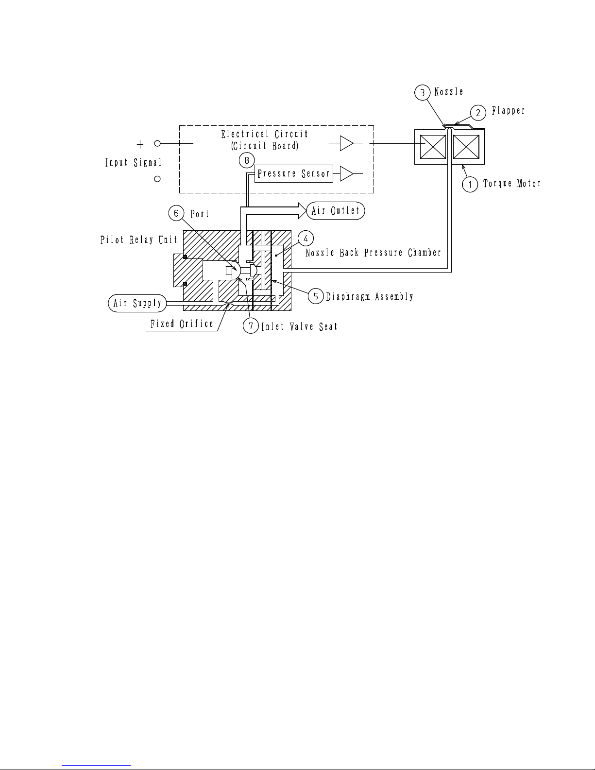
Principle of Operation
<
Transducer Operation Schematic
>
As shown in the above schematic, the operation of the I/P Converter is controlled by
applying a 4 to 20mA DC signal to the input which causes the internal circuit to generate a
voltage. A drive current is also supplied to the torque motor which represents the circuit
load to operate the overall system. If the level of the input signal increases, the current to
the torque motor [1] increases and the flapper [2] moves so as to cover the nozzle [3] and
raise the pressure in the pilot relay (pneumatic valve) nozzle back-pressure chamber [4].
The increased nozzle back-pressure causes a displacement in the diaphragm assembly [5]
in the pilot relay, opening the port’s [6] inlet valve seat [7]. This increases the output air
pressure from the pilot relay. The output air pressure is also applied to the solid state
sensor [8] and converted into an electrical signal proportional to the pressure. This
electrical signal is then returned to the control circuit where it is used as a feedback signal.
The control circuit compares the sensor signal against the input signal to control the output
air pressure to match the input signal.
2-2
Page 7

2-3
Specifications
Series
Parameter
TE100 (with terminal box)
TE200 (no terminal box)
Supply pressure
140kPa(1.4kgf/cm2)
Output pressure
20~100kPa(0.2~1kgf/cm2)
Input signal
4~20mADC
Accuracy
Accuracy ±5% Linearity ±0.2%, Hysteresis 0.2%, Repeatability 0.1%
Output air
approx. 40Nl/min
Air consumption
approx. 3Nl/min(4Nl/min approx. with Mini-set fitted)
Standard version (non-explosion-proof) : -20~80℃
S
Flame-proof:
Intrinsically safe (FM):
-20~60℃
Intrinsically safe (FM):-20~60℃
Standard version (non-explosion-proof) : -40~60℃
Ambient
temperature
L
Intrinsically safe (FM):-40~60℃
Air connection
Rc1/4(NPT1/4)
Electric
al
G1/2(NPT1/2)
Standard :dustproof and weather-proof (conforms to IP54, or JIS C0920-1993)
Intrinsically safe (FM):Class Ⅰ,Ⅱ,Ⅲ,Division 1,Groups A-G
Non-incendive(FM):Class Ⅰ,Ⅱ,Ⅲ,Divitsion2 Groups A,B,C,D,F,G
Temp.class:T4 NEMA 4X. Vmax=29V,Imax,96.1mA,Pmax=0.7W,Ci=0μF,Li=50μH
Housing
Flame-proof:ExdⅡBT6(TC13351)
―――
――――――
―――
Weight
approx.
1.6kg(1.8kg
with a Mini
-
set
approx. 1.3kg(1.5kg with a Mini-set integrated)
Material (Primary)
Aluminum Diecastings(Special Anodize)
2-4 Model Codes
1 2 3 4 5 6 7 8 9 10
TE □ □ □ - □ □ / □〇 □〇 □〇 □〇
TE:
I/P Converters models
2 3 4 5 6
Series Housing
Pneumatic and
Electrical
Connections
Ambient Temperature
AM
Function
1 100Series 0 Standard 1
Rc1/4・G1/2
Standard version
(non-explosion-proof)
-20~80℃
A NO
2 200series 2 Intrinsically safe 3
NPT1/4・G1/2
S
Flame proof &
Intrinsically safe ( FM)
-20~60℃
M YES
5 Flame- proof
5※
NPT1/4・NPT1/2
Standard
(non-explosion-proof)
-40~60℃
L
Intrinsically safe ( FM)
-40~60℃
7 8 9 10
Pressure Units Pressure Gauge Input Signal
Mini –set
Pneumatic Coupling
K2
200kPa G0 NONE M1
4~20mA
R1
Rc1/4
M2 0.2MPa G1 OUT-side only M2
4~12mA
N1
NPT1/4
P2 30psi M3
12~20mA
B2
2bar
G2
SUP-side
OUT-side
M4※
Special
Note :Contact SSS for details of items indicated by
※.
2-3
Page 8

2-5
Dimensions
<TE100>
<TE200>
<Bracket>
2-4
Fo r Ou tp ut
Page 9

2-6 Name of Each Part
<TE100>
<TE200>
2-5
Page 10

3
Design and Installation
3-1
Design
3-1-1 Flame proof
•
Do not use the I/P Converter in hazardous environments containing gases other
than those applicable to the explosion-proofing grade of the transducer.
•
Use the I/P Converter with the ambient temperature in the range -20 to 60[deg]C.
3-1-2 Intrinsically Safe version(Installation Diagram)
3-1-3 Nonincendive version(Installation Diagram)
3-1
Intrinsically safe
Hazardous( classified ) Location Non hazardous Location
Class Ⅰ,Ⅱ,Ⅲ
Division 1
Groups A,B,C,D,E,F,G
(Note 2)
Entity Parameters:
Vmax =29V Imax=96.1mA Pmax=0.7W
Ci=0μF Li=50μH
Note :
1. 7.53V<Voc<
Vmax, Isc or It<Imax, Ca>Ci+Ccable, La>Li+Lcable
2. Dust-tight conduit seal must be used when installed in ClassⅡand ClassⅢ environments.
3. Control equipment connected to the Associated Apparatus must not use or generate more than 250 Vrms or Vdc.
4. Installation should be in accordance with ANSI/ISA RP12.6 “Installation of Intrinsically Safe Systems for
Hazardous(Classified) Locations" and the National Electrical Code.
5. The configuration of associated apparatus must be FMRC Approved under Entity Concept.
6. Associated apparatus manufacturer’s installation drawing must be followed when installing this equipment.
7. No revision to drawing without prior FMRC approval.
+
-
( Note 5)
( Note 6
)
Control
Equipment
(Note 3)
Associated
Apparatus
TE100 or TE200
Nonincendive
Hazardous( classified ) Location Unclassified Location
Class Ⅰ,Ⅱ,Ⅲ
Division 2
Groups A,B,C,D,F,G
(Note 2)
Nonincendive Field Wiring Parameters:
Vmax =29V Pmax=0.7W Ci=0μF Li=50μH
Functional Rtaings
These ratings do not supersede hazardous location values. Normal current =4-20 mA
Note :
1. Vmax>=Voc or Vt>=7.53V, Ca>=Ci+Ccable, La>=Li+Lcable
2. Control equipment connected to the TE model series must not use more than 250 Vrms or Vdc.
3. Installation shall be in accordance with the National Electrical Code ANSI/NFPA 70.
4. Dust-tight conduit seal must be used when installed in ClassⅡand ClassⅢ environments.
5. No revision to drawings without prior FM Approvals authorisation.
6. The nonincendive field wiring circuit allows interconnection of nonincendive field wiring apparatus with associated
nonincendive field wiring apparatus using any of the wiring methods permitted for unclassified locations.
7. For this current controlled circuit, the parameter(Imax)is not required and need not be aligned with parameter (Isc
of It)of the
barrier
or associated nonincendive field wiring apparatus.
+
-
Control
Equipment
(Note 2 )
TE100 or TE200
Page 11

3-2
Installation
3-2-1
Pipe Mounting
3-2-2
Wall-Mounting
3-3
Pneumatic and Electrical Installation
3-3-1
Pneumatic Installation
The I/P Converter requires a clean and dry air supply. Provide a system able to deliver
such an air supply.
①
The I/P Converter can be ordered with either Rc1/4 or NPT1/4 couplings. Ensure you
use the correct couplings to match those on I/P Converter.
②
Connect the piping using the appropriate procedure depending upon whether a
reducing valve (Mini-Set XR100) is fitted or not.
If a reducing valve is not fitted, connect to the SUPPLY inlet on the I/P Converter.
If a reducing valve (Mini-Set XR100) is fitted, connect to the “P1” coupling on the
Mini-Set unit.
③
Ensure you fully purge the piping before connection to prevent any particles of dirt or
foreign material from entering the system.
④
Adjust the supply pressure to deliver a 140kPa (1.4kgf/cm[2]) air supply. If using a
Mini-Set, turn the adjustment knob on the Mini-Set to set the pressure to 140kPa
(1.4kgf/cm[2]).
3-2
Page 12

3-3-2
Electrical Installation
(1)
Flame-proof version
When performing electrical installation, never remove the terminal box cover or
attempt to connect the wiring while the electrical power is still connected. (Similarly,
do not open the main cover.)
①
Cabling
Use insulated cables able to withstand temperatures of 75[deg]C or higher for the
external cabling.
②
External conductor cabling
The following two methods can be used for conductor cabling on the Flame-proof
version (Exd II BT6).
Cable pipe with threaded pressure coupling method
Use a G1/2 thick steel cable pipe (PF1/2 equivalent) with a lock nut to provide a
full threaded coupling. Alternatively, use a sealing fitting.
Pressure-proof packing method
Use a cable gland.
(The table below lists the applicable cable diameters.)
(Cable glands with the part numbers listed below are available as optional extras.
Please specify when ordering.)
Model Standard Rating Number
Applicable Cable
Diameters
Cable Gland Part No.
TE15● ExdⅡBT6
TC13351
φ8~φ10
φ9~φ11
φ10~φ12
KHB-0-16/PK1610
KHB-0-16/PK1611
KHB-0-16/PK1612
3-3
Page 13

③
Connecting the cables
To connect the cables, remove the terminal box cover and use the insulated
crimping terminals on the terminal block.
Connect by crimping the + input terminal to the + terminal (red) and the - input
terminal to the - terminal (blue). (See Figure 3-1)
* To remove the cover, undo the locking screws (hex set screws)
Figure 3-1
④
Locking
After partially attaching the terminal box cover, lock the cover in place using the
locking screw.
⑤
Other details
All other aspects of the installation should be carried out in compliance with the
“New Guidelines for Industrial Electrical Equipment Explosion-Proofing 1979”
issued by the Industrial Safety Institute of the Ministry of Labor and in
accordance with “technical procedures that comply with international standards”.
3-4
Page 14

(2)
Standard (non-explosion-proof) / Intrinsically Safe version
①
Cabling
If the ambient temperature is 60[deg]C or less, use 600V vinyl or better stranded
cable.
(If the temperature is above 60[deg]C, select cable with an appropriate tolerance for
the conditions.)
②
Connecting the cables
•
TE100 (with terminal box)
To connect the cables, remove the terminal box cover and use the insulated
crimping terminals on the terminal block.
Connect by crimping the + input terminal to the + terminal (red) and the -
input terminal to the - terminal (blue). (See Figure 3-1)
•
TE200 (no terminal box)
Remove the main cover and connect to the terminal block on the circuit board
as described above.
The terminal polarities are indicated on the protective plate.
(See Figure 3-2)
Figure 3-2
3-5
4
Operation
Page 15

4-1
Auto/Manual Switchover Function (Option)
The I/P Converter is shipped set to automatic operation.
To operate the transducer manually, use the following procedure to switch to manual
operation. (See Figure 4-1)
(The auto/manual switch is located on the left side of the I/P Converter unit.)
Auto/Manual Switch
Figure 4-1
<Changing to MANUAL>
[1] Undo the screw and slide the protective plate so that the “M” becomes visible. Partially
retighten the screw in this position.
[2] Next, use a screwdriver to rotate the AM switch shaft as far as it will go in the direction
of the arrow on the plate (MANU direction).
[3] Adjust the reducing valve used to control the air supply to set the I/P Converter output
pressure. The output pressure is indicated on the output pressure gauge.
<Restoring to AUTO>
[1] To set back to AUTO, rotate the AM switch shaft as far as it will go in the AUTO
direction.
[2] Slide the protective plate so that the “A” becomes visible again, then fasten in place.
4-1
4-2
Zero and Span Adjustment
(1) Set the AM switch function to AUTO and set the supply pressure to 140kPa
Page 16

(1.4kgf/cm[2]).
(2) Remove the main cover.
On the Flame-proof version, the main cover cannot be removed while the power
is on. Move to a non-hazardous location before removing the main cover.
(3) Zero and span adjustment
(a) Apply a 0% (4mA) input signal
Rotate the zero trimmer to set the 0% output (20kPa, 0.2kgf/cm[2]). Rotating
clockwise increases the output and rotating counter-clockwise reduces the output.
(See Figure 4-2)
(b)
Next, apply a 100% (20mA) input signal
Rotate the span adjustment trimmer to set the 100% output (100kPa, 1.0kgf/cm[2]).
Rotating clockwise increases the span and rotating counter-clockwise reduces the
span.
(See Figure 4-2)
(c)
Repeat the above adjustments two or three times to set the zero and span settings.
(d)
After you have finished setting the zero and span adjustment, apply a step input
(25%, for example) and check that the output is correct.
<Figure 4-2>
4-2
(4)
1/2 split-range version
The I/O specifications for the 1/2 split range version are listed below.
Adjust the zero and span settings using the same procedure as for the standard range
Page 17

version.
Range 0% 100%
4~12mA
4mA 12mA
12~20mA
12mA 20mA
4-3
Width of Range Adjustment
The table below shows the width of the zero and span adjustment bands.
You can set the range to be different to the standard 0 to 100% output provided you stay
within these limits.
Zero adjustment width
-10%~+10%
Span adjustment width
+75%~+125%
4-3
5
Maintenance
5-1
Maintenance of Flame-Proof version.
Page 18

1.When performing maintenance on Flame-proof version, never remove the terminal
box cover or main cover while the power is connected.
2.
Always turn off the power before performing any maintenance or repair work.
5-2
Periodic Inspection
Performing periodic inspection and maintenance of the I/P Converter will help reduce the
incidence of faults and extend the working life of the unit.
<Supply pressure filter>
・A metal mesh is fitted inside the SUPPLY coupling. Use a pair of tweezers or similar to
remove any sealing tape or dirt particles caught in the mesh.
<Fixed orifice assembly>
・The fixed orifice plays an important role in supplying the air to the nozzle. If no nozzle
back pressure is present, this may indicate a blocked orifice.
・Take off the exhaust cover, then remove the fixed orifice assembly from the pilot relay
unit and replace with a spare assembly. (See Figure 5-1)
・If you do not have a spare fixed orifice assembly, use [phi]0.3 piano wire or similar to
clean the blocked orifice. Then use clean air to blow off any remaining dirt.
・When finished cleaning, screw the assembly back into its original position. Take care to
ensure that the O-ring is positioned correctly in the body of the pilot relay unit.
図 5-1
5-1
5-3
Replacing the Pilot Relay
To remove the pilot relay unit, remove the exhaust cover from the bottom of the I/P
Converter and undo the two screws. (See Figure 5-2)
Page 19

figure 5-2
* When replacing the pilot relay unit, insert the new relay unit.
5-4
Replacement Parts
Name
Part No.
Quantity
TE100: TE100-500-11A
Circuit board
TE200: TE100-500-11B
1
Pilot relay unit
TE100-200 1
Filter for reducing valve
XR100-109 1
5-2
6
Troubleshooting
Refer to the table below in the event of problems with the I/P Converter .
If the action described below does not restore the transducer to normal operation, replace
the I/P Converter with a spare and contact SSS Co. Ltd.
Page 20

Symptom Cause Action
Fixed orifice is blocked.
Clean or replace fixed
orifice.
I/P Converter
is set to manual
operation.
Change to Auto (A)
operation.
Polarity of input signal wiring is
reversed.
Check wiring and
connections.
No air supply
Supply 140kPa
(1.4kgf/cm[2])
I/P Converter
does not operate
when an input
signal is applied.
Pilot relay is faulty.
Inspect and/or replace pilot
relay.
Large fluctuation in air supply
pressure
Ensure air supply pressure
is constant.
The pressure leakage (volume) on
the output circuit side is fluctuating.
Check for pressure leaks.
Output is
unstable.
Pilot relay is faulty.
Inspect and/or replace pilot
relay.
Zero and span settings are out of
adjustment.
Re-adjust
zero and span
settings.
Large fluctuation in ambient
temperature
Fit thermal insulation or
similar.
Large output
error
Pressure leak in output circuit Fix pressure leak.
6-1
 Loading...