

Page 1

System Manual Access
Issue 2013
Page 2

2
Contents
System description Safety
remarks 3
System structure, conductor
material and range
Door area 4
Network LAN 5
Cabling for indoor devices 6
System components
Overview
7
Door area 8-11
Indoor devices 12-13
Distribution 14-15
Software 16-17
Licences 18
External devices 19
Installation
AS-AV Siedle Vario 20-21
AS-AV Siedle Classic 22-23
AS-AV Siedle Steel 24-25
AS-AV Siedle Vario with
supplementary supply 26-27
AS-AV Siedle Vario with
pilfer safeguard DSC602-0 28-29
AS-AV Siedle Vario with
external camera 30-31
AS-AV with Access custom-
t door loudspeaker and
external camera 32-33
AS-AV with Access custom-t
door loudspeaker and Access
camera module 34-35
AS-AV Siedle Vario with
DRM 611-... 36-37
AS-AV Siedle Vario with
COM 611-... 38-39
AS-AV external camera with
video distributor 40-41
AS-AV external camera 42-43
AS-AA Siedle Vario 44-45
AS-AA with Access customt door loudspeaker 46-47
Storey call button, customer‘s
own signalling device 48-49
Information on
programming 50
Initial commissioning/Login 51
Servicing 52-53
LED displays 54-55
Glossary 56
Index 57
Page 3
3
Siedle Access is a powerful communication system based on
groundbreaking IP technology.
Communication is enabled both
for audio and video and also for
switching, control and signalling.
The ideal eld of application for the
system is either in large properties
or in any type of facility entailing
complex technical requirements. Due
to the central administration of the
entire system, the work involved in
commissioning and maintenance is
kept to a minimum. The installation
is based on network technology,
making it extremely open for further
expansion.
Commercial and private applications
can be mixed or combined at will.
Technology parks can be connected
to administration or training centres
under a single cohesive system, even
across different buildings, while still
retaining their own independent
functions.
Generally speaking, a distinction is
drawn between the door area and
the protected local area network
(LAN). A detailed description of
these two areas is provided in the
section System structure/conductor
material.
Electrical voltage
Mounting, installation and servicing
work on electrical devices may only
be performed by a suitably qualied
electrician. Failure to observe this
regulation could result in the risk of
serious damage to health or fatal
injury due to electric shocks.
Electrostatic charging
As a result of electrostatic charging,
direct contact with the circuit board
can result in destruction of the
device. Direct contact with the circuit
board must therefore be avoided.
• When working at the device,
observe the remarks relating to
mains cut-off.
• Observe the DIN EN 60065
standard! When establishing the
electronic connection, observe the
requirements of VDE 0805 or EN
60950.
• The building installation must
include an all-pole mains switch
with a contact separation of at least
3mm.
• Ensure maximum fusing of 16A for
the mains connection in the building
installation.
• When planning large-scale
(complex) systems, the distributor
space required for the switch panel
mounting devices must be taken
into consideration in the distributor
planning process.No external voltages >30 V AC/DC may be applied
to system users.
Devices with 230 V connection
In accordance with DIN VDE 0100
part 410, section 411.1.3 attention
must be paid to ensuring a safe
separation between system lines and
the mains voltage; i.e. system and
mains cores must not be permitted
to touch! The system line cable
(extra-low safety voltage) must be
stripped back by the minimum possible.
During the update process, the
power supply to the devices must
not be interrupted, as this can result
in damage. In this case, a repeat
update is no longer possible, and the
devices will have to be sent in for
repair.
System description
Safety remarks
Page 4
4
System structure, conductor material and range
Door area
Generally speaking, a distinction is
drawn between the door area and
the protected local area network
(LAN).
Door area
The installation for the door station
is referred to as the door area. If correctly installed, this area is protected
from unauthorized access. From the
outside, it is not possible to access
the network.
Cabling in the door area
The IP network terminates with the
ATLC/NG 670-...
To protect against unauthorized
access, the ATLC/NG 670-... must be
accommodated without fail inside
the building.
The cabling from the ATLC/
NG 670-... to the door station is
executed in the conventional way.
Conductor material
CAT AWG22
J-Y(ST)Y twisted pair conductors,
shielded
Range
Door controller to door station
CAT AWG22 = 120 m
J-Y(St)Y ø 0,6 mm = 100 m
J-Y(St)Y ø 0,8 mm = 200 m
Every door station/independent
camera is installed in the system
with its own ATLC/NG670-...
If an external camera is directly
supplied, the distance between
the AIVS670-... and camera may
increase to >10m. This range is
dependent on the output signal of
the camera and the quality of the
coaxial cable used. The AIVS670-...
requires a video input signal of
1Vss.
Tö
ATLC/NG 670 ATLC/NG 670
max. 10 m
Door station
Camera
Door area
Network LAN
Range depends on the
installed conductor material.
Network LAN
Page 5
5
System structure, conductor material and range
Network LAN
Network LAN
The requirement for integration of
an Access system is a network infrastructure created in accordance with
the stipulations for generic cabling
(from Category5).
Rules for generic cabling are set out
in various standards:
• DIN 50173-1 General requirements
For individual building types, the following standards apply in addition:
• DIN 50173-2 (ISO/IEC 11801) for
ofce buildings
• DIN 50173-3 (ISO/IEC 24702) for
industrially used locations
• DIN 50173-4 (ISO/IEC 15018) for
apartments
Internationally, the ISO/IEC standards
apply.
Cabling structure/areas
The cabling is broken down into 3
areas.
Primary area
• Fibre optic cables
• Cabling between individual
buildings and/or within buildings
between several main building distributors.
• In the case of copper wire connections, adequate equipotential
bonding must be guaranteed.
Secondary area
• Fibre optic cables
• The storeys are networked by
means of storey distributors. Both
bre optic and copper connections
can be used. This is dependent upon
the switches used and their distance
from the main distributor/switch.
Tertiary area
• Twisted pair for xed installation
plus patch cable for cabling from
the network junction box to the
terminal.
ATLC/NG 670
Tö
Server
Switch
Door station
Primary area
Tertiary area
Secondary area
Page 6
6
System structure, conductor material and range
Cabling for indoor devices
Cabling for indoor devices
The Access indoor devices can be
installed without problems using
standard RJ45 ush mounting network junction boxes.
In this case, simply install the network junction box without the frame
and panel. The Siedle indoor device
can be mounted above the junction
box and connected to the network
with a plug-in connector.
If there is no ush mounted network
socket at the required mounting
height due to circumstances on site,
the indoor call station can be surface
mounted with the AZA870-... In
this case, the connection from the
indoor call station to the network is
established using a patch cable (not
provided).
If the indoor call station is intended
for use as a table-top unit, the
device can be converted using the
AZTV 870-... with 3 metre long connecting cable.
An indoor device may only be connected to the network using an
RJ458/8(8) network socket.
165 cm
Eye level
Junction box
RJ45
150 cm
165 cm
Eye level
Junction box
RJ45
Page 7
7
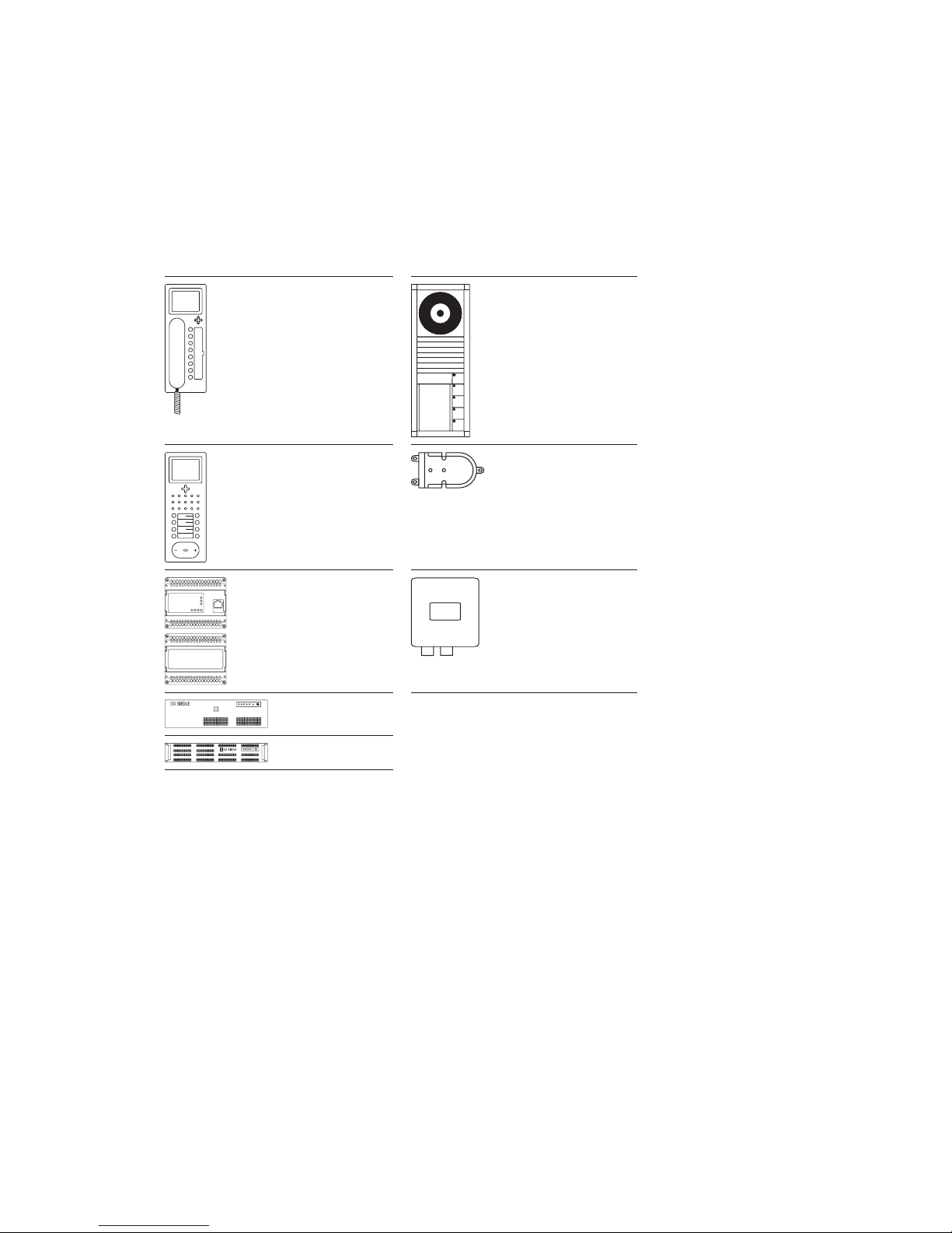
System components
Overview
Devices integrated in the LAN network (protected area) are linked by
an interface to the door.
Devices assigned to the door area.
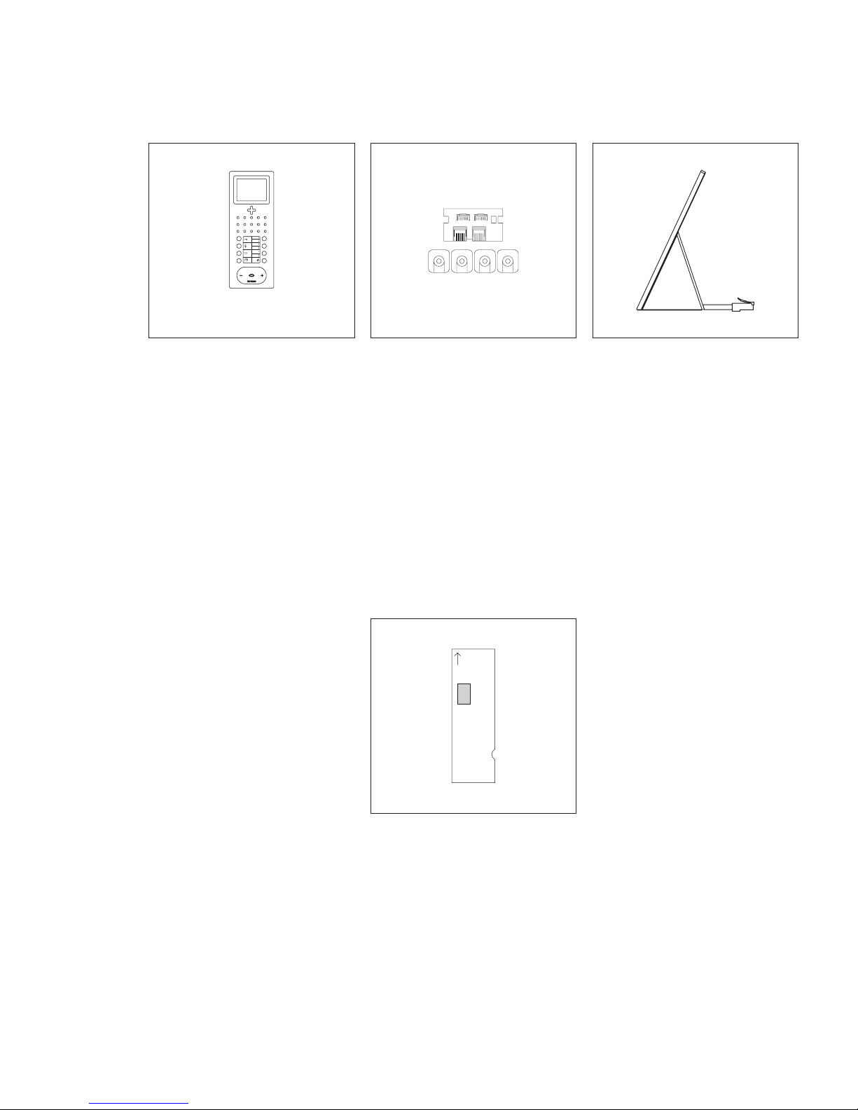
AHT 870-...
AHTV 870-...
ATLM 670-...,
ACM 670-...,
AHF 870-...
AHFV 870-...
ATLE 670-...,
ATLC/NG 670-... AIVS 670-...
AS 670-... S
AS 670-... M, L
Page 8

8
System components
Door area
ATLM 670-0
Access door loudspeaker module in
611 Vario design.
Complete module with loudspeaker,
microphone and light button with
LED illuminated light symbol.
Up to max. 48 call button modules
can be connected in any optional
combination, allowing up to max.
192 users.
Acoustic feedback when actuating
the call button at the BTM 650-01 to
-04 optional.
BTM 650-01 to 04
Bus call button modules BTM 650-...
with 1, 2, 3 or 4 call buttons. The
BTM 650-... is connected to the
ATLM 670-... via ribbon cable.
COM 611-02
Code lock module as an input device
for the placement of door calls and
control functions in conjunction with
Access and the Siedle access control
system.
• With keypad for making calls or
• For controlling in conjunction with
the Easikey controller EC602...
• C button for cancelling incorrect
inputs
• DR button for direct door release
via the EC602-...
DRM 611-01
Display call module as an input
device with 4-line display for placing
door calls.
Indication of names in the display in
alphabetical order.
The DRM611-... can also be used in
combination with the COM611-...
in order to display the input via the
COM611-...
The PRI602-...USB and the
ZWA640 are required for program-
ming.
Page 9
9
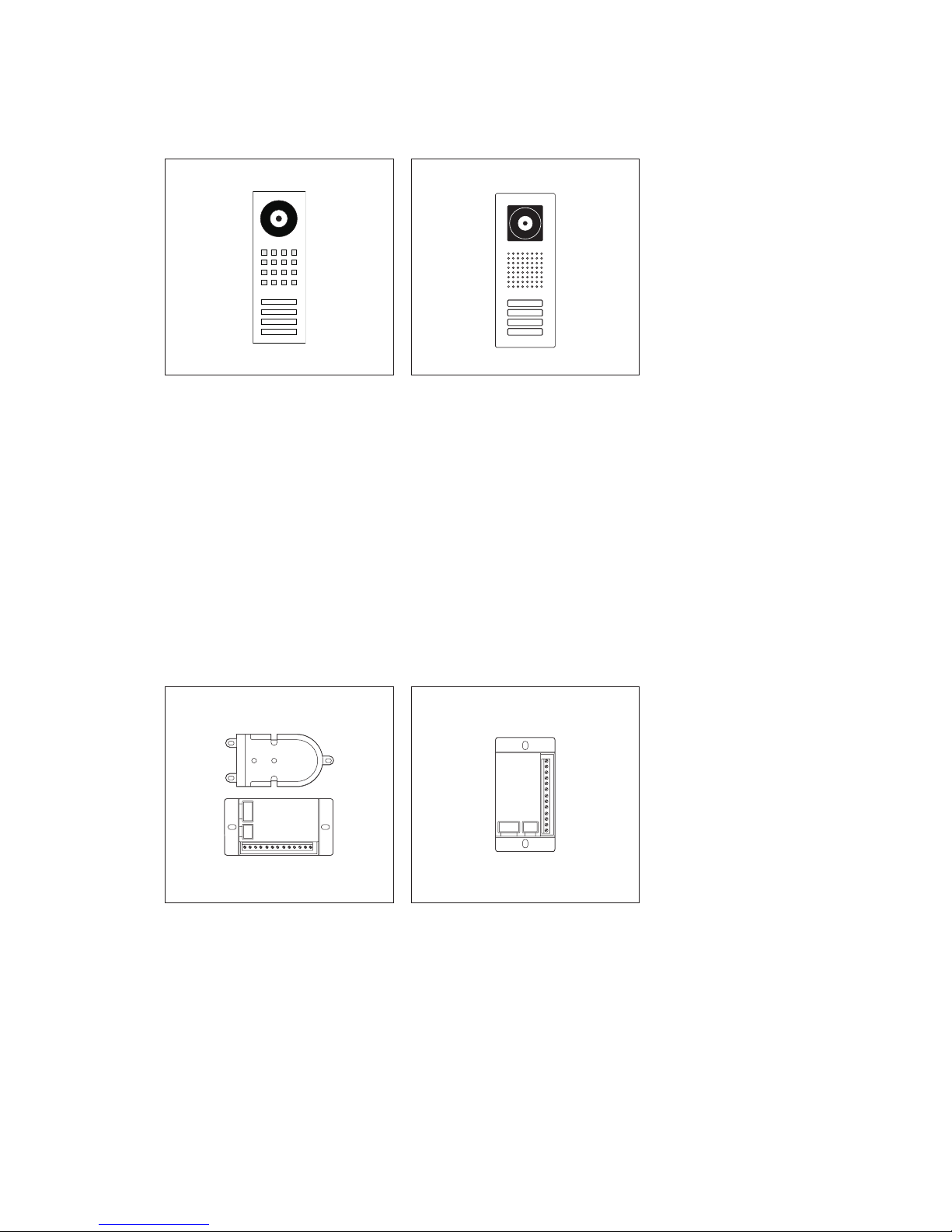
Siedle Steel STL...
Door station in the Steel design
line, with stainless steel front,
door loudspeaker, call buttons and
Access camera. LED-illuminated bell
buttons, 3 mA, 12VAC each per
button.
ATLE 670-0
Access custom-t door loudspeaker
with bus call button matrix for
mounting in a loudspeaker compartment, door constructions, letterboxes etc.
12of the client’s own call buttons
can be directly connected at the bus
call button matrix BRMA050-...
Control output for external camera,
connection of existing buttons via
BRMA 050-...
BRMA 050-01
Bus call button matrix for the connection of existing call buttons to
the custom-t door loudspeaker
BTLE050-.../ATLE670-...
Max. 14 BRMA 050-... can be connected to 1 BTLE 050-...
Max. 16 BRMA 050-... can be connected to 1 ATLE 670-...
Siedle Classic
Door station in the Classic design
line, with stainless steel front,
door loudspeaker, call buttons and
Access camera. LED-illuminated bell
buttons, 5 mA, 12VAC each per
button.
Page 10
10
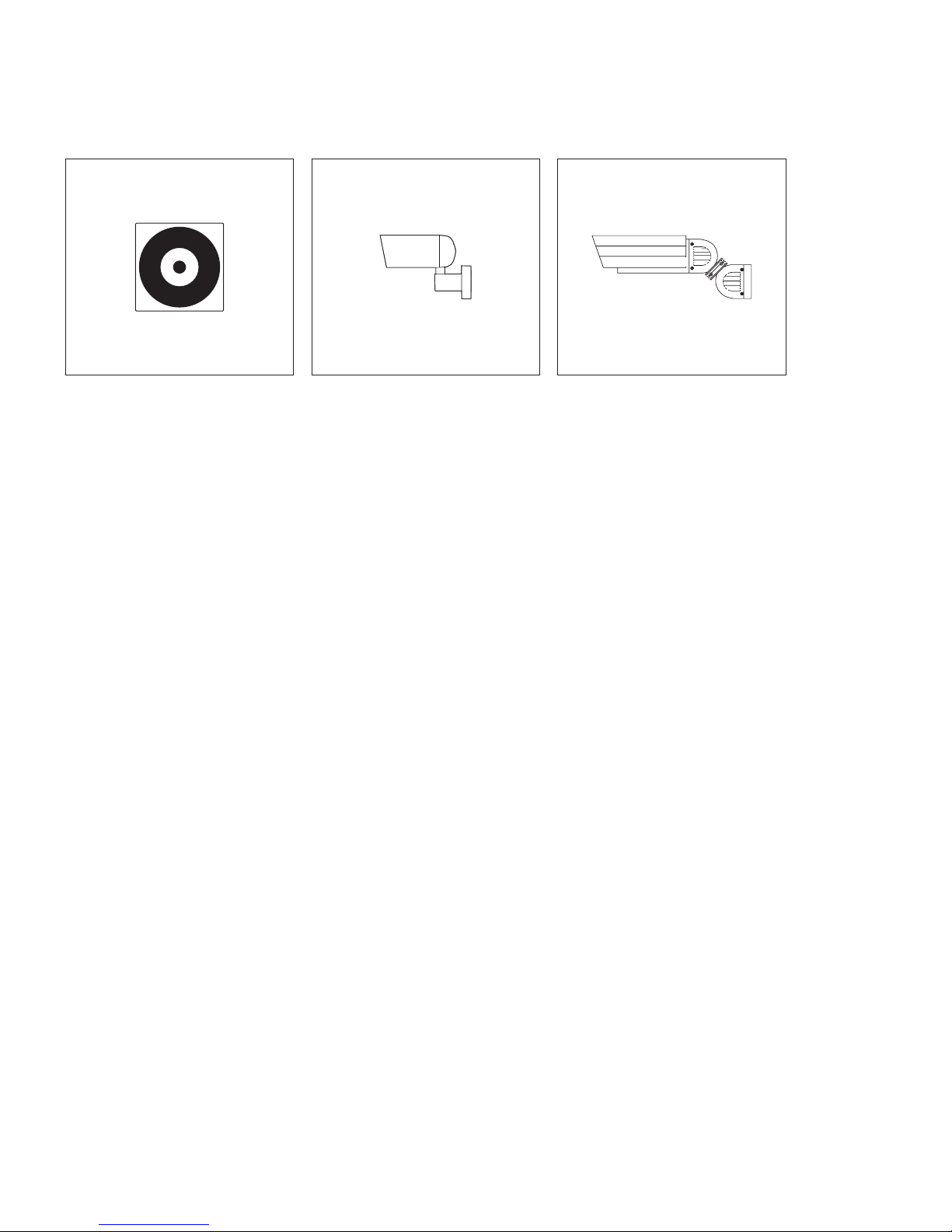
CEC 612-0
Day/night CCD video camera for
external mounting, in weather-proof
housing and wall arm with ball
head, internal cable routing.
• Image pick-up colour CCD sensor
8.4 mm (1/3“); 752 (H) x 582 (V)
440.000 pixel
• Zoom-lens attachment
3.8–9.5 mm, F 1,2, with IR lter,
automatic swivel action
• Pick-up angle 74°–30°
• Light sensitivity 0.5 Lux in colour
mode and 0.24 Lux in monochrome
mode, each at F 1.2
• Backlight compensation
• Automatic white balance
• Resolution horizontal 480 TV lines
• Video signal 1 Vpp, FBAS, at
75 Ohm
KA/WG 950-0 C
Day/night CCD video camera for
external mounting, with weatherproof housing and sun shade, wall
arm with ball head and internal
wiring.
• Image pick-up colour CCD sensor
6.3 mm (1/4“); 752 (H) x 582 (V)
400,000 pixel
• Lens attachment 3.9–85.9 mm
without IR lter
• Pick-up angle 50°–2.5°
• Light sensitivity 0.8 Lux at F 1,2
• Resolution horizontal 480 TV lines
• Video signal 1 Vpp at 75 Ohm
• Connecting cable in wall arm
ZNF 950-0
Line rectier foot accessory for the
camera KA/WG 950-..., for supplying from the 230 V network.
The cameras are connected by plugin connections.
ACM 670-0
Access camera module for mounting
in Siedle Vario 611-housing.
Performance features:
• Integrated heating with 2-stage
temperature control
• Infrared lighting and control electronics
• Colour system PAL
• Image pick-up CCD sensor 8.4 mm
(1/3”) 752 x 582 pixel (horizontal/
vertical)
• Lens attachment 2.9 mm
• Automatic day/night switchover at
approx. 4 lux (from colour to monochrome) for optimized quality
• Pick-up angle vertical 60°,
horizontal 80°
• Additional mechanical adjustment
range 30° horizontal and vertical
• Horizontal resolution 450 lines
System components
Door area
Page 11

11
The connection of analogue cameras
generally takes place via the Access
interface analogue-video standard
AIVS 670-...
AIVS 670
Access Interface
Analog-Video Standard
AIVS 670-0
Access analog video standard interface in surface-mount housing for
connection of an analog camera to
the ATLC 670-...
Following a door call, the picture
from the analog camera automatically appears on the Access indoor
call station. Manual selection of the
door is also possible. The camera
cannot be controlled.
Page 12
12
System components
Indoor devices, Accessory
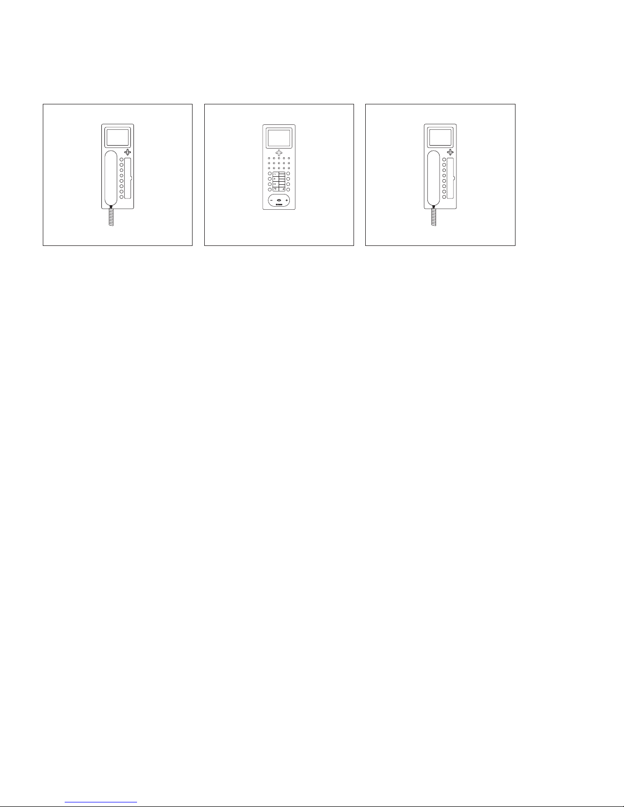
AHT 870-0
Access in-house telephone with door
release button and 7 additional buttons with 2-colour status LED.
All buttons are freely programmable.
The display shows the graphic menu
interface, but not a camera image.
It is possible to upgrade to a fully
functional video station.
With the functions calling, speech,
door release, light, remote switching
and call silencing.
With the additional purchase of
licence ALUV270-..., the AHT870-...
can be converted into a fully functional indoor video device.
Performance features:
• Display 8.8 cm
• Entrance for storey calls
• Exit freely programmable
• Call differentiation between door
calls, storey calls, indoor calls and
concierge calls
• Switching functions
• Status indications
• Can be used with table-top acces-
sory AZTV870-... as a table-top
device
AHF 870-0
Access handsfree telephone with
speech/control button, door release
button and 7 additional buttons
with 2-colour status LED. All buttons
are freely programmable. The display
shows the graphic menu interface,
but not a camera image. It is possible to upgrade to a fully functional
video station.
With the functions calling, speech,
door release, light, remote switching
and call silencing.
With the additional purchase of
licence ALUV270-... the AHF870-...
can be converted into a fully functional indoor video device.
Performance features:
• Display 8.8 cm
• Entrance for storey calls
• Exit freely programmable
• Call differentiation between door
calls, storey calls, indoor calls and
concierge calls
• Switching functions
• Status indications
• Can be used with table-top acces-
sory AZTV870-... as a table-top
device
AHTV 870-0
Access in-house telephone video
with door release button and 7
additional buttons with 2-colour
status LED. All buttons are freely
programmable. The display shows
the camera image and the graphic
menu interface.
With the functions calling, speech,
door release, vision, light, remote
switching and call silencing.
Performance features:
• Display 8.8 cm
• Entrance for storey calls
• Exit freely programmable
• Call differentiation between door
calls, storey calls, indoor calls and
concierge calls
• Switching functions
• Status indications
• Video memory function
• Integrated 5-way control button
• Can be used with table-top acces-
sory AZTV870-... as a table-top
device
Page 13
13
Top
Oben
AHFV 870-0
Access handsfree telephone video
with speech/control button, door
release button and 7 additional buttons with 2-colour status LED. All
buttons are freely programmable.
The display shows the camera image
and the graphic menu interface.
With the functions calling, speech,
door release, vision, light, remote
switching and call silencing.
Performance features:
• Display 8.8 cm
• Entrance for storey calls
• Exit freely programmable
• Call differentiation between door
calls, storey calls, indoor calls and
concierge calls
• Switching functions
• Status indications
• Video memory function
• Integrated 5-way control button
• Can be used with table-top acces-
sory AZTV870-... as a table-top
device
AZTV 870-0
Access table-top accessory for
indoor call stations for converting
from a wall to a table-top device.
Slip-proof console.
AZA 870-0
Access surface-mount accessory, for
professional surface mounting of
Access indoor call stations.
Comprises a connection adapter
and 4 spacers. The raised height is
increased by 8 mm.
AZIO 870-0
Access input/output accessory as
circuit board for integration in an
indoor unit with an additional input/
output.
Page 14
14
System components
Distribution
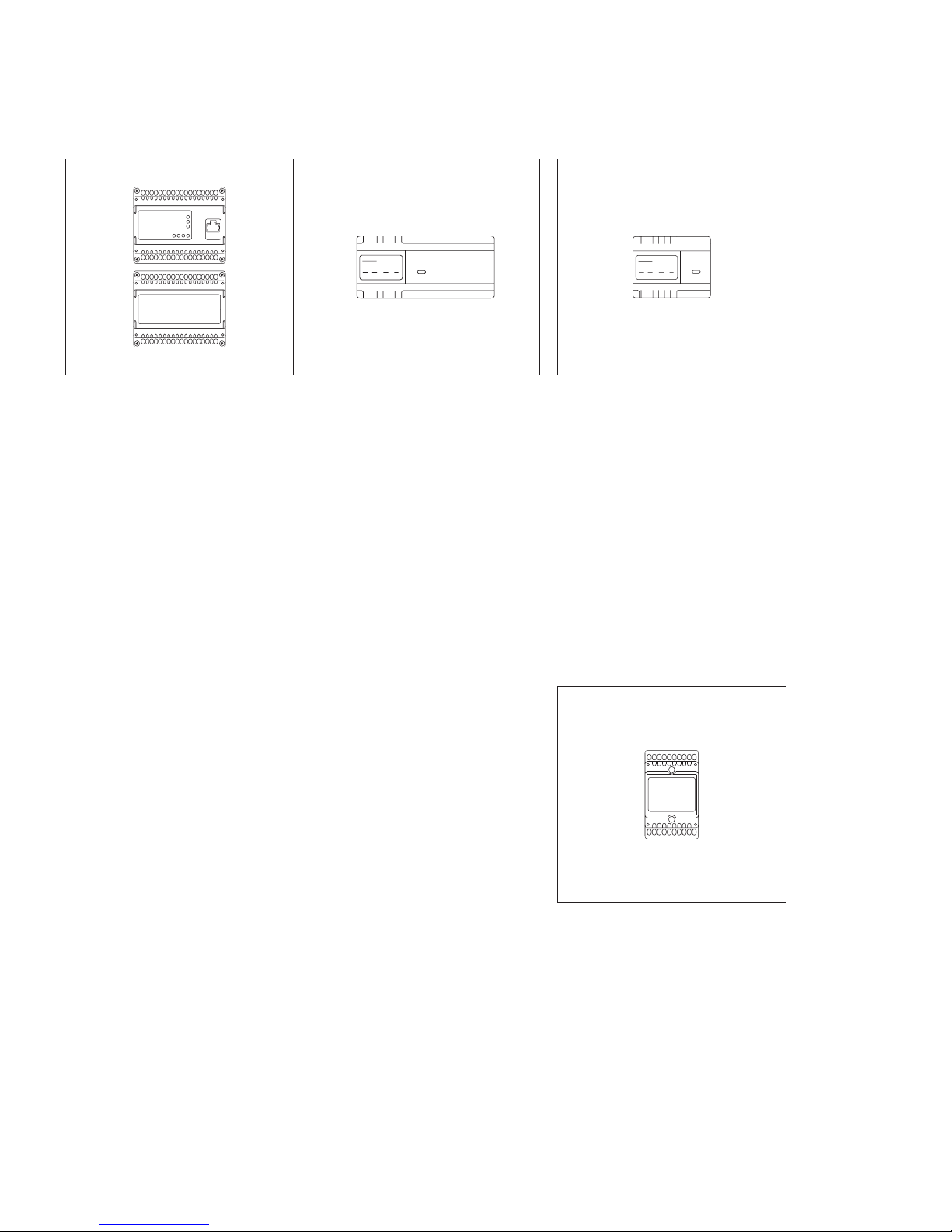
ATLC/NG 670-0
Access door loudspeaker controller
with line rectier in switch panel
housing as an interface for the connection and power supply of door
components to the Access network.
Switch contact for door release
and freely programmable switching
input.
Admissible switching output:
• Light bulbs max. 1300 W
• Fluorescent lamps max. 800 W
• Twin uorescent lamps max.
1200 W
• Parallel compensated uorescent
lamps max. 400 W
VNG 602-02
Video line rectier in a 10-grid
housing.
Primary: 230VAC, 50/60Hz
Secondary: 30VDC, 1.1 A stabi-
lized.
For the supply of individual components such as external cameras.
TR 602-01
Transformer in switch panel housing,
to supply supplementary components.
Operating voltage: 230VAC
+/–10%, 50/60Hz
Output voltage: 12VAC
Output current: max.2.5A
Dimensions (mm) W x H x D:
107 x 89 x 60
TR 603-0
Transformer in switch panel housing,
to supply supplementary components.
Operating voltage: 230VAC
+/–10%, 50/60Hz
Output voltage: 12VAC
Output current: max.1.3A
Dimensions (mm) W x H x D:
53.5x89x60
Page 15
15
AS 670-0 S
Access Server in metal housing, suitable for top hat rail mounting, as a
central unit for management of the
entire Access system; Expansion possible up to 50 users.
More than 10 connections may exist
at any one time in the system.
Commissioning takes place in the
complete system.
Dimensions (mm) W x H x D:
328x88.8x201
AS 670-0 M
Access server in 19“ housing as a
central unit for managing the entire
Access system. Expansion possible
up to 500 users.
More than 10 connections may exist
at any one time in the system.
Commissioning takes place in the
complete system.
Dimensions (mm) W x H x D:
483x88 x 460
AS 670-0 L
Access server in 19“ housing as a
central unit for managing the entire
Access system. Expansion possible
from 500 to over 1000 users.
More than 10 connections may exist
at any one time in the system.
Commissioning takes place in the
complete system.
Dimensions (mm) W x H x D:
483 x 88 x 460
Page 16

16
Software
www.siedle.de/access
ASHT 170-0
Access in-house telephone software,
which graphically depicts a virtual
in-house telephone with video on a
PC monitor.
• Door calls with video are possible
to a Siedle door station.
• Indoor calls possible
• Execution of switching and control
functions such as door release, light
switching etc.
• Display of signals
Function overview:
• Call differentiation between door
calls, storey calls, indoor calls and
concierge calls
• Device and user overview
• Users, doors and devices can be
selected from lists
• Global/private address books
• Video memory function over
licence ALZV 270-...
• Status displays of switchgear
• Switching functions for external
relays
System requirements:
• Microsoft® Windows XP
(from SP3, 32 Bit)
• Microsoft® Windows Vista Home
Premium and Business (from SP1,
32/64 Bit)
• Microsoft® Windows 7 Home
Premium, Professional and Ultimate
(32/64 Bit)
• Intel® Pentium® IV from 2.0 GHz
or compatible CPUs
• min. 2 GB RAM
• Graphics card with at least 128 MB
RAM DirectX 9 support and 16 bit
colour depth
• Ethernet card 100 Mbit
• Sound card including headset
adapter
• .NET Framework 4.0
Page 17

17
www.siedle.de/access
ASC 170-0
Access concierge software, the central interface at the reception desk.
Due to the wide selection of possible
control functions and statuses, and
facility for supporting several calls
and video links, this application is
ideally suited as a communication
switchboard.
Function overview:
• Several audio and video links can
be depicted simultaneously
• Convenient forwarding functions
• Music-on-hold
• Status overview of all Doormatic
door statuses, e.g. activation
enabled day/night switchover
• Convenient switching/control and
display functions
• Camera scan function
• Answering machine functions
System requirements:
• Microsoft® Windows XP (from
SP3, 32 Bit)
• Microsoft® Windows Vista Home
Premium and Business (from SP1,
32/64 Bit)
• Microsoft® Windows 7 Home
Premium, Professional and Ultimate
(32/64 Bit)
• Intel® Pentium® IV from 2.0 GHz
or compatible CPUs
• min. 2 GB RAM
• Graphics card with at least
1280 x 720, 128 MB RAM, DirectX 9
support and 16 bit colour depth
• Ethernet card 100 Mbit
• Sound card including headset
adapter
• .NET Framework 4.0
ASM 170-0
Access software module for integration of Siedle Access in external
systems, e.g. touch panels.
You will be kept up to date with
the latest information by our Project
Sales Department
www.siedle.de/access
Page 18

18
Licences
ALFA 270-0
Access licence for non-Siedle audio
device for connection of a VoIP
audio telephone to the Access
system.
Using a VoIP-ATA adapter, it is also
possible to connect an analog telephone.
The use of non-Siedle devices is subject to Siedle approval.
ALFV 270-0
Access licence for non-Siedle video
device for connection of a VoIP video
telephone to the Access system.
The use of non-Siedle devices is subject to Siedle approval.
ALKNX 270-0 <50
Access KNX connection licence
for importing and managing KNX
addresses. A maximum of 50 data
points can be assigned.
KNX telegrams can be sent and
received.
ALT 270-0
Access telephony connection licence
for utilization of an external connection channel.
A separate licence is required per
channel.
The use of non-Siedle devices is subject to Siedle approval.
ALKNX 270-0 <300
Access KNX connection licence
for importing and managing KNX
addresses. A maximum of 300 data
points can be assigned.
KNX telegrams can be sent and
received.
ALKNX 270-0 <1000
Access licence KNX connection for
the import and management of KNX
addresses; assignment of up to 1000
data points.
KNX telegrams can be sent and
received.
ALFS 270-0
The external smartphone Access
licence permits connection to the
Access server.
A separate licence is required per
device. The smartphone functions as
a mobile indoor device with video.
An additional App is required for
operation. This must be purchased
from the App Store.
ALFT 270-0
The external tablet Access licence
permits connection to the Access
server.
A separate licence is required per
device. The tablet functions as a
mobile indoor device with video. An
additional App is required for operation. This must be purchased from
the App Store.
Page 19

19
External devices
For many requirements and ideas,
the market is ooded by a large
number of devices. Communication
and compatibility between the different components can sometimes
be an issue. For this reason, it is
advisable to make contact at an
early stage with our project sales
department.
We are currently able to offer recommendations for the following areas.
Analogue telephone adapter ATA
SIP telephone
Switch actuators
KNX
VoIP
Interface ISDN telephone system
If required, we are glad to also test
other interesting areas.
Page 20

20
Installation
AS-AV Siedle Vario
Siedle Vario
ATLM 670-...
BTM 650-...
ACM 670-...
ATLM
BTM
23
24
TaV1Ta
Ta
Tb
D2
S2
S1
Ta
Ta
Tb
S3D1S4
V2
Ta
V5
V6
V6
V5
S4
Ta
S3
D2
D1
Tb
Ta
S2
Tb
V2S1V1
Tac1TaTbbcTa
Tb
V2
Tb
V1
Ta
Ta
Tb
V4
Tb
V3
Tö 12 V AC/DC
min. 20 Ohm
L1
230 V AC
N
ACM
ATLC 670-...
ANG 600-...
LAN
a)
m)
b1
IN
Remarks
Device
requirement
Page 21

21
Functional
Calling, speech and video functions
between door station and the connected Access indoor call stations.
An existing call can not be listened in
to or viewed by other Access indoor
call stations. Door release button
for the door release function and 7
other buttons which can be assigned
any optional functions. The denition of functions and the relevant
buttons take place during conguration of the server which assumes the
function of central overall system
administrator. The number of Access
users is determined by the server.
Connection facility for a storey call
button (ERT) for calling an apartment door and potential-free contact is available as standard.
Different ringtones for calling from
the front door, the apartment door,
concierge or internal call.
Supplementary functions
• Internal calls and speech
communication between Access
indoor call stations are possible.
• Connection of an analogue
camera to the ATLC 670-... via the
interface AIVS 670-...
• Concierge function as central
interface, e.g. at the reception
• 8 freely selectable ring tones
• Call forwarding
• Call follow-me function
• Parallel door and storey call
• Group formation possible
• Selective dialling of the door
station using additional free buttons
• Central video memory module
(server) possible
Remarks
a) If door release or door control
systems are installed which do not
correspond to 12 V AC/DC min.
20 Ohm, the system will require an
intermediate relay.
m) Where there are more than 10
BTM 650-... units, an additional
12 V AC supply, for instance
TR 603-..., must be installed due to
the current consumption.
Page 22

22
Installation
AS-AV Siedle Classic
ACM
ATLE
BRMA
Tö 12 V AC
min. 20 Ohm
ATLC 670-...
c1
6
7.1
7.2
7.3
7.11
230 V AC
N
L1
ANG 600-...
+
-
7.12
V2
23
24
V5
D2
S2
S1
D1
S4
S3
V1
V4
V5
V3
V6
V2
V1
S4
D2
D1
S1
S3
S2
LAN
a)
d)
IN
Classic Türstation
ACM 670-...
ATLE 670-...
BRMA 050-...
ACM
ATLE
BRMA
Tö 12 V AC
min. 20 Ohm
ATLC 670-...
c1
6
7.1
7.2
7.3
7.11
230 V AC
N
L1
ANG 600-...
+
-
7.12
V2
23
24
V5
D2
S2
S1
D1
S4
S3
V1
V4
V5
V3
V6
V2
V1
S4
D2
D1
S1
S3
S2
LAN
a)
d)
IN
Classic Türstation
ACM 670-...
ATLE 670-...
BRMA 050-...
ACM
CATLE
BRMA
Tö 12 V AC/DC
min. 20 Ohm
ATLC 670-...
c1
6
7.1
7.2
7.3
7.11
230 V AC
N
L1
ANG 600-...
b1
7.12
V2
23
24
V5
D2
S2
S1
D1
S4
S3
V1
V4
V6V3V5
V2
V1
S4
D2
D1
S1S3S2
LAN
a)
Siedle Classic
ACM 673-...
CATLE 670-...
BRMA 050-...
q)
IN
Device
requirement
Remarks
Page 23

23
Functional
Calling, speech and video functions
between door station and the connected Access indoor call stations.
An existing call can not be listened in
to or viewed by other Access indoor
call stations. Door release button
for the door release function and 7
other buttons which can be assigned
any optional functions. The denition of functions and the relevant
buttons take place during conguration of the server which assumes the
function of central overall system
administrator. The number of Access
users is determined by the server.
Connection facility for a storey call
button (ERT) for calling an apartment door and potential-free contact is available as standard.
Different ringtones for calling from
the front door, the apartment door,
concierge or internal call.
Supplementary functions
• Internal calls and speech communication between Access indoor call
stations are possible.
• Connection of an analogue
camera to the ATLC 670-... via the
interface AIVS 670-...
• Concierge function as central
interface, e.g. at the reception
• 8 freely selectable ring tones
• Call forwarding
• Call follow-me function
• Parallel door and storey call
• Group formation possible
• Selective dialling of the door station using additional free buttons
• Central video memory module
(server) possible
Remarks
a) If door release or door control
systems are installed which do not
correspond to 12 V AC/DC min.
20 Ohm, the system will require an
intermediate relay.
q) The internal wiring of the Classic
door station is completed on site by
the customer.
Page 24

24
Siedle Steel
SATLM 670-...
SACM 670-...
SATLM
23
24
Ta
V1
Ta
TaTbD2
S2
S1
Ta
TaTbS3
D1
S4
V2
Ta
S4
Ta
S3
D2
D1
Tb
S2
Tb
S1
Ta
Tb
V2
Tb
V1
Tö 12 V AC/DC
min. 20 Ohm
N
L1
230 V AC
SACM
ATLC 670-...
ANG 600-...
LAN
a)Remarks
Device
requirement
Buttons
Installation
AS-AV Siedle Steel
Page 25

25
Functional
Calling, speech and video functions
between door station and the connected Access indoor call stations.
An existing call can not be listened in
to or viewed by other Access indoor
call stations. Door release button
for the door release function and 7
other buttons which can be assigned
any optional functions. The denition of functions and the relevant
buttons take place during conguration of the server which assumes the
function of central overall system
administrator. The number of Access
users is determined by the server.
Connection facility for a storey call
button (ERT) for calling an apartment door and potential-free contact is available as standard.
Different ringtones for calling from
the front door, the apartment door,
concierge or internal call.
Supplementary functions
• Internal calls and speech communication between Access indoor call
stations are possible.
• Connection of an analogue
camera to the ATLC 670-... via the
interface AIVS 670-...
• Concierge function as central
interface, e.g. at the reception
• 8 freely selectable ring tones
• Call forwarding
• Call follow-me function
• Parallel door and storey call
• Group formation possible
• Selective dialling of the door station using additional free buttons
• Central video memory module
(server) possible
Remarks
a) If door release or door control
systems are installed which do not
correspond to 12 V AC/DC min.
20 Ohm, the system will require an
intermediate relay.
Page 26

26
Installation
AS-AV Siedle Vario with
supplementary supply
Siedle Vario
ATLM 670-...
BTM 650-...
ACM 670-...
ATLM
BTM
23
24
TaV1Ta
Ta
Tb
D2
S2
S1
Ta
Ta
Tb
S3D1S4
V2
Ta
V5
V6
V6
V5
S4
Ta
S3
D2
D1
Tb
Ta
S2
Tb
V2S1V1
Tac1Ta
Ta
Tb
b
Tb
b1
Ta
Tb
V2
Tb
V1
Ta
Ta
Tb
V4
Tb
V3
Tö 12 V AC/DC
min. 20 Ohm
L1
230 V AC
N N
L1
c
b
230 V AC
ACM
ATLC 670-...
ANG 600-...
LAN
TR 603-...
a)g), k)
c
IN
Remarks
Device
requirement
Page 27

27
Functional
Calling, speech and video functions
between door station and the connected Access indoor call stations.
An existing call can not be listened in
to or viewed by other Access indoor
call stations. Door release button
for the door release function and 7
other buttons which can be assigned
any optional functions. The denition of functions and the relevant
buttons take place during conguration of the server which assumes the
function of central overall system
administrator. The number of Access
users is determined by the server.
Connection facility for a storey call
button (ERT) for calling an apartment door and potential-free contact is available as standard.
Different ringtones for calling from
the front door, the apartment door,
concierge or internal call.
Supplementary functions
• Internal calls and speech communication between Access indoor call
stations are possible.
• Connection of an analogue
camera to the ATLC 670-... via the
interface AIVS 670-...
• Concierge function as central
interface, e.g. at the reception
• 8 freely selectable ring tones
• Call forwarding
• Call follow-me function
• Parallel door and storey call
• Group formation possible
• Selective dialling of the door station using additional free buttons
• Central video memory module
(server) possible
Remarks
a) If door release or door control
systems are installed which do not
correspond to 12 V AC/DC min.
20 Ohm, the system will require an
intermediate relay.
g) Is only required if more than 10
BTM 650-... units are installed at this
door station.
k) If the BTM 650-... units are supplied via a separate transformer, no
connection between c1 and c/b1
and b may exist at the terminal
block.
Page 28

28
AS-AV Siedle Vario with
pilfer safeguard DSC602-0
Siedle Vario
ATLM 670-...
BTM 650-...
ACM 670-...
ATLM
BTM
23
24
TaV1Ta
Ta
Tb
D2
S2
S1
Ta
Ta
Tb
S3D1S4
V2
Ta
V5
V6
V6
V5
S4
Ta
S3
D2
D1
Tb
Ta
S2
Tb
V2S1V1
Tac1Ta
Ta
Tb
b
Tb
c
Ta
Tb
V2
Tb
V1
Ta
Ta
Tb
V4
Tb
V3
Tö 12 V AC/DC
min. 20 Ohm
L1
230 V AC
N N
L1
c
b
230 V AC
ACM
ATLC 670-...
ANG 600-...
LAN
TR 603-...
c
b
M1
M2
DSC 602-...
a)m)
b1
bl
bl
gr
gr
IN
Remarks
Device
requirement
Page 29

29
Functional
Calling, speech and video functions
between door station and the connected Access indoor call stations.
An existing call can not be listened in
to or viewed by other Access indoor
call stations. Door release button
for the door release function and 7
other buttons which can be assigned
any optional functions. The denition of functions and the relevant
buttons take place during conguration of the server which assumes the
function of central overall system
administrator. The number of Access
users is determined by the server.
Connection facility for a storey call
button (ERT) for calling an apartment door and potential-free contact is available as standard.
Different ringtones for calling from
the front door, the apartment door,
concierge or internal call.
The mounting frame can be locked/
unlocked using the DSC602-...
This protects the integrated modules
against unauthorized removal.
Supplementary functions
• Internal calls and speech communication between Access indoor call
stations are possible.
• Connection of an analogue
camera to the ATLC 670-... via the
interface AIVS 670-...
• Concierge function as central
interface, e.g. at the reception
• 8 freely selectable ring tones
• Call forwarding
• Call follow-me function
• Parallel door and storey call
• Group formation possible
• Selective dialling of the door station using additional free buttons
• Central video memory module
(server) possible
Remarks
a) If door release or door control
systems are installed which do not
correspond to 12 V AC/DC min.
20 Ohm, the system will require an
intermediate relay.
m) Where there are more than 10
BTM 650-... units, an additional
12 V AC supply, for instance
TR 603-..., must be installed due to
the current consumption.
Page 30

30
Installation
AS-AV Siedle Vario with external camera
Siedle Vario
ATLM 670-...
BTM 650-...
ATLM
BTM
Ta
S5
L/S
+K
-K
N
L1
+
-
L/S
V6
23
24
Ta
V5
Tb
Ta
V4
Tb
V1V3V2
S7
c
b
c
b
V6
V5
Ta
Ta
V2
Tb
V1
Tb
S4
D2
D1
Ta
Ta
TbD2
D1
Ta
Ta
Tb
S1S3S2
S4
Ta
Ta
Tb
S1S3S2
ATLC 670-...ANG 600-...
CEC 612-... AIVS 670-...
Tö 12 V AC/DC
min. 20 Ohm
b) c)
230 V AC
N
L1
230 V AC
LAN
a)
g), k)
TR 603-...
IN
Remarks
Device
requirement
Page 31

31
Functional
Calling and speech between door
stations and the connected Access
indoor call stations. The external
camera discreetly surveys the access
area from the background.
An existing call can not be listened in
to or viewed by other Access indoor
call stations. Door release button
for the door release function and 7
other buttons which can be assigned
any optional functions. The denition of functions and the relevant
buttons take place during conguration of the server which assumes the
function of central overall system
administrator. The number of Access
users is determined by the server.
Connection facility for a storey call
button (ERT) for calling an apartment door and potential-free contact is available as standard.
Different ringtones for calling from
the front door, the apartment door,
concierge or internal call.
Supplementary functions
• Internal calls and speech communication between Access indoor call
stations are possible.
• Connection of an analogue
camera to the ATLC 670-... via the
interface AIVS 670-...
• Concierge function as central
interface, e.g. at the reception
• 8 freely selectable ring tones
• Call forwarding
• Call follow-me function
• Parallel door and storey call
• Group formation possible
• Selective dialling of the door station using additional free buttons
• Central video memory module
(server) possible
Remarks
a) If door release or door control
systems are installed which do not
correspond to 12 V AC/DC min.
20 Ohm, the system will require an
intermediate relay.
b) Distance between the camera and
AIVS 670-... max. 10m
c) Pay attention to the switch setting
for the supply voltage 12/24VDC
g) Is only required if more than 26
BTM 650-... units are installed at this
door station.
k) If the BTM 650-... units are supplied via a separate transformer, no
connection between c1 and c/b1
and b may exist at the terminal
block.
Page 32

32
Installation
AS-AV with Access custom-t door loudspeaker
and external camera
ATLE
BRMA
Tö 12 V AC/DC
min. 20 Ohm
b), c)
ATLC 670-...
c1
S5
6
7.1
7.2
7.3
7.11
L/S
+K
-K
230 V AC
N
L1
ANG 600-...
+
-
L/S
7.12
V6
23
24
V5
D2
S2
S1
D1
S4
S3
V5
V4
V1V3V2
S7
V2
V1
S4
D2
D1
S1S3S2
CEC 612-... AIVS 670-...
LAN
a)
d), q)
IN
Device
requirement
Remarks
Custom-fit
door loudspeaker
ATLE 670-...
BRMA 050-...
Page 33

33
Functional
Calling and speech between door
stations and the connected Access
indoor call stations. The external
camera discreetly surveys the access
area from the background.
An existing call can not be listened in
to or viewed by other Access indoor
call stations. Door release button
for the door release function and 7
other buttons which can be assigned
any optional functions. The denition of functions and the relevant
buttons take place during conguration of the server which assumes the
function of central overall system
administrator. The number of Access
users is determined by the server.
Connection facility for a storey call
button (ERT) for calling an apartment door and potential-free contact is available as standard.
Different ringtones for calling from
the front door, the apartment door,
concierge or internal call.
Supplementary functions
• Internal calls and speech communication between Access indoor call
stations are possible.
• Connection of an analogue
camera to the ATLC 670-... via the
interface AIVS 670-...
• Concierge function as central
interface, e.g. at the reception
• 8 freely selectable ring tones
• Call forwarding
• Call follow-me function
• Parallel door and storey call
• Group formation possible
• Selective dialling of the door station using additional free buttons
• Central video memory module
(server) possible
Remarks
a) If door release or door control
systems are installed which do not
correspond to 12 V AC/DC min.
20 Ohm, the system will require an
intermediate relay.
b) Distance between the camera and
AIVS 670-... max. 10m
c) Pay attention to the switch setting
for the supply voltage 12/24VDC
d) A maximum of 12call but-
tons can be connected at one
BRMA050-...
The maximum conguration is
16BRMA050-... units/192buttons.
q) The internal wiring of the Classic
door station is completed on site by
the customer.
Page 34

34
Installation
AS-AV with Access custom-t door loudspeaker
and Access camera module
ATLE
BRMA
Tö 12 V AC/DC
min. 20 Ohm
ATLC 670-...
c1
6
7.1
7.2
7.3
7.11
230 V AC
N
L1
ANG 600-...
7.12
V6
23
24
V5
D2
S2
S1
D1
S4
S3
V5
V4
V1
V3
c1
b1
V2
V2
V1
S4
D2
D1
S1S3S2
LAN
a)
d), q)
ACM 670-...
IN
Device
requirement
Remarks
Custom-fit
door loudspeaker
ATLE 670-...
BRMA 050-...
Page 35

35
Functional
Calling, speech and video functions
between door station and the connected Access indoor call stations.
An existing call can not be listened in
to or viewed by other Access indoor
call stations. Door release button
for the door release function and 7
other buttons which can be assigned
any optional functions. The denition of functions and the relevant
buttons take place during conguration of the server which assumes the
function of central overall system
administrator. The number of Access
users is determined by the server.
Connection facility for a storey call
button (ERT) for calling an apartment door and potential-free contact is available as standard.
Different ringtones for calling from
the front door, the apartment door,
concierge or internal call.
Supplementary functions
• Internal calls and speech
communication between Access
indoor call stations are possible.
• Connection of an analogue
camera to the ATLC 670-... via the
interface AIVS 670-...
• Concierge function as central
interface, e.g. at the reception
• 8 freely selectable ring tones
• Call forwarding
• Call follow-me function
• Parallel door and storey call
• Group formation possible
• Selective dialling of the door
station using additional free buttons
• Central video memory module
(server) possible
Remarks
a) If door release or door control
systems are installed which do not
correspond to 12 V AC/DC min.
20 Ohm, the system will require an
intermediate relay.
d) A maximum of 12call but-
tons can be connected at one
BRMA050-...
The maximum conguration is
16BRMA050-... units/192buttons.
q) The internal wiring of the Classic
door station is completed on site by
the customer.
Page 36

36
Installation
AS-AV Siedle Vario with DRM 611-...
Siedle Vario
ATLM 670-...
BTM 650-...
DRM 611-...
ACM 670-...
ATLM
BTM
23
24
Ta
V1
Ta
TaTbD2
S2
S1
Ta
TaTbS3
D1
S4
V2
Ta
V5
V6
V6
V5
S4
Ta
S3
D2
D1
Da
Db
W5
W6
bv
Tb
Ta
S2
Tb
V2
S1
V1
Ta
c1
c
Ta
Ta
Tb
b
Tb
b1
Ta
Tb
V2
Tb
V1
Ta
Ta
Tb
V4
Tb
V3
Tö 12 V AC/DC
min. 20 Ohm
N
L1
230 V AC
ACM
ATLC 670-...
ANG 600-...
N
L1
230 V AC
TR 603-...
LAN
cv
b
c
W4
W3
DRM
a)n)h)
ZWA 640-...
IN
Büchner Claudia
Maier Klaus
Schuhmacher Bernd
Namensuche mit
Büchner Claudia
Maier Klaus
Schuhmacher Bernd
Namensuche mit
Remarks
Device
requirement
Page 37

37
Functional
Calling, speech and video functions
between door station and the connected Access indoor call stations.
With the call button module, the call
goes to a central location (concierge)
or via the display call module selectively to the required user.
An existing call can not be listened in
to or viewed by other Access indoor
call stations. Door release button
for the door release function and 7
other buttons which can be assigned
any optional functions. The denition of functions and the relevant
buttons take place during conguration of the server which assumes the
function of central overall system
administrator. The number of Access
users is determined by the server.
Connection facility for a storey call
button (ERT) for calling an apartment door and potential-free contact is available as standard.
Different ringtones for calling from
the front door, the apartment door,
concierge or internal call.
Supplementary functions
• Internal calls and speech communication between Access indoor call
stations are possible.
• Connection of an analogue
camera to the ATLC 670-... via the
interface AIVS 670-...
• Concierge function as central
interface, e.g. at the reception
• 8 freely selectable ring tones
• Call forwarding
• Call follow-me function
• Parallel door and storey call
• Group formation possible
• Selective dialling of the door station using additional free buttons
• Central video memory module
(server) possible
Remarks
a) If door release or door control
systems are installed which do not
correspond to 12 V AC/DC min.
20 Ohm, the system will require an
intermediate relay.
h) Where there are more than 10
BTM 650-... units, an additional
12 V AC supply, for instance
TR 603-..., must be installed due to
the current consumption.
n) For programming the names, pro-
gramming software PRS602-0 and
programming interface PRI602-0
are required. The names are now
entered in the display call module
using the PRS602-0.
Page 38

38
Installation
AS-AV Siedle Vario with COM 611-...
Siedle Vario
ATLM 670-...
BTM 650-...
COM 611-...
ACM 670-...
ATLM
BTM
14
13
W2
Ta
V1
Ta
TaTbD2
S2
S1
Ta
TaTbS3
D1
S4
V2
Ta
V5
V6
V6
V5
S4
Ta
S3
D2
D1
Da
Db
b
c
bv
Tb
Ta
S2
Tb
V2
S1
V1
Ta
c1
c
Ta
Ta
Tb
b
TaDa
TaW0
TaDb
Tacv
bv
Tb
b1
Ta
Tb
V2
Tb
V1
Ta
Ta
Tb
V4
Tb
V3
N
L1
N
L1
230 V AC
230 V AC
ACM
ATLC 670-...
ANG 600-...TR 603-... EC 602-...
LAN
cv
COM
a)
i), k)d)
Tö 12 V AC/DC
min. 20 Ohm
IN
Büchner Claudia
Maier Klaus
Schuhmacher Bernd
Namensuche mit
Remarks
Device
requirement
Page 39

39
Functional
Calling, speech and video functions
between door station and the connected Access indoor call stations.
With the call button module, the call
goes to a central location (concierge)
or via the code lock module selectively to the user whose stored code
you have entered.
An existing call can not be listened in
to or viewed by other Access indoor
call stations. Door release button
for the door release function and 7
other buttons which can be assigned
any optional functions. The denition of functions and the relevant
buttons take place during conguration of the server which assumes the
function of central overall system
administrator. The number of Access
users is determined by the server.
Connection facility for a storey call
button (ERT) for calling an apartment door and potential-free contact is available as standard.
Different ringtones for calling from
the front door, the apartment door,
concierge or internal call.
Supplementary functions
• Internal calls and speech communication between Access indoor call
stations are possible.
• Connection of an analogue
camera to the ATLC 670-... via the
interface AIVS 670-...
• Concierge function as central
interface, e.g. at the reception
• 8 freely selectable ring tones
• Call forwarding
• Call follow-me function
• Parallel door and storey call
• Group formation possible
• Selective dialling of the door station using additional free buttons
• Central video memory module
(server) possible
Remarks
a) If door release or door control
systems are installed which do not
correspond to 12 V AC/DC min.
20 Ohm, the system will require an
intermediate relay.
d) The COM 611-... is always available for placing calls (by code).
An additional Easikey controller is
only required for this door station if
additional control functions have to
be carried out.
i) This is required with the EC 602-...
or when more than one BTM 650-...
is installed in the door station.
k) If the BTM 650-... units are supplied via a separate transformer, no
connection between c1 and c/b1
and b may exist at the terminal
block.
Page 40

40
Installation
AS-AV external camera
with video distributor
a) b)p)
ATLC 670-...
Ta
S5
L/S
E
D
A
+K
-K
230 V AC
N
L1
ANG 600-...
+
-
L/S
V5
Ta
V6
Tb
Ta
V4
Tb
V1V3V2
S7
V2
Tb
V1
CEC 612-... AIVS 670-...
LAN
Video
Videoverteiler
Remarks
Device
requirement
Page 41

41
Functional
Viewing/monitoring a certain area
using an Access indoor call station
set up for the purpose.
Each camera is specically selected
via the ATLC 670-... The number of
cameras/Access users is limited by
the server used.
Using the buttons dened during
conguration, each camera can be
selected. This function must be con-
gured for every authorized user.
The video signal is split using the
video distributor supplied by the customer. This allows the signal to be
shown on a continuous surveillance
monitor and also on an event-controlled basis on an assigned Access
indoor device.
Terminal assignment of the video
distributor provided by the customer:
E = Input
D = Throughput
A = Output
Remarks
a) Distance between the camera and
AIVS 670-... max. 10m
b) Pay attention to the switch setting
for the supply voltage 12/24VDC
p) Camera in continuous operation
Page 42

42
Installation
AS-AV external camera
p) a) b)
ATLC 670-...
Ta
S5
L/S
+K
-K
230 V AC
N
L1
ANG 600-...
+
-
L/S
V5
Ta
V6
Tb
Ta
V4
Tb
V1V3V2
S7
V2
Tb
V1
CEC 612-... AIVS 670-...
LAN
Remarks
Device
requirement
Page 43

43
Functional
Viewing/monitoring a certain area
using an Access indoor call station
set up for the purpose.
Each camera is specically selected
via the ATLC 670-... The number of
cameras/Access users is limited by
the server used.
Using the buttons dened during
conguration, each camera can be
selected. This function must be con-
gured for every authorized user.
Remarks
a) Distance between the camera and
AIVS 670-... max. 10m
b) Pay attention to the switch setting
for the supply voltage 12/24VDC
p) Camera in continuous operation
Page 44

44
Installation
AS-AA Siedle Vario
Siedle Vario
ATLM 670-...
BTM 650-...
ATLM
BTM
N
11
12
14
L1
23
24
c1
b1
b
c
S4
D2
D1
D2
D1
S1S3S2
S4
S1S3S2
ATLC 670-...ANG 600-...
Tö 12 V AC/DC
min. 20 Ohm
230 V AC
LAN
a)j)
IN
Remarks
Device
requirement
Page 45

45
Functional
Calling and speech between door
stations and the connected Access
indoor call stations.
Other Access indoor call stations are
not able to listen in to an existing
call. Door release button for the
door release function and 7 other
buttons which can be assigned any
optional functions. The denition of
functions and the relevant buttons
take place during conguration of
the server which assumes the function of central overall system administrator. The number of Access users
is determined by the server.
Connection facility for a storey call
button (ERT) for calling an apartment door and potential-free contact is available as standard.
Different ringtones for calling from
the front door, the apartment door,
concierge or internal call.
Remarks
a) If door release or door control
systems are installed which do not
correspond to 12 V AC/DC min.
20 Ohm, the system will require an
intermediate relay.
j) From 26 BTM 650-... units, an
additional 12 V AC, for instance
TR 603-... must be installed due to
the current consumption.
Page 46

46
Installation
AS-AA with Access custom-t door loudspeaker
ATLE
BRMA
ATLC 670-...
6
7.1
7.2
7.3
7.11
230 V AC
N
L1
ANG 600-...
7.12
23
24
D2
S2
S1
D1
S4
S3
S4
D2
D1
S1S3S2
LAN
d), q) a)
Tö 12 V AC/DC
min. 20 Ohm
IN
Remarks
Bus custom-fit
door loudspeaker
ATLE 670-...
BRMA 050-...
Device
requirement
Page 47

47
Functional
Calling and speech between door
stations and the connected Access
indoor call stations.
Other Access indoor call stations are
not able to listen in to an existing
call. Door release button for the
door release function and 7 other
buttons which can be assigned any
optional functions. The denition of
functions and the relevant buttons
take place during conguration of
the server which assumes the function of central overall system administrator. The number of Access users
is determined by the server.
Connection facility for a storey call
button (ERT) for calling an apartment door and potential-free contact is available as standard.
Different ringtones for calling from
the front door, the apartment door,
concierge or internal call.
Remarks
a) If door release or door control
systems are installed which do not
correspond to 12 V AC/DC min.
20 Ohm, the system will require an
intermediate relay.
d) A maximum of 12call but-
tons can be connected at one
BRMA050-...
The maximum conguration is
16BRMA050-... units/192buttons.
q) The internal wiring of the Classic
door station is completed on site by
the customer.
Page 48

48
Installation
Storey call button,
customer‘s own signalling device
Ta
Tb4
5
RJ45 8/8
LAN
e)
Ta
ERT
3
6
Remarks
Device
requirement
Ta
Ta
Tb
Ta
RJ45 8/8
LAN
ERT
3
6
4
5
1
2
7
8
e), f)
Remarks
Device
requirement
Page 49

49
Functional
A storey call button can be connected as standard to every Access
indoor call station. To guarantee
call differentiation between door
and storey calls, a different acoustic
signal is issued for the storey call.
The selection of signals is dened by
the administrator during congura-
tion.
The storey call button is connected
via the RJ45 8/8(8) telecom socket.
The left-hand jack is generally used
for the LAN network. The storey
call button and if applicable the
customer‘s own existing signalling
device are connected using the
right-hand jack.
Remarks
e) A suitable intermediate relay may
be required for the customer‘s own
existing signalling device.
f) By mounting accessory
AZIO 870-... terminals 1 and 2 as
well as 7 and 8 of the right-hand
RJ45 telecom socket are occupied,
as listed in the terminal assignment.
The terminal assignment changes if
a different accessory is mounted.
An indoor device may only be connected to the network using an
RJ458/8(8) network socket.
Terminal assignment
Link RJ45 socket
1 - 8 LAN
Right RJ45 socket
3
6
Storey call button ERT
4
5
Switching contact
30 V, 1 A
1
2
Input via
potential-free contact
7
8
Switching contact
30 V, 1 A
Page 50

50
Information on programming
The Access system is programmed
using a computer running the current Firefox browser at the server.
The necessary programming is
carried out directly at the server
using the web user interface. Any
necessary support for programmingrelated questions can be found in
the help function.
Careful documentation of the
system and any conguration-related
requirements with an indication of
the device mounting locations is particularly helpful and should be made
a constituent part of the operating
manual without fail.
Operating manual
To ensure that you can retrace the
status of a system at any time, an
operating manual should be drawn
up and regularly maintained.
Siedle recommends compiling an
operating manual to document the
network and the Access system.
The operating manual must be
accessible to servicing personnel and
contain fundamental information:
• Contact data of the system administrator (with deputization arrangements)
• Hardware list
• Documentation of the server con-
guration
• Server backup
• Documentation of the software
status and device conguration
• Construction plan with structured
cabling (LAN policy)
• Issue of passwords and possibilities
for remote login access
• IP address and device names of the
network components
• Process descriptions (e.g. creating
a user, exchanging devices etc.)
• Documentation of changes made
• Documentation of errors/remedy
of errors
Licence management
Through the purchase of additional licences, more services can be
purchased for specic devices or for
the system as a whole. These can be
purchased exclusively through our
Access Certied Partners, who will
then enable the licences for you.
To nd the responsible Access
Certied Partner, go to
www.siedle.com
Page 51

51
Initial commissioning/Login
Requirements:
PC with installed browser (Firefox,
latest version)
The PC and Access Server must be
in the same network/linked using a
crossover cable
Registration at the administrator
user interface
Login via a web interface takes place
on the Access server. For this, enter
the IP address of the server. This is
dened as 192.168.1.1 in the as-
delivered status.
The administrator set in the factory
has the account name „admin“ and
the password „admin“. In addition,
a randomly generated security code
is required with each login.
Kontoname
Kennwort
Sicherheitscode
http://www.siedle.de
admin
•••••
hsnc
Anmelden Abbrechen
hsnc
This is entered in the security code
eld. If the security code is not legible, click onto it to generate a new
code. Start the login process using
the „login“ button. Further con-
guration is prompted by the server
instructions and using the integrated
help function.
Page 52

52
Servicing
Service requirement
Access systems are serviced by the
regional Access Certied Partner
(service specialists). Customers/
administrators request this services
as the need arises.
For services specialists, access must
be afforded to all parts of the system
at all times. The administrator and all
necessary documents appertaining
to the system must be available for
the duration of the servicing work.
Safety remarks
Mounting, installation and servicing
work on electrical devices may only
be performed by a suitably qualied
electrician. Failure to observe this
regulation could result in the risk of
serious damage to health or fatal
injury due to electric shocks.
Electrical voltage
As a result of electrostatic charging,
direct contact with the circuit board
can result in destruction of the
device. Direct contact with the circuit
board must therefore be avoided.
Exchanging devices
All devices which are connected
directly to the network (indoor
devices and ATLC 670-...) can be
exchanged in running operation.
Procedure:
• The administrator overwrites the
MAC address for the device with the
MAC address of the new replacement device in the server.
• Exchange the defective device.
The conguration remains
unchanged, making the function
identical with the predecessor
device.
Exchanging ATLM/ATLE 670-...
Procedure:
• Only the line rectier which sup-
plies the ATLC670-... has to be
disconnected from the mains. The
Access system can remain operational.
• Exchange the defective ATLM/
ATLE670-...
• Switch the line rectier back on.
The system is now completely ready
to resume operation. No conguration is required.
Exchanging a defective server
AS 670-...
Procedure:
• Sever all connections to the mains
and the power supply.
• Exchange the defective server and
restore all the connections
• Set up the supplied licences on the
new server
• Restore the backup of the current
conguration. If no backup exists,
the system must be recongured.
Update process
The update is initialized by the
administrator and centrally executed
at the server for all the devices. It
is not possible to carry out an individual update of a single internal
device or the server.
During the update process, the
entire system is non-operational. No
calls or functions can be initiated
or received. Updates should therefore be carried out during periods
of minimal activity and with suf-
cient advance notice. The update
operation of the internal devices is
optically displayed by all the buttons lighting up in yellow. After the
update is complete, the devices are
automatically restarted.
During the update process, the
power supply to the devices must
not be interrupted, as this can result
in damage. In this case, a repeat
update is no longer possible, and the
devices will have to be sent in for
repair.
Page 53

53
Start process
The start process can be initiated
centrally by the administrator at the
server. Unplugging and reconnecting
the internal devices also initiates a
restart. The Access door loudspeaker
controller can be restarted by briey
disconnecting the relevant line
rectier or by actuating the reset
button. The reset button can only be
accessed by opening the housing.
A restart of the internal devices is
signalled by a yellow ashing light,
starting with button 8 and ending
with button 6, and the display lights
up in white. If the start is successful
and when the device has received
all the information from the server,
the system goes to the operating
status. In the event of a fault, e.g.
the internal device is not congured,
all the buttons light up continuously
in red.
Page 54

54
ATLC 670-0
SN 0000000000
IP 20
Access Türlautsprecher-Controller
Access Door loudspeaker controller
Access Contrôleur de platine de rue
Link
Status
Error / OK
A1 A2 A3
E
23 24 13 14 15 16 17 18 S1 S2 S3 S4 D1 D2 V1 V2
Output Input ATLM/ACM
LED 1
LED displays
ATLC 670-0
LED display LED operating status Function
LED 1 off no operating voltage
lights up in green operating voltage applied
Link lights up in green connection to switch exists
flashes green data communication with the device
off no connection to the switch
Status lights up in green Vario bus ready for operation
flashes green data communication in the Vario bus
Error/OK lights up briefly in green after Power On for around 5 seconds
flashes green during ramp-up, flashing starts up
appr. 20 seconds after Power On
lights up in green ATLC is logged in at the server
lights up in red error logging into server
A1 lights up in green output 1 HIGH (DR)
off output 1 LOW (DR)
A2 lights green output 2 HIGH
off output 2 LOW
A3 lights up in green output 3 HIGH (LI)
off output 3 LOW
E lights up in green input 1 HIGH (LI)
off input 1 LOW
Page 55

55
LED 1
LED 4
LED 5
LED 8
LED 1
LED 8
LED 1
AHTV/AHFV 670-0
LED display LED operating status Function
LED 8 ashes yellow Searching for the server
off server found
LED 7 ashes yellow loading conguration from server
off export successfully completed
LED 6 ashes yellow login to server
off login successful
LED 1-8 lights up briey in yellow after Power On for around 5 seconds
lights up in red error logging into server
off successfully logged into server
LED 1-8 Flashes for appr. 2 mins. in yellow Software update for terminals
ATLM 670-0
LED display LED operating status Function
LED 1 ashes 3x in green Device starts up
Off Ramp up successfully completed
Lights up green Audio active
Flashes briey 3x in green unassigned/unprogrammed
call button is actuated
Page 56

56
Glossary
Telecom socket RJ45 8/8
The left-hand jack is used for the
LAN network. The storey call button
and if applicable the customer’s own
existing signalling device are connected using the right-hand jack.
Operating manual
Current system documentation
including all hardware and software
requirements.
CAT5
Twisted pair cable, shielded
Storey call button
The storey call button (ERT) is used
to call from a storey door to the
internal device.
Indoor devices
Call stations and accessories as an
intercom to the door area.
LAN
Local Area Network Network which
connects the system components.
Licences
Enabling performance characteristics which are additionally managed
centrally on the server.
POE
Power over Ethernet supplies all
internal devices.
System components
All devices which are connected
together in the system.
Software
The system software is pre-installed
on the server. The software for the
concierge and virtual telephone
functions or for connection to
external systems must be additionally purchased if required.
Switch
Coupling element which links the
network components and segments.
Door area
In the door area are all devices
connected to the system via an
Access door loudspeaker controller
ATLC670-... This also includes cameras which monitor different areas.
Doormatic
Programmable function which actuates a contact in the ATLC 670-...
with a time delay (door release).
Distribution
This is the place where several
devices are switched together (connected). This often takes place in a
distributor cabinet, although this is
not mandatory. Large distribution
panels can ll an entire room.
Page 57

57
Technical additions or printing errors
do not constitute grounds for compensation claims.
After-sales service:
Telephone +49 7723 63-540
access@siedle.de
To supplement this system manual,
you will nd the latest edition in the
download area of our website on
www.siedle.com
Index
ACM 670-... 10
AHF 870-... 12
AHFV 870-... 13
AHT 870-... 12
AHTV 870-... 12
AIVS 670-... 11
ALFA 270-... 18
ALFC 270-... 18
ALFS 270-... 18
ALFT 270-... 18
ALFV 270-... 18
ALKNX 270-... 18
ALT 270-... 18
ANG 600-... 14
AS 670-... 15
ASC 170-... 17
ASHT 170-... 16
ASM 170-... 17
ATLC 670-... 14
ATLC/NG 670-... 14
ATLE 670-... 9
ATLM 670-... 8
AZA 870-... 13
AZIO 870-... 13
AZTV 870-... 13
BRMA 050-01 9
BTM 650-... 8
CEC 612-... 10, 32, 34
COM 611-... 8, 38
DRM 611-... 8, 36
KA/WG 950-... 10
Siedle Cassic 9, 22
Siedle Steel 9, 24
TR 602-... 14
TR 603-... 14
Page 58

58
Page 59

59
Page 60

S. Siedle & Söhne
Telefon- und Telegrafenwerke OHG
Postfach 1155
78113 Furtwangen
Bregstraße 1
78120 Furtwangen
Telefon +49 7723 63-0
Telefax +49 7723 63-300
www.siedle.de
info@siedle.de
© 2011/03.15
Printed in Germany
Best. Nr. 0-1101/142961 EN
 Loading...