

SSS Siedle MOM 711-0, MOM 711-1 Installation Manual
Produktinformation
Monitor
MOM 711-0 und
MOM 711-1
Monitor
MOM 711-0 and
MOM 711-1
Moniteur
MOM 711-0
MOM711_0_01_021843 20.09.2002 8:00 Uhr Seite 1
4
English
Mounting
Application
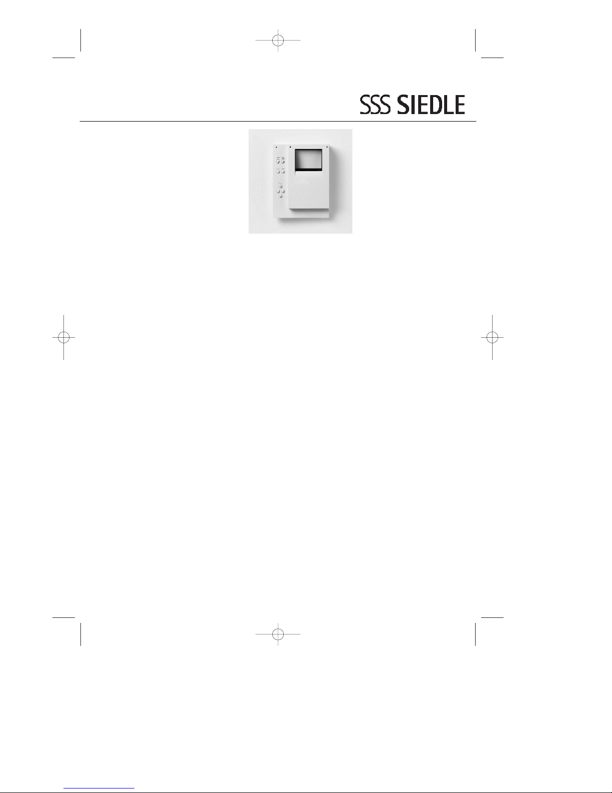
The monochrome monitor
MOM 711-0 with 4,2 ” screen
diagonal is generally designed for
surface wall mounting. However, it
can also be mounted in combination
with the intercom system as a flushmounted or table-top unit.
The MOM 711-... can also be used
as an image memory by integration
of the video memory module
ZVM 711-... . This permits the auto-
matic storage of up to 32 video
images together with the time and
date.
Camera control
The connected cameras CMM and
CMC 511/ 611-... can be
horizontally and vertically swivelled
by up to
± 20° using 4 integrated control
buttons.
Remark
A separate flush-mounted switch
box should be mounted under each
monitor to accommodate the
surplus supply cable. The most
favourable viewing angle is achieved
by mounting the screen at eye level.
Lighting conditions must also be
taken into consideration. The
incidence of light directly on the
screen diminishes the contrast.
Wall mounting
The MOM 711-... can be surface
mounted without the need for
accessories.
1 Open the units.
2 (not illustrated)
Detach the light current connector
and 2-pin flat connector on the
coaxial cable from the base plate.
3 Fasten the unit on the wall.
4 (not illustrated)
Connect in accordance with the
relevant wiring diagram.
5 Plug the light current connector
and the 2-pin flat connector on the
coaxial cable back into the base
plate and shut the housing again.
Note relating to the MOM 711-...
with video 2-wire bus!
When using the MOM 711-... in
conjunction with the video 2-wire
bus (VBE 650-...) and the video
memory module accessory
ZVM 711-..., the settings of the
sliding switch in the VBE 650-... as
described under Point 14 in the VBE
product information and
additionally the following settings
in the MOM 711-… must be performed:
Set the BCD switch to „0“
(timer off).
Leave the jumper JP2 „Continuous
operation“ in place.
When using without ZVM 711-...
no external power supply is required.
In this case the BCD switch must be
set to „0“ and the jumper JP2
„Continuous operation“ must be
removed.
Remark:
When using Video 2-wire VE 511-...
please note the relevant product
information.
Mounting the combination
HT 611-..., HTS/HTC/HTA 711-...,
BTS/BTC 750-..., T 611-... or
SIC and MOM 711-...
6 Open the units.
7 (not illustrated)
Detach the light current connector
and the 2-pin flat connector on the
coaxial cable from the base plate of
the MOM 711-... .
8 Break away the prepared
connecting web „a“ in the housing
bases and screw the bases together
using the 2 connecting elements
provided with the monitor.
9 Fix the units on the wall and
connect in accordance with the
relevant wiring diagram.
10 Connect the provided 7-pole
connecting cable for the
HT 611-...
11 Connect the provided 7-pole
connecting cable for the
SIC 3000-... or T 611-10.
12 Connect the HTS/HTC 711-... or
connect the BTS/ BTC 750-...
13 Comparison of
MO 611-.../MOM/MOC 611-.../
MOM 711-...
14 Plug the light current connector
and the 2-pin flat connector on the
coaxial cable into the base plate of
the MOM 711-... and close the
housing again.
15 User interface of the
MOM 711-...
a Screen
b Image contrast controller
c Image brightness controller
d Switching on the monitor
e Button switches off the monitor
f Buttons for camera control
g BCD switch to set the timer
element. Can only be set with the
upper part of the housing removed.
Settings
0 = 0 Sec. (timer off)
1 = 10 Sec.
2 = 20 Sec.
3 = 30 Sec.
4 = 40 Sec.
5 = 50 Sec.
6 = 60 Sec.
7 = 90 Sec.
8 = 120 Sec.
9 = 180 Sec.
Default status
3 = 30 Sec.
Commissioning
By pressing the call button on the
door loudspeaker, the image
appears on the monitor. The brightness and contrast controller are used
to adjust the picture quality. The
camera CMM/CMC 511/611-... can
be moved horizontally and vertically
by ± 20. Using the "Play" and
"Reset" buttons, the monitor can be
immediately switched on and off
respectively. In systems with video
privacy circuit, the "play" button is
not operational. By mounting the
Video Memory Module ZVM 711-... ,
these buttons are required for image
reproduction (Play) and for deleting
stored images (Reset). Check the
setting of the timer element in the
monitor and change if necessary.
MOM711_0_01_021843 20.09.2002 8:00 Uhr Seite 4
 Loading...