

Page 1
Produktinformation
Farb-CCD-Video-Kamera
KA/WG 950-0 C
Colour CCD video camera
KA/WG 950-0 C
Caméra vidéo CCD
couleur
KA/WG 950-0 C
Telecamera CCD a colori
KA/WG 950-0 C
Kleuren-CCD-VideoCamera
KA/WG 950-0 C
CCD-farvevideokamera
KA/WG 950-0 C
Färg-CCD-videokamera
KA/WG 950-0 C
Page 2
2
3
1
Page 3
4
a
b
b
e
c
a
d
5
6
Page 4
Deutsch
Montage
Anwendung
Die Farb-CCD-Video-Kamera ist für
die Montage im Aussenbereich geeignet. Sie ist wettergeschützt, mit
einem Sonnendach und thermostatisch geregelter Heizung.
Sockelgehäuse mit Kugelkopf und
innenliegender Kabelführung. Die
Anschlussleitungen für die Versorgung und die Koaxleitung sind
steckerfertig montiert; ca.10 cm
lang. Befestigungsmaterial und
Inbusschlüssel liegen der Kamera
bei. Die Einstellung von Zoom und
Focus ist über Tasten direkt an der
Kamera möglich.
Elektrische Spannung
Einbau, Montage und Servicearbeiten elektrischer Geräte
dürfen ausschließlich durch eine
Elektro-Fachkraft erfolgen.
• Bitte lesen Sie diese Produktinformation, bevor Sie die Kamera in Betrieb nehmen.
• Betreiben Sie die Kamera nicht
außerhalb der angegebenen Temperatur-, Feuchtigkeits- oder Spannungsgrenzwerte.
• Bei der Verlegung der Anschlusskabel ist darauf zu achten, dass
diese nicht belastet, geknickt oder
beschädigt werden.
Folgende Einbausituationen müssen
unbedingt vermieden werden:
• direktes Gegenlicht
• direkte Sonneneinstrahlung
• Bildhintergrund mit großer
Helligkeit
• stark reflektierende Wände auf der
gegenüberliegenden Seite der
Kamera
• Leuchten bzw. direkte Lichtquellen
im Blickfeld der Kamera
Elektrostatische Aufladung
Durch elektrostatische Aufladung
kann bei direktem Kontakt mit der
Leiterplatte das Gerät zerstört
werden. Vermeiden Sie daher ein
direktes Berühren der Leiterplatte.
Lieferumfang
• KA/WG 950-...
• 3 Kreuzschlitzschrauben 5 x 50
• 3 Dübel D = 6 mm
• Inbusschlüssel Größe 3
• Zugentlastung mit 2 Schrauben
• 8 Verschlussstopfen
• diese Produktinformation
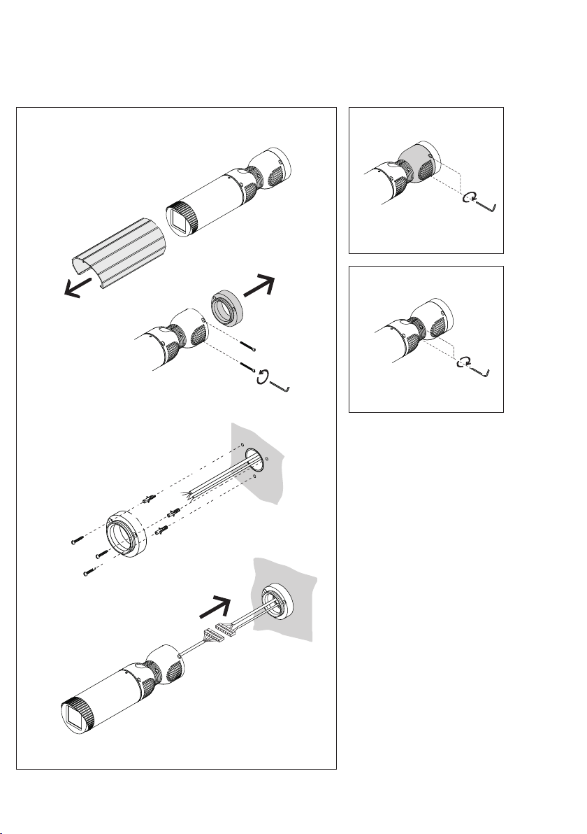
Montage
1 - Sonnendach abnehmen.
- Befestigungsschrauben des
Montagesockels entfernen.
- Montagesockel an der Wand
montieren. Bohrschablone auf der
Klappseite verwenden.
- Versorgungsleitung und Koaxkabel
der Hausinstallation am 6-poligen
Steckverbinder der Kamera anschließen und die Überlänge der Anschlussleitung im Sockelgehäuse
verstauen. Mit der Zugentlastung
das Installationskabel am Kamerafuß
festschrauben.
2 Kamera auf dem Montagesockel
aufsetzen, die Befestigungsschrauben mit wenig Druck ansetzen und
festschrauben.
3 Entsprechende Feststellschrauben
lösen, Kamera auf den Aufnahmebereich ausrichten und fixieren.
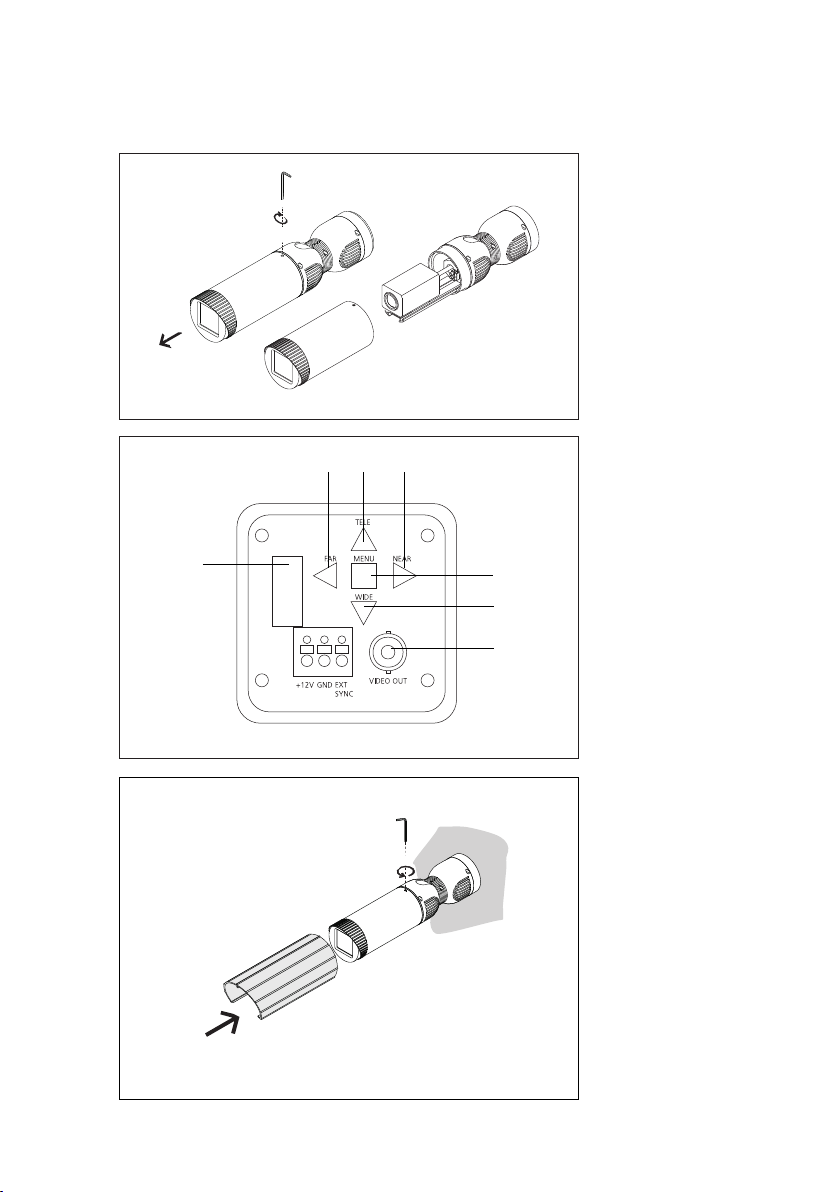
Zoom und Fokus einstellen
4 Durch Eindrehen der Madenschraube Kameragehäuse öffnen
(rechtsdrehend) und Schutzgehäuse
abnehmen.
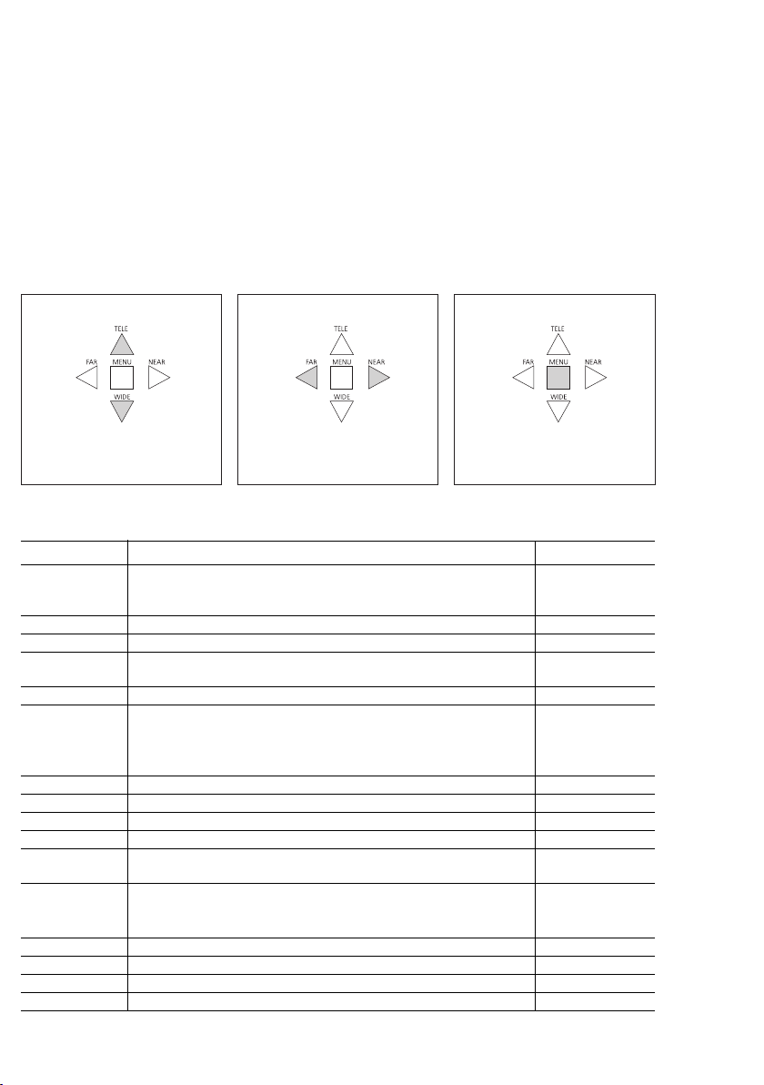
5 Mit den Tasten auf der Rückseite
der Kamera werden Zoom und Focus
eingestellt. Diese Einstellungen können direkt an der Kamera ausgeführt
werden.
a) TELE/WIDE
Einstellung des optischen Zoombereich
b) FAR/NEAR Einstellung des Focus
c) MENU Auswahl von
Menüfunktionen in der OSDAnzeige
d) BNC-Anschluss, Videosignal 1Vss
e) RS485-Schnittstelle für
Ansteuerung über PC
Weitere Einstellungen
Weitere Einstellungen der Kamera
sind über ein OSD-Bildschirm-Menü
(On-Screen-Display) möglich. Um die
Einstellungen vorzunehmen, muss
das Videosignal der Kamera an
einem Monitor angeschlossen
werden. Auf dem Monitor ist das
Menü der Kamera zu sehen. Die
einstellbaren Menüpunkte sind auf
den beiden nächsten
sehen.
6 Gehäuse schließen, verschrauben
und Sonnendach über das Kameragehäuse schieben. Die sichtbaren
Inbusschrauben können mit den
beiliegenden Verschlussstopfen
abgedeckt werden.
Klemmenbelegung
Schwarz =
Rot = + Versorgung
Braun/
= Lb, Hz Versorgung für
Orange
Koax =
Seiten zu
- Versorgung
20 – 30 V DC
die Heizung 12V AC
S/L Schirm/Leiter
2
Page 5

Installation
Installation und Inbetriebnahme ist
im Systemhandbuch 1+n-System
beschrieben (liegt dem Netzgerät
NG/VNG 602-... bei).
Technische Daten:
• Bildaufnahme Farb-CCD-Sensor
1/4“; 752 (H) x 582 (V) 440.000
Bildpunkte
• Manuelles Zoom-Objektiv
3,8 - 83 mm mit Autofocus
• Blickwinkel 50°
• Lichtempfindlichkeit
0,8 Lux bei F 1,6
• Auflösung horizontale
480 TV-Linien
• Videosignal 1 Vss FBAS an 75 Ohm
• Anschluss-Kabel im Wandarm
• Temperaturbereich -20°C bis
+40°C
• Spannungsversorgung 20-30 V/DC
max. 250 mA
• Elektronisch geregelte 12 V AC/DC
Heizung ca. 7 W
• Schutzart IP 66
• Schutzart IK > 10
• Farbe Weiß
• Abmessungen: Ø 90 x 388 mm
Länge mit Wandarm,
Ø 113 x 420,5 mm mit
Sonnendach und Wandarm
- 2,5°
Zubehör für KA/WG 950-...
• ZNF 950-... Zubehör Netzteil-Fuß
zur Versorgung mit 230 V AC. Der
Anschluss der Kamera erfolgt über
Steckverbindungen.
• Netzanschluss 230 V AC / 50 Hz,
+6% – 10%; 160 mA,
• Schutzart IP 66
• Abmessungen: Ø 90 x 65 mm
Pflegehinweise
Reinigen Sie die Kamera und das
Kamerafenster nur mit einem mit
milder Seifenlösung angefeuchteten,
weichen Tuch. Trockene Reinigung,
aggressive Reiniger und Scheuermittel können die Oberfläche beschädigen.
3
Page 6
Menü der Kamera zur
Programmierung
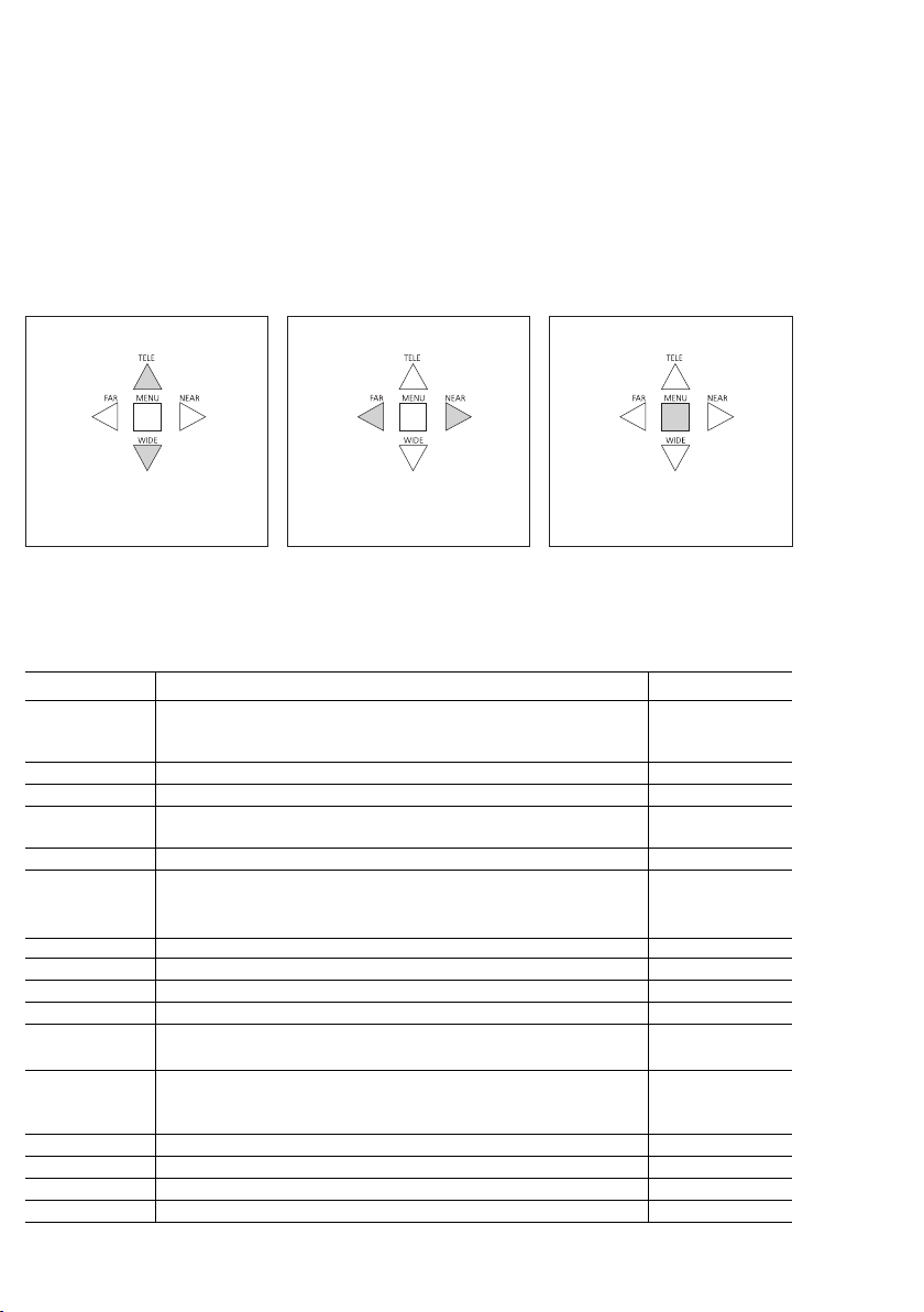
Innerhalb des Menüs erfolgt die
Bedienung mit den Pfeil-Tasten der
Kamera.
Drücken der Taste MENU zeigt die
aktuellen Einstellungen der Kamera
an.
• Um in das Hauptmenü zu gelangen, die Taste MENU erneut
drücken. Mit einem hellgrauen
Balken am linken Bildschirmrand ist
die Auswahl der Funktion möglich.
• Blättern innerhalb des Menüs mit
den Tasten TELE/WIDE. Auswahl
einer Funktion mit MENU.
• Zurück aus einem Menüpunkt mit
der Taste FAR.
Blättern im Menü
Name Funktion Werkseinstellung
WB (Weißabgleich)
AWB Automatischer Weißabgleich.
INDOOR Weißabgleich in Innenräumen.
OUTDOOR Weißabgleich im Außenbereich.
MANUAL R/B Manueller Abgleich Rot- und Grünanteil, kann mit den Tasten
NEAR und FAR geändert werden. Zum Speichern MENU drücken.
WAWB Automatischer Weißabgleich für Weitwinkel.
AE (Shutter)
AUTO Automatische Einstellung von Blende, Shutter und
Verstärkungsregelung (AGC).
IRIS PRI Einstellung der Blende.
SHUTTER PRI Einstellung der Shutterzeit.
AGC Einstellung der automatischen Verstärkung (Automatic Gain Controll).
MANUAL Einstellung von IRIS, Shutter und AGC.
LOW SHUT Aktiviert/Deaktiviert den Low-speed Shutter. Die Betriebsart
kann im Menü PRESET -> SHOT verändert werden.
BLC (Gegenlichtkompensation)
DEFAULT Gegenlichtkompensation in der Bildmitte.
ADJ TOP Gegenlichtkompensation linker und oberer Bildbereich.
ADJ BOTTOM Gegenlichtkompensation rechter und unterer Bildbereich.
LEVEL Einstellung Gegenlichtkompensation zwischen 0 - 90. 30
OFF Deaktiviert die Gegenlichtkompensation.
Rechts/Links-Tasten
Enter-Taste
4
Page 7

TITLE (Kameratitel)
TITLE MENU Der Kamera kann ein Namen zugewiesen werden. 0000
ABCDEF...- Zeichentabelle, Einstellung mit den Tasten TELE, WIDE, NEAR und FAR.
CMD <--> Position des Namens auf dem Bildschirm .
< > SE Speichern mit S, Verlassen des Menüpunkt mit E.
DISPLAY (Anzeige)
DSIP 0 Nur Kameranamen und Indentnummer werden angezeigt.
DSIP 1 Kameranamen und Indentnummer und Zoomposition werden angezeigt.
DSIP 2 Alle Einstellungen der Kamera werden angezeigt.
DSIP PUSH ON Anzeige auf dem Bildschirm für 4 – 6 Sekunden.
CAM SET (ID Nummer)
ID Einstellung der Kamera Identnummer.
BPS Einstellung der Baudrate 9600/19200 bps, wenn RS485 benutzt wird.
BRIGHTNESS Einstellung der Helligkeit zwischen 0 – 90. 30
SHARPNESS Einstellung der Schärfe zwischen 0 – 20. 10
DISTANCE Focussierung des Objektives (min. 0,1 m).
MAX LOWSHUT Einstellung des max. Low-Shutter-Wertes (x2 – x60).
EFFECT (Effekte)
D-ZOOM Digitaler Zoom EIN/AUS.
NEGA/POSI Auswahl Negativ- oder Positivbild.
B/W Darstellung des Kamerabild in Farbe oder Schwarzweiß.
MIRROR Spiegelung des Kamerabild in horizontaler Richtung.
PIP Bild-in-Bild Einblendung Ein oder Aus. (Während das große Bild
FREEZE Schaltet zwischen aktuellem und eingefrorenem Bild um.
PRESET (Einstellungen)
FOCUS Auswahl von automatischem Focus (AUTO) oder manuellem
SYNC Auswahl von interner Synchronisation oder
INIT Initialisierung nach Netzreset. Auswahl der werksseitigen
LOAD Laden der werksseitigen Einstellungen.
SAVE Speichern der ausgewählten Einstellungen. Im Menü INIT
DNR Aktivierung der digitalen Rauschreduzierung.
SHOT Auswahl zwischen Normal, digitaler Bildstabilisierung, erweitertem
eingefroren ist, wird das aktuelle Bild im Ausschnitt dargestellt.
(MANUAL) Focus. Bei Dauerbetrieb der Kamera sollte der
automatische Focus nicht verwendet werden. Die Lebensdauer
der Kamera kann dadurch reduziert werden.
Netzsynchronisation (nur 24 V AC).
Einstellungen oder der individuellen Einstellungen.
muss PRESET ausgewählt sein.
Dynamikbereich oder Low-speed Shutter. Die digitale Bildstabilisierung
ist bei 2-fachem digitalem Zoom aktiv. Die digitale Rauschreduzierung
ist in Standbild, langer Belichtungszeit und bei erweitertem
Dynamikbereich deaktiviert.
END (Menü verlassen)
5
Page 8
English
Mounting
Application
The colour CCD video camera is
suitable for mounting in outdoor
locations. It is weather protected,
has a sun shade and a thermostatically controlled heating system.
Plinth housing with ball head and
internal wiring. The connecting
cables for supply and the coaxial
conductor are mounted ready for
plug-in connection; appr. 10 cm
long. The camera comes with
fastening material and an Allen key.
It is possible to set the zoom and
focus using buttons directly at the
camera.
Electrical voltage
Mounting, installation and
servicing work on electrical
devices may only be performed
by a suitably qualified electrician.
• Please read through this product
information carefully before
commissioning the camera.
• Never operate the camera outside
the specified limiting temperature,
humidity or voltage values.
• When laying the connecting cable,
ensure that it is not subject to load,
kinked or damaged in any way.
The following installation situations
must be avoided without fail:
• Direct backlight
• Direct sunlight
• Very bright picture background
• Highly reflective walls opposite the
camera
• Luminaires or direct light sources
within the camera's field of vision
Electrostatic charging
Electrostatic charging can cause
irreparable damage to the circuit
board as a result of direct contact.
For this reason, direct contact with
the circuit board must be avoided.
Scope of supply
• KA/WG 950-...
• 3 recessed head screws 5 x 50
• 3 wall plugs D = 6 mm
• Allen key size 3
• Cable strain relief with two screws
• 8 sealing plugs
• This product information
Mounting
1 - Remove the sunshade.
- Remove the fastening screws of
the mounting plinth.
- Fix the mounting plinth on the
wall. Use the supplied drilling
template on the fold-out page.
- Connect the supply line and coaxial
cable of the house installation at the
6-pin plug-connector of the camera
and stow any surplus length of the
connecting cable in the plinth
housing. Fasten the installation cable
at the camera foot using the cable
strain relief.
2 Place the camera on the mounting
plinth, apply the fastening screws
using moderate pressure and
tighten.
3 Release the relevant fastening
screws, align the camera with the
surveillance area and fix.
Setting the zoom and focusing
4 By screwing in the grub screws,
open the camera housing (turning to
the right) and remove the protective
housing.
5 Using the buttons at the back of
the camera, set the zoom and focus.
These settings can be executed
directly at the camera.
a) TELE/WIDE
Setting the optical zoom area
b) FAR/NEAR Setting the focus
c) MENU Selection of menu
functions in the OSD display
d) BNC connection, video signal
1Vss
e) RS485 interface for actuation via
the PC
Other settings
Other camera settings can be carried
out using an OSD (On-ScreenDisplay) menu. To carry out these
settings, the video signal of the
camera must be connected to a
monitor. The camera menu can be
seen on the monitor. The menu
points with setting facility are shown
on the next two pages.
6 Close the housing, screw back
together and push the sunshade
over the camera housing. The visible
Allen screws can be covered using
the provided sealing plugs.
Terminal assignment
Black = - supply
Red = + supply
Brown/
Orange = Lb, Hz
Coaxial
20 - 30 V DC
Supply for the
heating 12V AC
= S/L
Shield/Conductor
6
Page 9

Installation
Installation and commissioning are
described in the 1+n system manual
(provided with line rectifier
NG/VNG 602-... ).
Specifications:
• Image pick-up colour CCD sensor
1/4“; 752 (H) x 582 (V) 440,000
pixel
• Manual zoom lens attachment
3.8 - 83 mm with autofocus
• Aperture angle 50°
• Light sensitivity
0.8 Lux at F 1.6
• Horizontal resolution
480 TV lines
• Video signal 1 Vss FBAS at 75 Ohm
• Cable connection in wall arm
• Temperature range -20° to +40°C
• Power supply 20-30 V/DC
max. 250 mA
• Electronically controlled
12 V AC/DC heating appr. 7 W
• Protection system IP 66
• Protection system IK > 10
• Colour white
• Dimensions: dial. 90 x 388 mm
length with wall arm,
dia. 113 x 420.5 mm with
sunshade and wall arm
Accessories for KA/WG 950-...
• ZNF 950-... Line rectifier foot
accessory for supplying with
230 V AC. The camera is connected
by means of plug-in connectors.
• Mains power 230 V AC / 50 Hz,
+6% – 10%; 160 mA,
• Protection system IP 66
• Dimensions: dia. 90 x 65 mm
- 2.5°
Care of your camera
Only ever clean the camera and
camera window using a soft cloth
dampened with a mild soap
solution. Dry cleaning, aggressive
cleaning agents and abrasives can
damage the surface.
7
Page 10
Camera programming menu
The camera's arrow buttons are
used for navigation within the
menu.
Press the MENU button to show the
current camera settings.
• To reach the main menu, press the
MENU button again. If there is a
light grey bar at the left-hand side of
the screen, the relevant function can
be selected.
• Use the TELE/WIDE buttons to
scroll through the menu. Select a
function using MENU.
• Return to a menu point with the
FAR button.
Scrolling through the menu
Name Function Default setting
WB (White balance)
AWB Automatic white balance.
INDOOR White balance in indoor rooms.
OUTDOOR White balance in outdoor areas.
MANUAL R/B Manual red and green component balance, can be changed using the
buttons NEAR and FAR. To save, press MENU.
WAWB Automatic white balance for wide angles.
AE (Shutter)
AUTO Automatic shutter and iris setting and automatic gain control (AGC).
IRIS PRI Iris setting.
SHUTTER PRI Shutter time setting.
AGC Automatic gain control setting.
MANUAL Iris, shutter and ACG setting.
LOW SHUT Activates/Deactivates the low-speed shutter. The operating mode
can be changed in the PRESET -> SHOT menu.
BLC (Backlight compensation)
DEFAULT Backlight compensation in the centre of the picture.
ADJ TOP Backlight compensation at the left and top of the picture.
ADJ BOTTOM Backlight compensation at the right and bottom of the picture.
LEVEL Setting the backlight compensation between 0 - 90. 30
OFF Deactivates the backlight compensation function.
Right/left buttons
Enter button
8
Page 11

TITLE (Camera title)
TITLE MENU The camera can be assigned a name. 0000
ABCDEF...- Symbol table, setting using buttons TELE, WIDE, NEAR and FAR.
CMD <--> Position of the name on the screen.
< > SE Save with S, quit the menu point with E.
DISPLAY (Display)
DSIP 0 Only camera names and ident numbers are displayed.
DSIP 1 Camera names and ident numbers as well as zoom position is displayed.
DSIP 2 All camera settings are displayed.
DSIP PUSH ON Display on screen for 4 – 6 seconds.
CAM SET (ID number)
ID Setting the camera ID number.
BPS Setting the baud rate 9600/19200 bps, if RS485 is being used.
BRIGHTNESS Setting the brightness level between 0 – 90. 30
BRIGHTNESS Setting the sharpness level between 0 – 20. 10
DISTANCE Focusing the lens attachment (at least 0.1 m).
MAX LOWSHUT Setting of the max. low shutter value (x2 – x60).
EFFECT (Effects)
D-ZOOM Digital zoom ON/OFF.
NEGA/POSI Selection of negative or positive picture.
B/W Depiction of the camera image in colour or monochrome.
MIRROR Mirroring the camera picture in the horizontal direction.
PIP Picture-in-picture view on or off. (While the large picture is
FREEZE Switches between the current and the frozen picture.
PRESET (Settings)
FOCUS Selection of automatic focus (AUTO) or manual
SYNC Selection of internal synchronization or
INIT Initialization following a mains power reset. Selection of default
LOAD Loads the default settings.
SAVE Saves the selected settings. In the INIT menu
DNR Activates the digital noise reduction.
SHOT Selection between normal, digital picture stabilization, extended
frozen, the current picture is superimposed in a window).
(MANUAL) focus. In continuous operation of the camera,
automatic focus should not be used. The service life
of the camera can be compromised as a result.
mains synchronization (only 24 V AC).
settings or individual settings.
PRESET must be selected.
dynamic range or low-speed shutter. Digital picture stabilization
is active with 2-step digital zoom. Digital noise reduction
is deactivated in stationary pictures, with a long exposure time and with
an extended dynamic range.
END (Quits the menu)
9
Page 12

Français
Montage
Application
La caméra vidéo CCD couleur est
conçue pour être montée à
l'extérieur. Elle est protégée contre
les intempéries, avec un toit de
protection contre le soleil et un
chauffage à régulation thermostatique. Boîtier socle avec tête
sphérique et passage de câble
intérieur. Les câbles de raccordement destinés à l'alimentation et le
câble coaxial sont montés prêts à
être branchés; longueur 10 cm
environ. Le matériel de fixation et
une clé mâle coudée pour vis à six
pans creux sont livrés avec la
caméra. Le réglage du zoom et du
foyer est possible directement sur la
caméra, par l'intermédiaire de
touches.
Tension électrique
L'installation, le montage et
l'entretien d'appareils électriques
ne doivent être réalisés que par
un spécialiste en électricité.
• Avant de mettre la caméra en
service, veuillez lire la présente
information produit.
• Ne pas utiliser la caméra en dehors
des valeurs limites de température,
d'humidité ou de tension indiquées.
• Au moment de poser les câbles de
raccordement, veiller à ne pas les
charger, les plier ou les
endommager.
Les situations de montage suivantes
doivent impérativement être évitées:
• Contre-jour direct
• Rayonnement direct du soleil
• Arrière-plan d'une grande
luminosité
• Parois fortement réfléchissantes du
côté opposé de la caméra
• Lampes ou sources de lumière
directe dans le champ de vision de la
caméra
10
Charge électrostatique
La charge électrostatique peut
détruire l'appareil en cas de contact
direct avec la carte de circuits
imprimés. Evitez par conséquent
tout contact direct avec la carte de
circuits imprimés.
Etendue de la fourniture
• KA/WG 950-...
• 3 vis à empreinte cruciforme
5 x 50
• 3 chevilles D = 6 mm
• Clé mâle coudée pour vis à six
pans creux taille 3
• Décharge de traction avec 2 vis
• 8 bouchons de fermeture
• La présente information produit
Montage
1 - Déposer le toit de protection
contre le soleil.
- Retirer les vis de fixation du socle
de montage.
- Monter le socle de montage au
mur. Utiliser le gabarit de perçage
sur le côté rabattable.
- Raccorder le câble d'alimentation
et le câble coaxial de l'installation
intérieure au connecteur 6 pôles de
la caméra et ranger la longueur de
câble de raccordement en surplus
dans le socle. Avec la décharge de
traction, visser le câble d'installation
sur le piétement de la caméra.
2 Placer la caméra sur le socle de
montage, mettre en place les vis de
fixation moyennant une légère
pression, et les visser.
3 Desserrer les vis d'arrêt
correspondantes, ajuster la caméra
sur la zone support et la fixer.
Régler le zoom et le foyer
4 En vissant la vis sans tête, ouvrir le
boîtier de la caméra (en tournant à
droite) et déposer le boîtier de
protection.
5 Les touches prévues sur la face
arrière de la caméra permettent de
régler le zoom et le foyer. Ces
réglages peuvent être effectués
directement sur la caméra.
a) TELE/WIDE
Réglage de la plage de zoom
optique
b) FAR/NEAR Réglage du foyer
c) MENU Sélection de fonctions de
menu sur l'afficheur OSD (Affichage
à l'Ecran)
d) Raccord BNC, signal vidéo 1Vss
e) Interface RS485 pour commande
par l'intermédiaire du PC
Autres réglages
D'autres réglages de la caméra sont
possibles par l'intermédiaire d'un
menu écran OSD (On-ScreenDisplay, Affichage à l'Ecran).
Pour effectuer les réglages, il faut
raccorder le signal vidéo de la
caméra à un moniteur. Sur le
moniteur, on peut voir le menu de la
caméra. Les points de menu
réglables sont indiqués sur les deux
pages suivantes.
6 Fermer le boîtier, le visser, et faire
glisser le toit de protection contre le
soleil sur le boîtier de la caméra. Les
vis à six pans creux visibles peuvent
être recouvertes par les bouchons de
fermeture joints à la fourniture.
Implantation des bornes
Noir = - Alimentation
Rouge = + Alimentation
Brun/
orange
Koax
(Coax.) = S/L Blindage/conducteur
20 – 30 V CC
= Lb, Hz
Alimentation du
chauffage 12V CA
Page 13

Installation
L'installation et la mise en service
sont décrites dans le manuel système
1+n (joint au bloc d'alimentation
NG/VNG 602-...).
Caractéristiques techniques:
• Prise de vues capteur CCD couleur
1/4“; 752 (H) x 582 (V) 440.000
points d'image
• Objectif zoom manuel
3,8 - 83 mm avec Autofocus
• Angle de visée 50°
• Sensibilité à la lumière
0,8 Lux en F 1,6
• Résolution horizontale
480 lignes TV
• Signal vidéo 1 Vss FBAS sur
75 ohms
• Câble de raccordement dans le
bras de montage mural
• Plage de températures
-20°C à +40°C
• Alimentation en tension
20-30 V/CC
max. 250 mA
• Chauffage 12 V CA/CC à
régulation électronique, env. 7 W
• Indice de protection IP 66
• Indice de protection IK > 10
• Couleur blanc
• Dimensions : Ø 90 x 388 mm de
longueur avec bras de montage
mural, Ø 113 x 420,5 mm avec toit
de protection contre le soleil et bras
de montage mural
- 2,5°
Conseils d'entretien
Pour nettoyer la caméra et la vitre de
la caméra, n'utiliser qu'un chiffon
doux humidifié d'une solution
savonneuse non agressive. Un
nettoyage à sec, un détergent
agressif et un produit abrasif
peuvent endommager la surface.
Accessoire pour KA/WG 950-...
• ZNF 950-... Accessoire piétement
bloc d'alimentation pour
alimentation en 230 V CA. Le
raccordement de la caméra
s'effectue par l'intermédiaire de
connecteurs.
• Raccordement secteur
230 V CA / 50 Hz, +6% - 10% ;
160 mA,
• Indice de protection IP 66
• Dimensions : Ø 90 x 65 mm
11
Page 14

Menu de la caméra pour la
programmation
On évolue dans le menu à l'aide des
touches flèches de la caméra.
Un appui sur la touche MENU
permet d'afficher les réglages
actuels de la caméra.
• Pour accéder au menu principal,
appuyer de nouveau sur la touche
MENU. La fonction peut être
sélectionnée à l'aide d'une barre gris
clair sur le bord gauche de l'écran.
• Pour parcourir le menu, utiliser les
touches TELE/WIDE. Sélection d'une
fonction avec MENU.
• Pour sortir d'un point de menu,
appuyer sur la touche FAR.
Parcours du menu
Nom Fonction Réglage en usine
WB (Ajustement du blanc)
AWB Ajustement automatique du blanc.
INDOOR Ajustement du blanc à l'intérieur.
OUTDOOR Ajustement du blanc à l'extérieur.
MANUAL R/B L'ajustement manuel du pourcentage de rouge et de vert peut être
modifié à l'aide des touches NEAR et FAR. Pour mémoriser,
appuyer sur MENU.
WAWB Ajustement automatique du blanc pour grand angle.
AE (Shutter) (Obturateur)
AUTO Réglage automatique du diaphragme, de l'obturateur et
réglage de l'amplification (AGC) (Réglage Automatique du Gain).
IRIS PRI Réglage du diaphragme.
SHUTTER PRI Réglage du temps de fermeture.
AGC Réglage de l'amplification automatique (Automatic Gain Control)
(Réglage Automatique du Gain).
MANUAL Réglage de IRIS (iris), Shutter (obturateur) et AGC
(réglage automatique du gain).
LOW SHUT Active/désactive le Low-speed Shutter (obturateur basse vitesse).
Le mode d'utilisation peut être modifié dans le menu PRESET -> SHOT.
BLC (Compensation du contre-jour)
DEFAULT Compensation du contre-jour au centre de l'image.
ADJ TOP Compensation du contre-jour zones gauche et supérieure de l'image.
ADJ BOTTOM Compensation du contre-jour zones droite et inférieure de l'image.
LEVEL Réglage de la compensation du contre-jour entre 0 et 90. 30
OFF Désactive la compensation du contre-jour.
Touches droite/gauche
Touche Entrée
12
Page 15

TITLE (Titre de la caméra)
TITLE MENU Un nom peut être attribué à la caméra. 0000
ABCDEF...- Tableau de signes, réglage à l'aide des touches TELE, WIDE, NEAR et FAR.
CMD <--> Position du nom sur l'écran.
< > SE S pour mémoriser, E pour quitter le point de menu.
DISPLAY (Afficheur)
DSIP 0 Seuls le nom de la caméra et le numéro d'identification s'affichent.
DSIP 1 Seuls le nom de la caméra et le numéro d'identification, ainsi que la ,
DSIP 2 Tous les réglages de la caméra s'affichent.
DSIP PUSH ON Affichage à l'écran pendant 4 - 6 secondes.
CAM SET (Numéro ID (identification))
ID Réglage du numéro d'identification de la caméra.
BPS Réglage du débit en bauds 9600/19200 bps, si l'on utilise RS485.
BRIGHTNESS Réglage de la luminosité entre 0 et 90. 30
SHARPNESS Réglage de la netteté entre 0 et 20. 10
DISTANCE Mise au point de l'objectif (min. 0,1 m).
MAX LOWSHUT Réglage de la valeur Low-Shutter max. (x2 – x60).
EFFECT (Effets)
D-ZOOM MARCHE/ARRET zoom numérique.
NEGA/POSI Sélection image négative ou image positive.
B/W Représentation de l'image de la caméra en couleur ou en noir et blanc.
MIRROR Réflexion de l'image de la caméra dans le sens horizontal.
PIP Marche ou arrêt incrustation image dans image. (Pendant que la grande
FREEZE Passage entre image actuelle et image gelée.
position du zoom s'affichent.
image est gelée, l'image actuelle est présentée dans le cadrage).
PRESET (Réglages)
FOCUS Sélection du foyer automatique (AUTO) ou du
foyer manuel (MANUAL). Lorsque la caméra fonctionne en permanence,
il ne faut pas utiliser le foyer automatique. La durée de vie
de la caméra peut en être diminuée.
SYNC Sélection de la synchronisation interne ou
de la synchronisation secteur (24 V CA seulement).
INIT Initialisation après reset secteur. Sélection des réglages
effectués en usine ou des réglages individuels.
LOAD Chargement des réglages effectués en usine.
SAVE Mémorisation des réglages sélectionnés. Dans le menu INIT,
PRESET doit être sélectionné.
DNR Activation de la réduction de bruit numérique.
SHOT Sélection entre normal, stabilisation d'image numérique,
zone dynamique élargie ou Low-speed Shutter. La stabilisation d'image
numérique est active dans le cas du zoom numérique double.
La réduction de bruit numérique est désactivée en image fixe, à un temps
d'exposition long et dans la plage dynamique élargie.
END (Quitter le menu)
13
Page 16

Italiano
Montaggio
Modo d'uso
La telecamera CCD a colori è adatta
per il montaggio in ambienti esterni.
E' protetta contro le intemperie,
provvista di tettuccio parasole e
riscaldamento con regolazione
termostatica. Zoccolo con testa
sferica e passacavi interno. I cavi di
collegamento per l'alimentazione e il
cavo coassiale sono montati già
completi di connettore; lunghezza
circa 10 cm. I dispositivi di fissaggio
e la chiave per viti ad esagono cavo
sono forniti in dotazione con la
telecamera. Lo zoom e la messa a
fuoco possono essere impostati con
gli appositi tasti direttamente sulla
telecamera.
Tensione elettrica
Gli interventi di installazione,
montaggio e assistenza agli
apparecchi elettrici devono
essere eseguiti esclusivamente
da elettricisti specializzati.
• Si prega di leggere il presente
opuscolo informativo sul prodotto
prima di mettere in funzione la
telecamera.
• Non azionare la telecamera oltre i
valori limite di tensione, umidità e
temperatura indicati.
• Durante la posa del cavo di
connessione accertarsi di non
sovraccaricare, piegare o
danneggiare il cavo.
Evitare assolutamente le seguenti
situazioni di montaggio:
• Controluce diretta
• Raggi del sole diretti
• Sfondo d'immagine molto
luminoso
• Parete molto riflettente sul lato
antistante la telecamera
• Luci o fonti di luce dirette nel
campo di ripresa della telecamera
Carica elettrostatica
In caso di contatto diretto con il
circuito stampato, la carica
elettrostatica può danneggiare
irrimediabilmente l'apparecchio.
Evitare, pertanto, un contatto diretto
con il circuito stampato.
Kit di fornitura
• KA/WG 950-...
• 3 viti con intaglio a croce 5 x 50
• 3 tasselli D = 6 mm
• Chiave per viti ad esagono cavo
misura 3
• Scarico di tradizione con 2 viti
• 8 tappi
• Il presente opuscolo informativo
sul prodotto
Montaggio
1 - Smontare il tettuccio parasole.
- Rimuovere le viti di fissaggio dello
zoccolo di montaggio.
- Montare lo zoccolo di montaggio
alla parete. Utilizzare la dima di
foratura sul lato ribaltabile.
- Collegare il cavo di alimentazione e
il cavo coassiale dell'impianto
dell'edificio al connettore a 6 poli
della telecamera e sistemare la
lunghezza in eccesso del cavo di
connessione nello zoccolo. Avvitare il
cavo di installazione alla base della
telecamera con lo scarico di trazione.
2 Applicare la telecamera sullo
zoccolo di montaggio, inserire le viti
di fissaggio con leggera pressione e
serrarle.
3 Allentare le corrispondenti viti di
fermo, orientare la telecamera
secondo il campo di ripresa e
fissarla.
Impostazione dello zoom e della
messa a fuoco
4 Ruotando (a destra) la vite senza
testa, aprire la scatola della
telecamera e smontare l'involucro di
protezione.
5 Con i tasti sul lato posteriore della
telecamera impostare lo zoom e la
messa a fuoco. Queste impostazioni
possono essere eseguite
direttamente sulla telecamera.
a) TELE/WIDE
Impostazione del range di zoom
ottico
b) FAR/NEAR Impostazione della
messa a fuoco
c) MENU Selezione di funzioni di
menu nella visualizzazione OSD
d) Collegamento BNC, segnale video
1Vss
e) Interfaccia RS485 per il comando
tramite PC
Altre impostazioni
Le altre impostazioni della
telecamera possono essere eseguite
tramite un menu sullo schermo OSD
(On-Screen-Display). Per eseguire le
impostazioni, occorre collegare il
segnale video della telecamera ad un
monitor. Sul monitor si può vedere il
menu della telecamera. Le voci di
menu impostabili sono riportate
nelle due pagine successive.
6 Chiudere e avvitare la scatola e
spingere il tettuccio parasole sulla
scatola della telecamera. Le viti ad
esagono cavo visibili possono essere
coperte con i tappi forniti in
dotazione.
Assegnazione dei morsetti
Nero = alimentazione -
= alimentazione
Rosso
Marrone/
arancio = Lb, Hz
Coas. = S/L schermatura/
20 – 30 V DC
Alimentazione per
il riscaldamento
12V AC
conduttore
+
14
Page 17

Installazione
L'installazione e la messa in funzione
sono descritte nel manuale del
sistema 1+n (allegato
all'alimentatore NG/VNG 602-...).
Dati tecnici:
• Ripresa con sensore CCD a colori
da 1/4“; 752 (post.) x 582 (ant.)
440.000 pixel
• Obiettivo zoom manuale
3,8 - 83 mm con autofocus
• Angolo di ripresa 50°
• Fotosensibilità
0,8 Lux a F 1,6
• Risoluzione orizzontale
480 linee TV
• Segnale video Vss FBAS a 75 Ohm
• Cavo di connessione nel braccio a
muro
• Range di temperatura da
-20°C a +40°C
• Alimentazione di tensione
20-30 V/DC
max. 250 mA
• Riscaldamento a regolazione
elettronica 12 V AC/DC, circa 7 W
• Classe di protezione IP 66
• Classe di protezione IK > 10
• Colore bianco
• Dimensioni: Ø 90 x 388 mm di
lunghezza con braccio a muro,
Ø 113 x 420,5 mm con
tettuccio parasole e braccio a muro
- 2,5°
Accessorio per KA/WG 950-...
• ZNF 950-... Alimentatore
accessorio per un'alimentazione di
230 V AC. L'allacciamento della
telecamera avviene mediante
collegamenti a spina.
• Collegamento alla rete da
230 V AC / 50 Hz, +6% – 10%;
160 mA,
• Classe di protezione IP 66
• Dimensioni: Ø 90 x 65 mm
Istruzioni per la pulizia
Pulire la telecamera e l'obiettivo
della telecamera esclusivamente con
un panno morbido inumidito con
soluzione saponata delicata.
Procedure di pulizia a secco,
detergenti aggressivi e mezzi abrasivi
possono danneggiare la superficie
dell'apparecchio.
15
Page 18

Menu della telecamera per la
programmazione
La navigazione all'interno del menu
avviene con i tasti freccia della
telecamera.
Premendo il tasto MENU vengono
visualizzate le impostazioni della
telecamera.
• Per entrare nel menu principale,
premere di nuovo il tasto MENU.
Grazie alla barra di colore grigio
chiaro sul bordo sinistro dello
schermo è possibile selezionare la
funzione desiderata.
• Sfogliare il menu con i tasti
TELE/WIDE. Selezionare una
funzione con il tasto MENU.
• Uscire da una voce di menu con il
tasto FAR.
Scrolling del menu
Nome Funzione Impostazione di
fabbrica
WB (Bilanciamento del bianco)
AWB Bilanciamento automatico del bianco.
INDOOR Bilanciamento del bianco in ambienti interni.
OUTDOOR Bilanciamento del bianco in ambienti esterni.
MANUAL R/B Il bilanciamento manuale del guadagno del rosso e del verde può essere
modificato con i tasti NEAR e FAR. Per salvare premere il tasto MENU.
WAWB Bilanciamento automatico del bianco per il grand'angolo.
AE (Otturatore)
AUTO Impostazione automatica di IRIS, otturatore e regolazione del controllo
automatico delguadagno (AGC).
IRIS PRI Impostazione dell'IRIS.
SHUTTER PRI Impostazione del tempo dell'otturatore.
AGC Impostazione del controllo automatico del guadagno
(Automatic Gain Control).
MANUAL Impostazione dell'IRIS, dell'otturatore e dell'AGC.
LOW SHUT Attiva/disattiva l'otturatore low-speed. La modalità operativa può
essere modificata nel menu PRESET -> SHOT.
BLC (Compensazione del controluce)
DEFAULT Compensazione del controluce al centro dell'immagine.
ADJ TOP Compens. del controluce nella zona sinistra e superiore dell'immagine.
ADJ BOTTOM Compens. del controluce nella zona destra e inferiore dell'immagine.
LEVEL Impostazione compensazione del controluce fra 0 e 90. 30
OFF Disattiva la compensazione del controluce.
16
Tasti freccia destra/freccia sinistra
Tasto invio
Page 19

TITLE (Denominazione della telecamera)
TITLE MENU E' possibile assegnare un nome alla telecamera. 0000
ABCDEF...- Tabella dei simboli, impostazione con i tasti TELE, WIDE, NEAR e FAR.
CMD <--> Posizione del nome sullo schermo.
< > SE Si salva con S, si esce dalla voce di menu con E.
DISPLAY (Visualizzazione)
DSIP 0 Vengono visualizzati solo il nome della telecamera e il numero di
DSIP 1 Vengono visualizzati il nome della telecamera, il numero di identificazione
DSIP 2 Vengono visualizzate tutte le impostazioni della telecamera.
DSIP PUSH ON Visualizzazione sullo schermo per 4 – 6 secondi.
CAM SET (Numero ID)
ID Impostazione del numero di identificazione della telecamera.
BPS Impost. del baudrate 9600/19200 bps, se si utilizza l'interfaccia RS485.
BRIGHTNESS Impostazione della luminosità fra 0 e 90. 30
SHARPNESS Impostazione della nitidezza fra 0 e 20. 10
DISTANCE Messa a fuoco dell'obiettivo (min. 0,1 m).
MAX LOWSHUT Impostazione del valore max. di low-shutter (x2 – x60).
EFFECT (Effetti)
D-ZOOM Zoom digitale ON/OFF.
NEGA/POSI Selezione immagine negativa o positiva.
B/W Rappresentazione dell'immagine della telecam. a colori o in bianco e nero.
MIRROR Riflessione dell'immagine della telecamera in direzione orizzontale.
PIP Attivazione o disattivazione della funzione immagine nell'immagine.
FREEZE Commuta fra immagine corrente e immagine congelata.
identificazione.
e la posizione dello zoom.
(Mentre l'immagine grande è congelata, viene visualizzato il particolare
dell'immagine corrente.
PRESET (Impostazioni)
FOCUS Selezione della messa a fuoco automatica (AUTO) o della messa a fuoco
manuale (MANUAL). In caso di funzionamento continuato della
telecamera, non utilizzare la messa a fuoco automatica. Il mancato
rispetto di questa avvertenza può ridurre la vita utile della telecamera.
SYNC Selezione della sincronizzazione interna o
della sincronizzazione di rete (solo 24 V AC).
INIT Inizializzazione dopo il reset della rete. Selezione delle impostazioni
di fabbrica oppure delle impostazioni personalizzate.
LOAD Caricamento delle impostazioni di fabbrica.
SAVE Salvataggio delle impostazioni selezionate. Nel menu INIT
deve essere selezionato PRESET.
DNR Attivazione della riduzione digitale del rumore.
SHOT Selezione fra normale, stabilizzazione digitale dell'immagine,
gamma dinamica estesa o otturatore low-speed. La stabilizzazione
digitale dell'immagine è attiva in caso di zoom digitale 2x. La riduzione
digitale del rumore è disattivata in caso di fermo immagine, tempo di
esposizione lungo e gamma dinamica estesa.
END (Uscita dal menu)
17
Page 20

Nederlands
Montage
Gebruik
De Kleuren-CCD-Video-Camera is
voor de montage in het buitenbereik
geschikt. Zij is weerbestendig, met
een zonnescherm en thermostatisch
geregelde verwarming.
Sockelbehuizing met kogelkop en
binnenin liggende kabeldoorvoer. De
aansluitleidingen voor de verzorging
en de coaxleiding zijn steekklaar
gemonteerd; ca.10 cm lang.
Bevestigingsmateriaal en inbussleutel
zijn meegeleverd bij de camera. De
instelling van zoom en focus is via de
toetsen direct op de camera
mogelijk.
Electrische spanning
Inbouw, montage en
onderhoudswerkzaamheden aan
electrische apparaten mogen
uitsluitend door een elektrovakman worden uitgevoerd.
• Leest u a.u.b. deze
productinformatie, voordat u de
camera in gebruik neemt.
• Gebruikt u de camera niet buiten
de aangegeven temperatuur-,
vochtigheids of spanningsgrenswaarden.
• Bij het plaatsen van de
aansluitkabels dient erop gelet te
worden, dat deze niet worden
belast, geknikt of beschadigd.
De volgende inbouwsituaties dienen
absoluut vermeden te worden:
• direct tegenlicht
• direct inkomende zonnenstralen
• beeldachtergrond met grote
helderheid
• sterk reflecterende muren aan de
tegenovergestelde kant van de
camera
• lampen resp. directe lichtbronnen
in het blikveld van de camera
Elektrostatische lading
Door electrostatische lading kan bij
een direct contact met de printplaat
het apparaat worden vernietigd.
Vermijdt u daarom het directe
aanraken van de printplaat.
Leveringsomvang
• KA/WG 950-...
• 3 Kruiskopschroeven 5 x 50
• 3 Duvel D = 6 mm
• Inbussleutel maat 3
• Treknoktlasting met 2 schroeven
• 8 Afsluitingsstoppen
• Deze productinformatie
Montage
1 - Zonnescherm afnemen.
- Bevestigingsschroeven van de
montagesockel verwijderen.
- Montagesockel op de muur
monteren. Boorsjabloon op de
kiepzijde gebruiken.
- Vorzorgingsleiding en coaxkabel
van de huisinstallatie op de 6-polige
steekverbinding van de camera
aansluiten en de overgebleven
lengte van de aansluitleiding in de
sockelbehuizing opbergen. Met de
trekontlasting de installatiekabel op
de cameravoet vastschroeven.
2 Camera op de montagesockel
plaatsen, de bevestigingsschroeven
met enige druk aanzetten en vastschroeven.
3 Betreffende stelschroeven losmaken, camera op het opnamebereik richten en fixeren.
Zoom en focus instellen
4 Door indraaien van de tapschroef
de camerabehuizing openen
(rechtsdraaied) en beschermende
behuizing verwijderen.
5 Met de toetsen op de achterzijde
van de camera worden zoom en
focus ingesteld. Deze instellingen
kunnen direct op de camera worden
uitgevoerd.
a) TELE/WIDE
Instelling van het optische
zoombereik
b) FAR/NEAR Instelling van de focus
c) MENU Keuze van de
menufuncties in de OSD-weergave
d) BNC-Aansluiting, videosignaal
1Vss
e) RS485-poort voor aansturing
via PC
Verdere instelingen
Verdere instellingen van de camera
zijn via een OSD-Beeldscherm-Menu
(On-Screen-Display) mogelijk. Om de
instellingen uit te voeren, dient het
videosignaal van de camera op een
monitor te worden aangesloten. Op
de monitor is het menu van de
camera te zien. De instelbare
menupunten zijn op de beide
volgende pagina's te zien.
6 Behuizing sluiten, vastschroeven
en zonnescherm over de camerabehuizing schuiven. De zichtbare
inbusschroeven kunnen met de
meegeleverde afsluitstoppen worden
afgedekt.
Klemmenindeling
Zwart = - Verzorging
Rood = + Verzorging
Bruin/
oranje
Coax = S/L
20 – 30 V DC
= Lb,
Hz
Verzorging voor
de verwarming
12V AC
afscherming/leiding
18
Page 21

Installatie
Installatie en ingebruikname is in het
systeemhandboek 1+n-System
omschreven (meegeleverd bij de
netvoeding NG/VNG 602-...).
Technische gegevens:
• Beeldopname Kleuren-CCD-Sensor
1/4“; 752 (H) x 582 (V) 440.000
beeldpunten
• Handmatig Zoom-Objectief
3,8 - 83 mm met autofocus
• Zichthoek 50°
• Lichtgevoeligheid
0,8 Lux biji F 1,6
• Resolutie horizontaal
480 TV-lijnen
• Videosignaal 1 Vss FBAS op
75 Ohm
• Aansluitkabel in de wandarm
• Temperatuurbereik
-20°C tot +40°C
• Spanningsverzorging 20-30 V/DC
max. 250 mA
• Electronisch geregelde
12 V AC/DC verwarming ca. 7 W
• zekeringytpe IP 66
• Zekeringtype IK > 10
• Kleur wit
• Afmetingen: Ø 90 x 388 mm
lengte met wandarm,
Ø 113 x 420,5 mm mit Zonnescherm
en wandarm
- 2,5°
Accessoires voor KA/WG 950-...
• ZNF 950-... Accessoire VoedingVoet voor verzorging met 230 V AC.
De aansluiting van de camera
geschiedt via steekverbindingen.
• Netaansluiting 230 V AC / 50 Hz,
+6% – 10%; 160 mA,
• Zekeringytpe IP 66
• Afmetingen: Ø 90 x 65 mm
Onderhoudsrichtlijnen
Reinigt u de camera en het
cameraglas alleen met een milde
zeepoplossing bevochtigde, zachte
doek. Droge reiniging, agressieve
reinigingsmiddelern en schuurmiddelen kunnen het oppervlak
beschadigen.
19
Page 22

Menu van de camera voor
programmering
Binnen het menu geschiedt de
bediening met de pijl-toetsen van de
camera.
Drukken van de toets MENU toont
de actuele instellingen van de
camera.
• Om in het hoofdmenu te komen,
de toets MENU opnieuw indrukken.
Met een lichtgrijze balk aan de
linkerkant van het beeldscherm is de
keuze van de functie mogelijk.
• Bladeren binnen het menu met de
toetsen TELE/WIDE. Keuze van een
functie met MENU.
• Terug uit het menupunt met de
toets FAR.
Bladeren in het menu
Naam Functie Fabrieksinstelling
WB (witbalans)
AWB Automatische witbalans.
INDOOR Witbalans binnenshuis.
OUTDOOR Witbalans buitenshuis.
MANUAL R/B Handmatig afstellen rood- en groenaandeel, kan met de toetsen
NEAR en FAR veranderd worden. Om op te slaan MENU drukken.
WAWB Automatische witbalans voor groothoek.
AE (sluiter)
AUTO Automatische instelling van diafragma, sluiter en
versterkingsregeling (AGC).
IRIS PRI Instelling van het diafragma.
SHUTTER PRI Instelling van de sluitertijd.
AGC Instelling van de automatische versterking (Automatic Gain Controll).
MANUAL Instelling van IRIS, sluiter en AGC.
LOW SHUT Activeert/deactiveert de Low-Speed sluiter. Het gebruikstype
kan in het menu PRESET -> SHOT veranderd worden.
BLC (tegenlichtcompensatie)
DEFAULT Tegenlichtcompensatie in het midden van het beeld.
ADJ TOP Tegenlichtcompensatie linker en bovenste beeldbereik.
ADJ BOTTOM Tegenlichtcompensatie rechter en onderste beeldbereik.
LEVEL Instelling tegenlichtcompensatie tussen 0 - 90. 30
OFF Deactiveert de tegenlichtcompensatie.
Rechts/links-toetsen
Enter-toets
20
Page 23

TITLE (cameratitel)
TITLE MENU De camera kan een naam toegewezen krijgen. 0000
ABCDEF...- Karaktertabel, instelling met de toetsen TELE, WIDE, NEAR en FAR.
CMD <--> Positie van de naam op het beeldscherm .
< > SE Opslaan met S, verlaten van het menupunt met E.
DISPLAY (wergave)
DSIP 0 Alleen cameranaam en identificatienummer worden getoond.
DSIP 1 Cameranaam en identificatienummer en zoompositie worden getoond.
DSIP 2 Alle instellingen van de camera worden getoond.
DSIP PUSH ON Weergave op het beeldscherm gedurende 4 – 6 seconden.
CAM SET (ID nummer)
ID Instelling van het camera identificatienummer.
BPS Instelling van de baudrate 9600/19200 bps, indien RS485 gebruikt wordt.
BRIGHTNESS Instelling van de helderheid tussen 0 – 90. 30
SHARPNESS Instelling van de scherpte tussen 0 – 20. 10
DISTANCE Focussen van het objectief (min. 0,1 m).
MAX LOWSHUT Instelling van de max. Low-Shutter-Waarde (x2 – x60).
EFFECT (effecten)
D-ZOOM Digitale zoom AAN/UIT.
NEGA/POSI Keuze negatief of positief beeld.
B/W Weergave van het camerabeeld in kleur of zwart/wit.
MIRROR Spiegelem van het camerabeeld in horizontale richting.
PIP Bild-in-Bild inbinden aan of uit. (Terwijl het grote beeld
FREEZE Schakelt tussen het actuele en het bevroren beeld om.
PRESET (instellingen)
FOCUS Keuze van automatisch focus (AUTO) of handmatig
SYNC Keuze van een interne synchronisatie of
INIT Initialiseren na een net-reset. Keuze van de fabrieks-
LOAD Laden van de fabrieksinstellingen.
SAVE Opslaan van de gekozen instellingen. In het menu INIT
DNR Activering van de digitale ruisonderdrukking.
SHOT Keuze tussen normaal, digitale beeldstabilisatie, uitgebreid
bevroren is, wordt het actuele beeld in de inzet wegegeven).
(MANUAL) focus. Bij voortdurend gebruik van de camera dient de
automatische focus niet gebruikt te worden. De levensduur
van de camera kan daardoor verkort worden.
netzsynchronisatie (alleen 24 V AC).
instellingen of de individuele instellingen.
dient PRESET gekozen te zijn.
dynamiekbereik of Low-speed sluiter. De digitale beedstabilisatie
is bij 2-voudig digitale zoom actief. De digitale ruisonderdrukking
is bij stilstaand beeld, lange belichtingstijd en bij uitgebreid
dynamiekbereik gedeactiveerd.
END (menu verlaten)
21
Page 24

Dansk
Montering
Anvendelse
CCD-farvevideokamera er velegnet
til montage udendørs. Det er beskyttet mod vind og vejr med solskærm
og termostatisk reguleret varmelegeme. Sokkelkabinet med kuglehoved
og indvendig kabelføring. Tilslutningskablerne til strømforsyningen
og koaksialledningen er monteret
forberedt til stik; længde ca.10 cm.
Fastgørelsesbeslag og unbrakonøgler
medfølger ved levering af kameraet.
Mulighed for indstilling af zoom og
fokus via trykknapperne direkte på
kameraet.
Forsyningsspænding
Tilslutning, montage og service
af elektriske enheder må kun udføres af autoriseret elinstallatør.
• Denne produktinformation bedes
læst, inden kameraet tages i brug.
• Kameraet må ikke anvendes under
betingelser, der overskrider de anførte grænseværdier for temperatur,
fugt eller forsyningsspænding.
• Ved udlægningen af tilslutningskablerne er det vigtigt, at disse ikke
belastes, knækkes eller beskadiges.
Det er vigtigt at undgå følgende indbygningssituationer:
• Direkte modlys
• Direkte sollys
• Meget lys baggrund
• Kraftigt reflekterende vægge modsat kameraet
• Lamper/direkte lyskilder inden for
kameraets synsfelt
Elektrostatisk opladning
Elektrostatisk opladning kan ødelægge enheden ved direkte kontakt
med printpladen. Undgå derfor
direkte berøring af printpladen.
Leveringsomfang
• KA/WG 950-...
• 3 stjerneskruer 5 x 50
• 3 dyvler D = 6 mm
• Unbrakonøgle, størrelse 3
• Aflastning med 2 skruer
• 8 bundpropper
• Denne produktinformation
Montage
1 - Solskærmen tages af.
- Montageskruerne til montagesoklen fjernes.
- Montagesoklen monteres på væggen. Anvend boreskabelonen på
foldeudsiden.
- Forsyningsledning og koaksialkabel
til husinstallationen tilsluttes kameraets 6-polede stik, og den overskydende forsyningsledningsdel
gemmes i sokkelkabinettet.
Installationskablet skrues fast på
kamerafoden med aflastningen.
2 Kameraet sættes på montagesoklen, montageskruerne isættes med
begrænset tryk og skrues fast.
3 De respektive fikseringsskruer løsnes, kameraet rettes mod betragtningsområdet og fastspændes.
Indstilling af zoom og fokus
4 Kamerakabinettet åbnes ved at
dreje tapskruen indad (mod højre)
og tage beskyttelseskabinettet af.
5 Funktionerne zoom og fokus indstilles på kameraets bagside. Disse
indstillinger kan foretages direkte på
kameraet.
a) TELE/WIDE
Indstilling af det optiske zoomområde
b) FAR/NEAR Indstilling af fokus
c) MENU Valg af menufunktioner på
OSD-displayet
d) BNC-tilslutning, videosignal 1Vss
e) RS485-interface til styring via pc
Yderligere indstillinger
Der er mulighed for yderligere
indstillinger af kameraet via en OSDskærmmenu (On-Screen-Display).
For at kunne foretage indstillingerne
skal kameraets videosignal være
tilsluttet en monitor. Kameraets
menu ses på monitoren. De
indstillelige menupunkter ses på de
to følgende sider.
6 Kabinettet lukkes, skrues fast, og
solskærmen skydes over kamerakabinettet. De synlige unbrakoskruer
kan afdækkes med de vedlagte
bundpropper.
Klemmebestykning
Sort = - forsyning
Rød = + forsyning
20-30 V DC
Brun/orange = Lb, Hz Forsyning til
varmelegeme
12V AC
Koax = S/L Skærm/leder
22
Page 25

Installation
Installation og idriftsætning er beskrevet i Systemhåndbogen til
1+n-systemet (vedlagt strømforsyningen NG/VNG 602-...).
Tekniske data:
• Kamera: CCD-farvesensor 1/4“;
752 (h) x 582 (v) 440.000 pixel
• Manuelt zoom-objektiv 3,8-83 mm
med autofokus
• Betragtningsvinkel 50°-2,5°
• Lysfølsomhed
0,8 lux ved F 1,6
• Opløsning: horisontalt 480 tv-linjer
• Videosignal: 1 Vss, FBAS ved 75 ohm
• Tilslutningskabel i vægarm
• Temperaturområde fra -20 °C til
+40 °C
• Spændingsforsyning:
20-30 V/DC maks. 250 mA
• Elektronisk reguleret 12 V AC/DC
varmelegeme ca. 7 W
• Kapslingsklasse IP 66
• Kapslingsklasse IK > 10
• Farve hvid
• Mål: Ø 90 x 388 mm længde med
vægarm, Ø 113 x 420,5 mm med
solskærm og vægarm
Tilbehør til KA/WG 950-...
950-... tilbehør-netdelsfod til
• ZNF
strømforsyning med 230 V AC. Ka
meraet tilsluttes via stikforbindelser.
• Nettilslutning 230 V AC / 50 Hz,
+6 %-10 %; 160 mA,
• Kapslingsklasse IP 66
• Mål: Ø 90 x 65 mm
-
Vedligeholdelse
Kamera og frontglas må kun rengøres med en blød klud fugtet med en
mild sæbeopløsning Tør rengøring,
aggressive rengøringsmidler og
skuremidler kan beskadige overfladen.
23
Page 26

Programmering af kameramenu
Inden for menuen sker betjeningen
med kameraets piletaster.
Ved tryk på tasten MENU vises
kameraets aktuelle indstillinger.
• Tryk én gang til på tasten MENU
for at komme til hovedmenuen. Den
ønskede funktion vælges med den
lysegrå bjælke i venstre skærmkant.
• Inden for menuen bladres med
tasterne TELE/WIDE. Valg af funktion
med MENU.
• Tilbage til et menupunkt med
tasten FAR.
Bladre i menuen
Navn Funktion Leveringsindstilling
WB (hvidjustering)
AWB Automatisk hvidjustering.
INDOOR Hvidjustering indendørs.
OUTDOOR Hvidjustering udendørs.
MANUAL R/B Manuel justering af andel af rødt og grønt kan ændres med tasterne
NEAR og FAR. For at gemme trykkes på MENU.
WAWB Automatisk hvidjustering til vidvinkel.
AE (lukker)
AUTO Autom. indstilling af blænde, lukker og regulering af forstærker (AGC).
IRIS PRI Indstilling af blænde.
SHUTTER PRI Indstilling af lukker.
AGC Indstilling af automatisk forstærker (Automatic Gain Controll).
MANUAL Indstilling af IRIS, lukker og AGC.
LOW SHUT Aktiverer/deaktiverer low-speed-lukkeren. Driftstilstanden
kan ændres i menuen PRESET -> SHOT.
BLC (modlyskompensation)
DEFAULT Modlyskompensation i billedets midte.
ADJ TOP Modlyskompensation i venstre og øverste område af billedet.
ADJ BOTTOM Modlyskompensation i højre og nederste område af billedet.
LEVEL Indstilling af modlyskompensation mellem 0 - 90. 30
OFF Deaktiverer modlyskompensationen.
Højre/venstre-taster
Enter-tast
24
Page 27

TITLE (kamerabetegnelse)
TITLE MENU Kameraet kan tildeles et navn. 0000
ABCDEF...- Tegntabel, indstilling med tasterne TELE, WIDE, NEAR og FAR.
CMD <—> Navnets position på skærmen.
< > SE Gem med S, forlad menupunkt med E.
DISPLAY (visning)
DSIP 0 Kun kameranavn og ID-nummer vises.
DSIP 1 Kameranavn og ID-nummer samt zoomposition vises.
DSIP 2 Alle kameraets indstillinger vises.
DSIP PUSH ON Visning på skærmen i 4-6 sekunder.
CAM SET (ID-nummer)
ID Indstilling af kameraets ID-nummer.
BPS Indstilling af baudrate 9600/19200 bps, hvis RS485 benyttes.
BRIGHTNESS Indstilling af lysstyrke fra 0 til 90. 30
SHARPNESS Indstilling af skarphed fra 0 til 20. 10
DISTANCE Objektivets fokusering (min. 0,1 m).
MAX LOWSHUT Indstilling af maks. lav lukkeværdi (x2 – x60).
EFFECT (funktioner)
D-ZOOM Digitalt zoom TIL/FRA.
NEGA/POSI Valg af negativ- eller positivbillede.
B/W Visning af kamerabilledet i farve eller s/h.
MIRROR Spejling af kamerabilledet i horisontal retning.
PIP Billede-i-billedet indblænding Til eller Fra. (Det aktuelle billede
FREEZE Skifter mellem aktuelt og frosset billede.
PRESET (indstillinger)
FOCUS Valg af automatisk fokus (AUTO) eller manuelt (MANUAL) fokus.
SYNC Valg af intern synkronisering eller
INIT Initialisering efter netreset. Valg af leverings-
LOAD Indlæsning af leveringsindstillinger.
SAVE Udvalgte indstillinger gemmes. I menuen INIT
DNR Aktivering af digital støjreduktion.
SHOT Valg mellem Normal, digital billedstabilisering, udvidet dynamisk
vises i udsnit, mens det store billede er frosset.)
Ved vedvarende drift af kameraet bør den automatiske fokusfunktion
ikke anvendes, da dette kan forkorte kameraets levetid.
netsynkronisering (kun 24 V AC).
indstillinger eller individuelle indstillinger.
skal PRESET være valgt.
område eller low-speed-lukker. Den digitale billedstabilisering er
aktiv ved dobbelt digitalt zoom. Den digitale støjreduktion er
deaktiveret ved standbillede, lang belysningstid og ved udvidet
dynamisk område.
END (forlad menuen)
25
Page 28

Svenska
Montering
Användning
Färg-CCD-videokameran lämpar sig
för monteringen utomhus. Den är
väderbeständig, utrustad med ett
soltak och en uppvärmning som
regleras via ett termostat. Sockelhus
med kulhuvud och inneliggande
kabeldragning.
Anslutningsledningarna för
försörjningen och koaxialledningen
är monterade och färdiga för att
stickas samman; ca10 cm långa.
Monteringsmaterialet och
innesexkantsnyckeln följer med
kameran. Det är möjligt att ställa in
zoomen och fokusen direkt på
kameran med hjälp av knapparna.
Elektrisk spänning
Installation, montering och
servicearbeten på elektriska
apparater får utföras endast av
behörig eltekniker.
• Läs denna produktinformation,
innan du tar kameran i drift.
• Använd inte kameran utanför de
angivna gränsvärdena för
temperaturen, fuktigheten eller
spänningen.
• När anslutningskablarna dras, ge
akt på att de inte belastas, viks eller
skadas.
Följande monteringssituationer
måste ovillkorligen undvikas:
• Direkt motljus
• Direkt solsken
• Bildbakgrund med stor ljusstyrka
• Starkt reflekterande väggar som
befinner sig mittemot kameran
• Lampor resp. direkta ljuskällor
direkt i kamerans blickfält
Elektrostatisk laddning
När elektrostatisk laddning kommer i
direkt kontakt med kretskortet, kan
apparaten förstöras. Undvik därför
att direkt beröra kretskortet.
Leveransomfång
• KA/WG 950-...
• 3 krysspårskruvar 5 x 50
• 3 pluggar D = 6 mm
• Innesexkantsnyckel storlek 3
• Dragavlastning med 2 skruvar
• 8 förslutningspluggar
• Denna produktinformation
Montering
1 - Ta av soltaket.
- Ta bort monteringssockelns
fixeringsskruvar.
- Montera monteringssockeln på
väggen. Använd borrschablonen på
sidan som öppnas.
- Anslut husinstallationens
försörjningsledning och koaxialkabel
på kamerans 6-poliga
stickförbindning och stoppa in
anslutningsledningens överlängd i
sockelhuset. Skruva fast
installationskabeln på kamerafoten
med dragavlastningen.
2 Placera kameran på
monteringssockeln, tryck lätt in
fixeringsskruvarna och skruva fast
dem.
3 Lossa de motsvarande
fixeringsskruvarna, rikta kameran
mot upptagningsområdet och sätt
fast den.
Inställning av zoomen och
fokusen
4 Öppna kamerahuset genom att
skruva in stiftsskruven
(högerrotation) och ta av
skyddshöljet.
5 Zoomen och fokusen ställs in med
hjälp av knapparna på kamerans
baksida. Dessa inställningar kan
utföras direkt på kameran.
a) TELE/WIDE
Inställning av det optiska
zoomområdet
b) FAR/NEAR Inställning av fokusen
c) MENU Val av menyfunktionerna i
OSD-indikeringen
d) BNC-anslutning, videosignal 1Vss
e) RS485-gränssnitt för styrning via
PC
Andra inställningar
Det är möjligt att utföra andra
inställningar av kameran via en OSDbildskärmsmeny (On-Screen-Display).
För att utföra dessa inställningar,
måste kamerans videosignal vara
ansluten till en monitor. Kamerans
meny kan ses på monitorn. På de
båda sidorna som följer visas de
menypunkter som kan ställas in.
6 Stäng höljet, skruva ihop och skjut
soltaket över kamerahuset. De
synliga innesexkantsskruvarna kan
täckas över med de bifogade
förslutningspluggarna.
Klämtilldelning
Svart = - Försörjning
Röd = + Försörjning
Brun/Orange = Lb, Hz
Koax
20 – 30 V DC
Försörjningen för
värmen 12V AC
= S/L skärm/ledare
26
Page 29

Installation
Installationen och idrifttagningen
beskrivs i systemhandboken
1+n-system (ligger tillsammans med
nätaggregat NG/VNG 602-...).
Tekniska data:
• Bildupptagning färg-CCD-sensor
1/4“; 752 (H) x 582 (V) 440.000
bildpunkter
• Manuellt zoomobjektiv
3,8 - 83 mm med autofokus
• Blickvinkel 50°
• Ljuskänslighet
0,8 lux vid F 1,6
• Horisontal upplösning
480 TV-linjer
• Videosignal 1 Vss FBAS på 75 ohm
• Anslutningskabel i väggarmen
• Temperaturområde
-20°C till +40°C
• Spänningsförsörjning 20-30 V/DC
max. 250 mA
• Elektroniskt reglerad 12 V AC/DC
värme ca 7 W
• Skyddstyp IP 66
• Skyddstyp IK > 10
• Färg vit
• Mått: Ø 90 x 388 mm längd med
väggarm,
Ø 113 x 420,5 mm med
soltak och väggarm
- 2,5°
Tillbehör för KA/WG 950-...
• ZNF 950-... Tillbehör
nätaggregatsfot för försörjningen
med 230 V AC. Kameran ansluts via
stickförbindningar.
• Nätanslutning 230 V AC / 50 Hz,
+6% – 10%; 160 mA,
• Skyddstyp IP 66
• Mått: Ø 90 x 65 mm
Skötselanvisningar
Rengör kameran och kamerafönstret
endast med en mjuk trasa som
fuktats med en svag tvållösning. Torr
rengöring, aggressiva
rengöringsmedel och skurmedel kan
skada ytan.
27
Page 30

Kamerans meny för
programmering
Navigationen i menyn sker med hjälp
av kamerans pilknappar.
När man trycker på knappen MENU,
visas kamerans aktuella inställningar.
• För att komma till huvudmenyn,
tryck åter på knappen MENU. Det är
möjligt att välja ut en funktion med
hjälp av en ljusgrå balk på
bildskärmens vänstra rand.
• Bläddra i menyn med hjälp av
knapparna TELE/WIDE. Välj ut en
funktion med MENU.
• Hoppa tillbaka till en menypunkt
med knappen FAR.
Bläddra i menyn
Namn Funktion Fabriksinställning
WB (Vitbalans)
AWB Automatisk vitbalans.
INDOOR Vitbalans i utrymmen inomhus.
OUTDOOR Vitbalans utomhus.
MANUAL R/B Manuell jämförelse av de röda och gröna andelarna, kan ändras med
knapparna NEAR och FAR. För att spara, tryck på MENU.
WAWB Automatisk vitbalans för vidvinkel.
AE (Shutter)
AUTO Automatisk inställning av bländare, shutter och
förstärkningsreglering (AGC).
IRIS PRI Inställning av bländaren.
SHUTTER PRI Inställning av shuttertiden.
AGC Inställning av den automatiska förstärkningen (Automatic Gain Control).
MANUAL Inställning av IRIS, shutter och AGC.
LOW SHUT Aktiverar/avaktiverar low-speed shutter. Driftstypen
kan ändras i menyn PRESET -> SHOT.
BLC (Motljuskompensation)
DEFAULT Motljuskompensation i mitten på bilden.
ADJ TOP Motljuskompensation av bildens vänstra och övre del.
ADJ BOTTOM Motljuskompensation av bildens högra och undre del.
LEVEL Inställning av motljuskompensationen mellan 0 - 90. 30
OFF Avaktiverar motljuskompensationen.
Knappar höger/vänster
Enter-knapp
28
Page 31

TITLE (Kameratitel)
TITLE MENU Kameran kan tilldelas ett namn. 0000
ABCDEF...- Teckentabell, inställningen utförs med knapparna
CMD <--> Namnets position på bildskärmen.
< > SE Spara med S, lämna menypunkten med E.
DISPLAY (Indikering)
DSIP 0 Endast kameranamnet och identnumret indikeras.
DSIP 1 Kameranamnet, identnumret och zoompositionen indikeras.
DSIP 2 Alla inställningarna till kameran indikeras.
DSIP PUSH ON Indikering på bildskärmen under 4 - 6 sekunder.
CAM SET (ID nummer)
ID Inställning av kamerans identnummer.
BPS Inställn. av överföringshastigheten 9600/19200 bps, när RS485 används.
BRIGHTNESS Inställning av ljusstyrkan mellan 0 – 90. 30
SHARPNESS Inställning av skärpan mellan 0 – 20. 10
DISTANCE Objektivets fokusering (min. 0,1 m).
MAX LOWSHUT Inställning av det max. low-shutter-värdet (x2 – x60).
EFFECT (Effekter)
D-ZOOM Digital zoom PÅ/FRÅN.
NEGA/POSI Val av negativ eller positiv bild.
B/W Kamerabilden visas i färg eller i svart/vitt.
MIRROR Kamerabilden speglas i horisontal riktning.
PIP Intoning av bild-i-bild På eller Från. (Under det att den stora bilden
FREEZE Kopplar om mellan den aktuella och den fixerade bilden.
TELE, WIDE, NEAR och FAR.
är fixerad, visas den aktuella bilden i ett ursnitt.)
PRESET (Inställningar)
FOCUS Val mellan den automatiska fokusen (AUTO) eller den manuella
(MANUAL) focusen. När kameran är i kontinuerlig drift, ska den
automatiska fokusen inte användas. Livslängden
för kameran kan annars reduceras.
SYNC Val mellan den interna synkroniseringen eller
nätsynkroniseringen (endast 24 V AC).
INIT Initialisering efter nätreset. Val mellan inställningarna
som gjordes i fabriken eller de individuella inställningarna.
LOAD Laddar inställningarna som gjordes i fabriken.
SAVE Sparar de utvalda inställningarna. I menyn INIT
måste PRESET vara valt.
DNR Aktiverar den digitala brusreduceringen.
SHOT Val mellan normal, digital bildstabilisering, utvidgat
dynamikområde eller low-speed shutter. Den digitala bildstabiliseringen
är aktiv vid 2x digital zoom. Den digitala brusreduceringen
är avaktiverad under stillbilden, längre belysningstid och under
det utvidgade dynamikområdet.
END (Lämna menyn)
29
Page 32

30
Page 33

31
Page 34

S. Siedle & Söhne
Postfach 1155
D-78113 Furtwangen
Bregstraße 1
D-78120 Furtwangen
Telefon +49 7723 63-0
Telefax +49 7723 63-300
www.siedle.de
info@siedle.de
© 2006/10.07
Printed in Germany
Best. Nr. 0-1101/135972
 Loading...