

Page 1
Produktinformation
Multi-Telefon mit
Farbmonitor
HTV 840-0
Multi telephone with
colour monitor
HTV 840-0
Téléphone Multi avec
moniteur couleur
HTV 840-0
Multi-Telefoon met
kleurenmonitor
HTV 840-0
Page 2
12
Page 3
13
14
Page 4
15
16
17
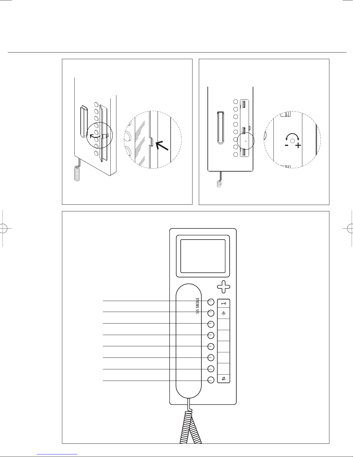
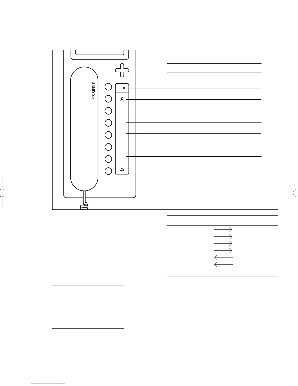
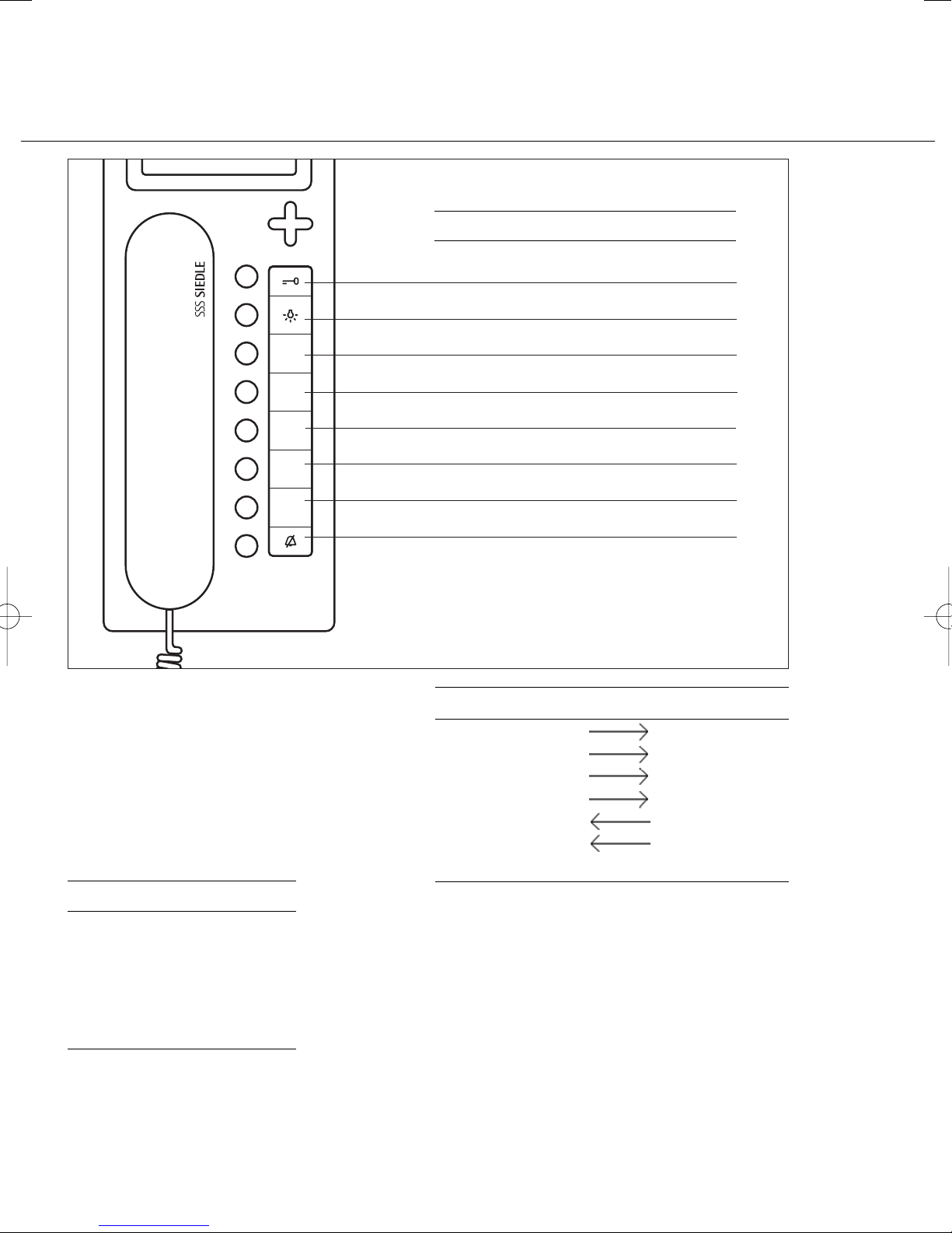
Türöffnertaste
Lichttaste
Taste 1
Taste 2
Taste 3
Taste 4
Taste 5
Taste 6
Türöffnertaste
Door opener
Touche gâche
Deuropenertoets
Lichttaste
Lighting button
Touche lumière
Licht-toets
Taste
Button
Touche
Toets
Page 5
1
3
4
2
Page 6
6
8
7
5
Page 7
9
Page 8
2
10
11
Page 9
3
Deutsch
Montage
Anwendung
Multi-Telefon mit Farbmonitor für
das Siedle-Multi-System, eingebaute
Tasten für Licht- und Türöffner, 6
Tasten frei programmierbar.
Leistungsmerkmale
• Anschluss über Steck-Schraubklemmen für den Bus-Anschluss
6 Adernpaare
• Ruftaste zur Zentrale bzw.
Rufnummer 1
• Mithör- und Mitsehgesperrt
• bis zu 4 Geräte mit gleicher
Rufnummer parallelschaltbar
• In einer Anlage mit den Systemvorgängern HT 740-... mit
MOM/MOC 711-... oder HT 642-...
mit MOM/MOC 611-... einsetzbar
d. h. 100% rückwärtskompatibel in
der Konfiguration 1 bis Konfiguration 3.
Elektrische Spannung
Einbau, Montage und Servicearbeiten elektrischer Geräte
dürfen ausschließlich durch eine
Elektro-Fachkraft erfolgen.
• Die Norm DIN EN 60065 ist
zubeachten! Beim Herstellen der
elektronischen Verbindung sind die
Anforderungen von VDE 0805 bzw.
EN 60950 zubeachten.
• Parallelverlegung zu hochfrequenzführenden oder stark störverseuchten Leitungen sind unbedingt
zu vermeiden.
• Planungs- und Installationsrichtlinien für Multi-Anlagen beachten.
Elektrostatische Aufladung
Durch elektrostatische Aufladung
kann bei direktem Kontakt mit der
Leiterplatte das Gerät zerstört
werden. Vermeiden Sie daher ein
direktes Berühren der Leiterplatte.
Lieferumfang
HTV 840-... bestehend aus
• HTV 840-... (Grundplatte und
Gehäuse mit Leiterplatte), Schriftfeld
und Schrifteinlage
• Hörer
• Federzugschnur
• Blind-Karte für SD-Karteneinschub
• Bedienungsanleitung für den
Endkunden
• diese Produktinformation
Installation
Die Installation kann in jeder beliebigen Form als Parallelverkabelung
erfolgen, empfohlen werden
Stamm- bzw. Steigleitungssysteme
mit Etagenverteilungen. Die Installation der Koaxleitungen erfolgt
sternförmig von der Etagenverteilung.
Reine Stern- oder Ringleitungen
sind zu vermeiden.
Leitungsmaterial
Als Installationsmaterial ist paarig
verdrilltes, abgeschirmtes Kabel
JY(St)Y mit 0,8 mm zu verwenden.
Die Adern 1 und 2 sind in Stammleitungen generell zu verdoppeln,
die Adern der Videoversorgung +Vp
und 0V müssen auch verdoppelt
werden.
Reichweite
Bei 0,8 mm Aderdurchmesser ergibt
sich eine maximale Reichweite von
800 bzw. 1000 m.
Netzversorgung
Die Versorgung der Systemtelefone
erfolgt mit 24 V DC (22-28 V).
Die Versorgungsspannung am Gerät
darf unter Belastung nie unter 22 V
absinken.
Montage
Die Geräte sind standardmäßig für
Wandmontage. Es ist grundsätzlich
eine 55 mm Schalterdose unter der
Kabeleinführung des Systemtelefons
als Klemm- und Stauraum
vorzusehen.
Kabel auf ca. 80 mm abmanteln.
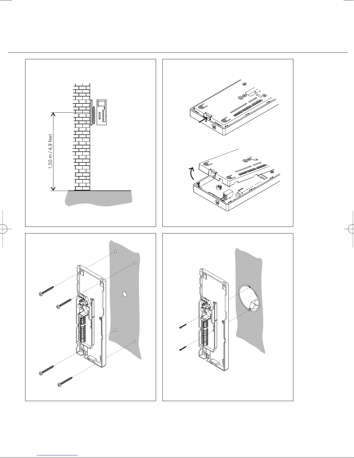
1 Empfohlene Einbauhöhe
ca. 1,50 m bis Gerätemitte.
2 Öffnen des Gerätes von der Rückseite; dazu Rasthebel eindrücken.
3 Bei Montage direkt auf der Wand
die Grundplatte mit 4 Schrauben
befestigen. Einbaulage Oben/Top
beachten.
4 Bei Montage auf Schalterdose
Schraubenöffnungen in der Gerätemitte verwenden. Einbaulage
Oben/Top beachten.
5 Installation nach AS-Plan
vornehmen. Koax-Kabel und
Videoversorgung auf der Leiterplatte
anschließen.
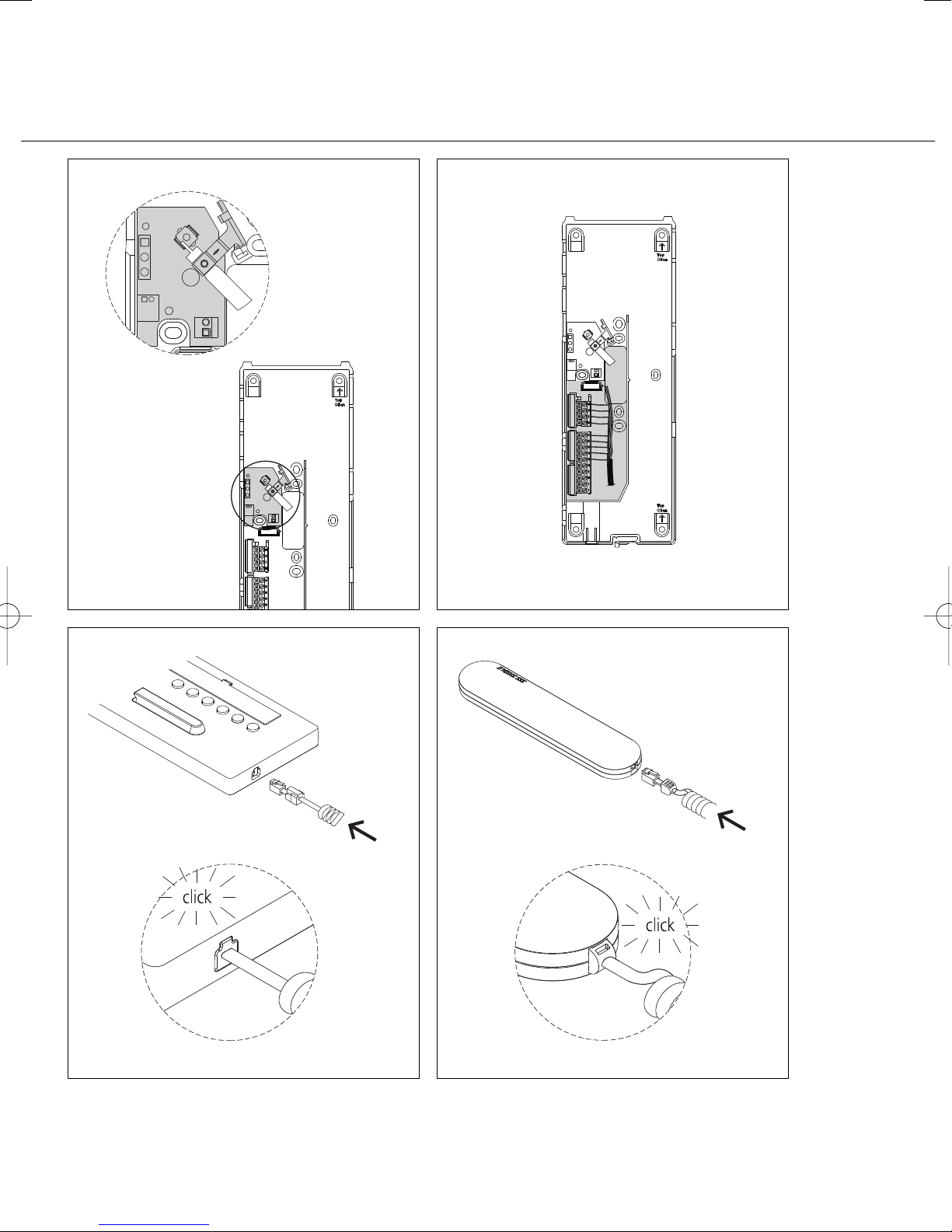
6 Die Adern des Installationskabels
müssen innerhalb des freien Installationsraumes in der Grundplatte
verstaut werden.
7 Farbigen Stecker der Federzugschnur in die Buchse am Gehäuse
einführen, Stecker muss hörbar
einrasten.
8 Anderes Ende der Federzugschnur
in den Hörer einstecken, bis Stecker
einrastet. Die Verbindung ist nicht
mehr lösbar.
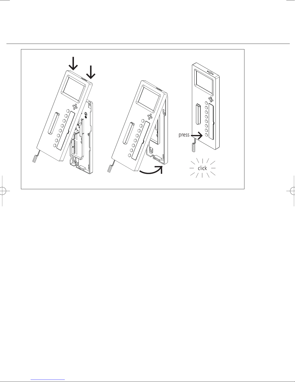
9 Gehäuse oben auf der Grundplatte einhängen und mit leichtem
Druck schließen.
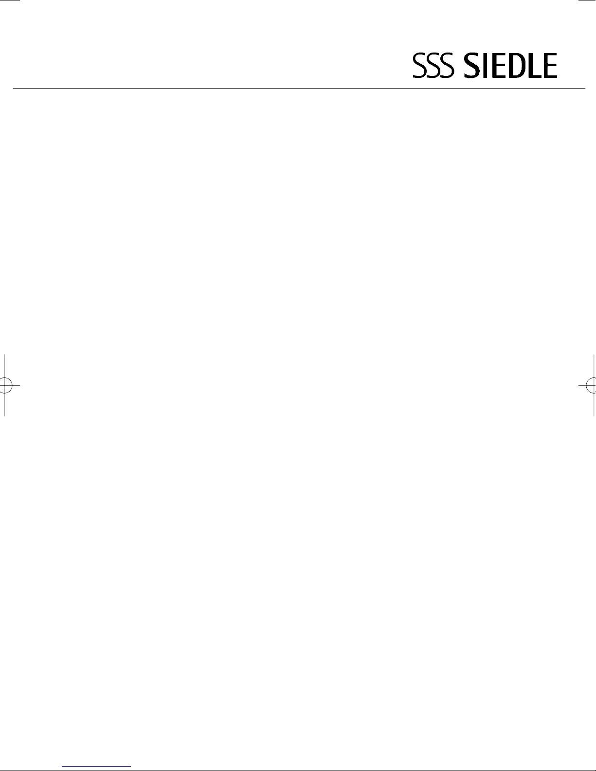
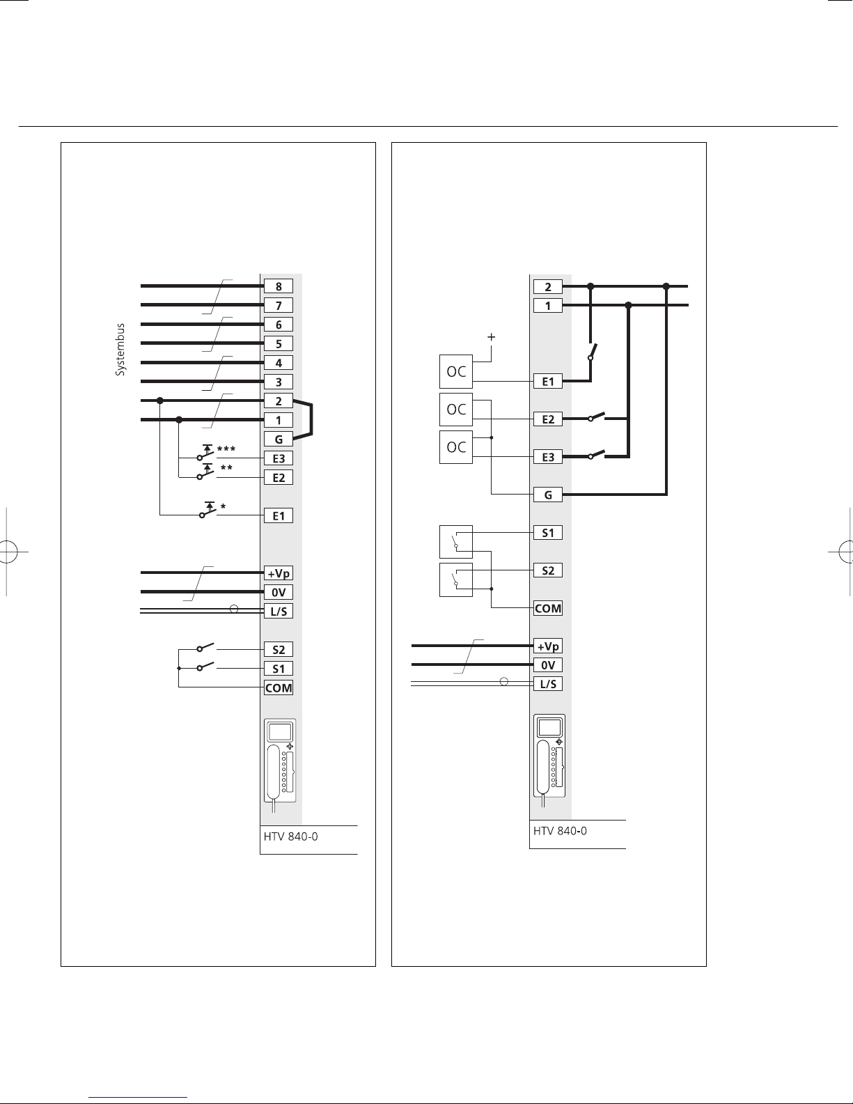
10 Klemmenbelegung
* Etagenruftaste bauseitig
** Alarmtaste/Kontakt bauseitig
*** Taste/Kontakt bauseitig
11 Beschaltung der Ein- und Ausgänge
12 Gegenüberstellung
HT 642-... mit MOM/MOC 611-...,
HT 740-... mit MOM/MOC 711-...
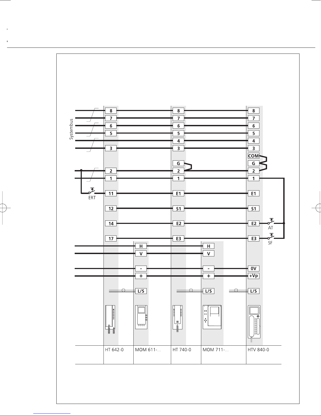
13 Adresseinstellung mit den
Schiebeschaltern.
(Siehe Programmieranleitung)
Demontage
14 Zum Abnehmen des Gehäuses
mit einem Schlitz-Schraubendreher
die Verriegelung nach oben drücken. Leiterplatte und Hörer
verbleiben am Gehäuse-Oberteil.
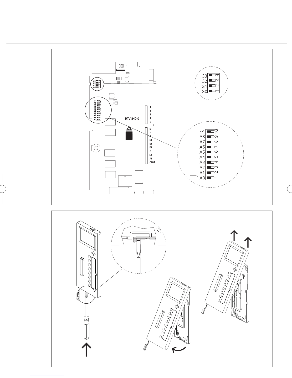
Beschriftung
15 Das Beschriftungsfeld kann mit
den Tastenfunktionen entsprechend
beschriftet werden. Die Sichtscheibe
kann seitlich angehoben werden.
Page 10

4
Einstellung der Ruftonlautstärke
16 Unter der Schrifteinlage ist das
Poti für die Einstellung der Ruftonlautstärke zugänglich.
17 Tastenbelegung des Gerätes.
Zubehör für HTV 840-...
• ZTV 840-... für die Umrüstung von
Wandgerät zu Tischgerät.
Inbetriebnahme
Nach ordnungsgemäßer Montage
und Installation wird
in stromlosen
Zustand
an jedem Gerät eine
Adresse eingestellt (Bild 13,
Einstellung Geräteadresse).
Maximal 4 Geräte können mit der
gleichen Adresse versehen werden,
was bedeutet, dass diese Geräte
dann parallel geschaltet sind.
An zentraler Stelle wird die Anlage
eingeschaltet und nach kurzer Zeit,
max. 3 Minuten ist die Anlage im
Auslieferzustand (Grundkonfiguration 6) betriebsbereit.
Konfiguration festlegen
Im Auslieferzustand ist immer die
Grundkonfiguration 6 festgelegt.
Eine Konfiguration kann nicht
gelöscht sondern nur überschrieben
werden.
In einer Anlage können Geräte
(HTV 840-...) mit unterschiedlichen
Konfigurationen ausgestattet sein.
Dabei orientiert sich der Leistungsumfang der Gesamtanlage immer
an der niedrigsten Konfigurationsstufe.
Der Mischbetrieb ist jedoch nur
zwischen den Konfigurationen 1-3
bzw. 4-6 erlaubt.
Programmier-Schalter-Stellung
Bei manueller Programmierung am
Schiebeschalter den Schalter 10 (FP)
zur Programmierung auf “Ein”
stellen und danach für den Betriebszustand wieder auf “
Aus” stellen.
Ist ein SCO 740-... in der Anlage
integriert, so muss der Schalter
immer auf “Aus” gestellt sein.
Grundkonfiguration
Die 6 festgelegten Grundkonfigurationen können ohne weitere Hilfs-
mittel abgerufen werden.
Bei eingeschaltetem Schiebeschalter
10 (FP) die Licht- und Türöffnertaste
gleich-zeitig drücken, gedrückt
halten und zusätzlich die Ziffer (1-6)
für die gewünschte Konfiguration
drücken.
Nach ca. 3 Sekunden leuchten die
beiden LED’s unter der Türöffnerund Lichttaste kurz auf. Damit ist
die Konfiguration für dieses Gerät
bestätigt. Im Handapparat ertönt
zusätzlich ein Quittungston.
Der Schiebeschalter 10 (FP) muss
nach der Konfiguration wieder
ausgeschaltet werden.
System-Konfiguration
Mit Hilfe der Systemkonfiguration
können alle angeschlossenen
HTV 840-... mit allen Kombinationsmöglichkeiten des Systems individuell konfiguriert werden.
Grundvoraussetzung für die Systemkonfiguration ist immer ein SystemController SCO 740-...
Über ein PRI 602-... kann daran ein
PC angeschlossen werden, der die
Konfiguration erleichtert und über
den die Konfiguration aller Teilnehmer ausgelesen, gespeichert und
ausgedruckt werden kann.
Nähere Angaben hierzu finden Sie in
der Programmieranleitung des
SCO 740-...
Erweiterte Konfiguration
Bei der Erweiterten Konfiguration
erhält der geschulte Fachmann die
Möglichkeit, individuelle Veränderungen in der Konfiguration
vorzunehmen. Hierzu sind jedoch
fundierte Systemkenntnisse zwingend erforderlich.
Bildspeicher
Die Bildspeicherfunktion ist im
Auslieferungszustand deaktiviert.
Sie muss bei Bedarf über die SCOProgrammiersoftware aktiviert
werden. Ausreichende Videospannungsversorgung vorausgesetzt!
Wird ein Bild gespeichert, so wird
dies mit der LED unter der TÖ-Taste
angezeigt.
Die Anzeige kann über die Pro-
grammiersoftware auf jede beliebige
LED gesetzt werden. Außerdem
kann eine beliebige Taste mit der
Funktion "Gespeicherte Bilder
anzeigen” für den Direktzugriff auf
die gespeicherten Bilder belegt
werden. Im Auslieferungszustand
können gespeicherte Bilder mit der
Eingabe-Taste abgerufen werden.
Sind im System Kameras mit
Schwenk/Neige-Funktion vorhanden,
können die Richtungstasten der
Videosteuerung für die S/N-Funktion
benutzt werden.
Bei Auswahl über die Taste
"Steuerung" bleibt das Bild in
Vollgröße stehen und über die
Richtungstasten kann die Kamera
gesteuert werden. Mit der Funktion
"Zurück" steht das Videomodul
wieder im Normalbetrieb.
Nähere Information erhalten Sie
über die Siedle-Multi-Hotline
Telefon +49 7723 63-378
Bildspeicher
Der Bildspeicher des Gerätes ist nur
aktiv, wenn das Multi-Telefon eine
zusätzliche Spannungsversorgung
hat, (Video-Spannungsversorgung
im gesamten System entsprechend
dimensionieren). Er speichert die
jeweils 28 letzten Bilder der Türkamera. Bei Spannungsausfall wird
der Bildspeicher gelöscht.
Der Bildspeicher des Gerätes kann
28 Bilder der Türkamera speichern.
Im Gerät gespeicherte Bilder sind
nach einem Spannungsausfall
gelöscht. Die Funktion des Bildspeichers ist nur aktiv wenn die
Video-Spannungsversorgung im
gesamten System dafür dimensioniert wurde.
Sprache, Datum und Uhrzeit
einstellen
Nach dem ersten Einschalten des
Monitors muss die Sprache ausgewählt werden. Anschließend
wechselt die Anzeige auf die Eingabe von Datum und Uhrzeit. Ist in
der Multi-Anlage eine Systemuhr
Page 11
5
vorhanden, wird die Uhrzeit
automatisch aktualisiert.
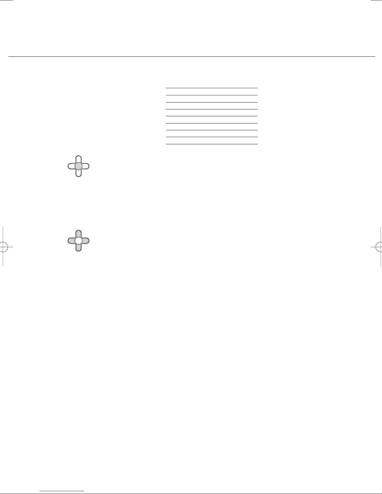
Tastenbelegung Monitor
Die Eingabe erfolgt über die
5-Wege-Taste unter dem Monitor.
Mit der runden Eingabe-Taste in der
Mitte wird der Monitor eingeschaltet oder eine ausgewählte Funktion
bestätigt.
Eingabe-Taste
Mit den Steuer-Tasten rechts, links,
oben und unten findet die Navigation innerhalb der Menüebenen
statt.
Steuer-Tasten
Die Steuer-Tasten können je nach
Anzeige des Monitors mit unterschiedlichen Funktionen belegt sein.
Die Funktion der Tasten ist in der
untersten Zeile des Monitors eingeblendet.
SD-Karte
Auf der Geräteoberseite kann
zusätzlich eine SD-Speicherkarte mit
einer Speicherkapazität von 32 MB
bis 2 GB eingesteckt werden; bei
Auslieferung ist eine Blind-Karte als
Staubschutz eingesteckt.
Die Speicherkarte dient
• zur Erweiterung des
geräteinternen Bildspeichers und
• zur Übertragung der Bilder auf
einen PC mit Hilfe eines
entsprechenden Lesegerätes.
Auf einer SD-Karte können maximal
255 Bilder im Format *.tif mit einer
Auflösung von 640 x 480 Pixel und
einer Dateigröße von ca. 1 MB
gespeichert. Wenn der Speicherplatz
erschöpft oder die maximale Anzahl
von Bildern erreicht ist, wird immer
das älteste Bild überschrieben.
Zum Formatieren der SD-Speicherkarte sollte das Bus-Telefon benutzt
werden; wenn sie am PC formatiert
werden soll, muss das Format
FAT 16 benutzt werden.
Gespeicherte Bilder unterliegen
wie Fotografien dem Urheberrecht.
Zubehör für HTV 840-...
• ZTV 840-... Zubehör-Tisch für die
Umrüstung von Wandgerät zu Tischgerät.
Technische Daten
• Versorgung über Multi-Bus,
Stromaufnahme max. 100 mA
• Stromaufnahme Video max. 70mA
• Klingellautstärke: max. 83 dB (A)
• Farbmonitor 8,8 cm (3,5”)
Bildspeicher:
• 28 Bilder im Gerätespeicher
• SD-Karte von 32 MB bis 2 GB
• max. 255 Bilder auf SD-Karte
möglich
• Dateiformat *.tif
• Datenstruktur FAT 16
• Auflösung 640 x 480 Pixel
• Abmessungen B x H x T
105 x 277 x 45 mm
SD-Karte Anzahl ca. Bilder
32 MB 32
64 MB 64
128 MB 128
256 MB 255
512 MB 255
1 GB 255
2 GB 255
Page 12
6
Display-Anzeige Funktion
Sprache/Language Auswahl der Sprache
Datum/Uhrzeit Automatisch Sommer/Normalzeit
Bildspeicher stellt die Zeit automatisch von
Sommer- auf Normalzeit um.
2005-01-25 21:43:47
Datum und aktuelle Uhrzeit werden
eingestellt.
Einschaltverzögerung Monitor schaltet zeitverzögert ein.
Speicherverzögerung Bild wird zeitverzögert gespeichert.
Ein korrekter Bildaufbau benötigt mindestens
1 Sekunde. Benötigt der Bildaufbau
mehr Zeit, muss der Wert entsprechend höher
eingestellt werden.
Ausschaltverzögerung Monitor schaltet zeitverzögert aus.
Erfolgen keine Eingaben, schaltet sich das
Gerät nach 20 Sekunden aus.
Service V1.00.1.00.00
Anzeige des Softwarestandes.
Zeitsignal empfangen
Information, ob das Zeitsignal DCF77
anliegt.
Testbild weiß
Anzeige weißer Hintergrund
Testbild schwarz
Anzeige schwarzer Hintergrund
Testbild farbig
Anzeige farbiger Hintergrund
Reset
Das Gerät wird neu gestartet. Gespeicherte
Einstellungen wie z. B. Helligkeit oder
Einschaltverzögerung bleiben erhalten.
Bilder, die im Gerät gespeichert sind,
werden gelöscht.
Auslieferungszustand herstellen
Alle Einstellungen werden in den
Auslieferungszustand zurückgesetzt.
Menü-Konfiguration für
die Erst-Inbetriebnahme
Page 13
7
Grundkonfiguration 1
festlegen
Ersatz für HT 441-.../HT 641-...
3 Eingänge,
E2 - E3 10-30 V DC potentialfrei
S1,S2 Kontakt 24 V / 1 A
gem. Fußpunkt
1 Sprechweg
Ruftöne
Freizeichen = Dauer
Besetzt = Einzel kurz
Anruf = Einzel lang
Türruf 1 = Dreiklang langsam
Türruf 2 = Dreiklang schnell
Etagenruf 1 = Zweiklang
Feuer alarm = Alphaton 2
Etagenruf 1
Alarmruf 1
LED 6
Bezugspunkt
Nebensignalgerät
Taste 5
Bezugspunkt
E1 Eingang
E2 Eingang
E3 Eingang
G für E2, E3
S1 Ausgang
S2 Ausgang
COM für S1, S2
Funktion der Anschlussklemmen
Tastenfunktion LED-Anzeige
Türöffner 1 -
Licht (F0) -
ruft Adresse 1 -
Türöffner 2 Rufanzeige blinkend
--
ruft Adresse 1 -
Ausgang 2 -
ruft Adresse 1 Eingang E3
Page 14
8
Grundkonfiguration 2
festlegen
Ersatz für HT 442-.../HT 642-...
3 Eingänge,
E2 - E3 10-30 V DC potentialfrei
S1,S2 Kontakt 24 V / 1 A
gem. Fußpunkt
2 Sprechwege
Ruftöne
Freizeichen = Dauer
Besetzt = Einzel kurz
Anruf = Einzel lang
Türruf 1 = Dreiklang langsam
Türruf 2 = Dreiklang schnell
Etagenruf 1 = Zweiklang
Feuer alarm = Alphaton 2
Etagenruf 1
Alarmruf 1
Personal anwesend
Bezugspunkt
Nebensignalgerät
Monitor EIN
Bezugspunkt
E1 Eingang
E2 Eingang
E3 Eingang
G für E2, E3
S1 Ausgang
S2 Ausgang
COM für S1, S2
Funktion der Anschlussklemmen
Türöffner 1 -
Licht (F0) -
ruft Adresse 1 -
Türöffner 2 Rufanzeige blinkend
Internruf -
ruft Adresse 2 -
ruft Adresse 3 -
Rufabschaltung Rufabschaltung aktiv
Tastenfunktion LED-Anzeige
Page 15

9
Grundkonfiguration 3
festlegen
Ersatz für HT 443-.../HT 643-...
3 Eingänge,
E2 - E3 10-30 V DC potentialfrei
S1,S2 Kontakt 24 V / 1 A
gem. Fußpunkt
2 Sprechwege
Ruftöne
Freizeichen = Dauer
Besetzt = Einzel kurz
Anruf = Einzel lang
Türruf 1 = Dreiklang langsam
Türruf 2 = Dreiklang schnell
Etagenruf 1 = Zweiklang
Feuer alarm = Alphaton 2
Etagenruf 1
Notruf
Anwesenheit
Bezugspunkt
Nebensignalgerät
Beruhigungslampe
Bezugspunkt
E1 Eingang
E2 Eingang
E3 Eingang
G für E2, E3
S1 Ausgang
S2 Ausgang
COM für S1, S2
Funktion der Anschlussklemmen
Türöffner 1 -
Licht (F0) -
ruft Adresse 1 -
Türöffner 2 Rufanzeige blinkend
--
ruft Adresse 2 -
Notruf senden -
Not-Alarmruf 2 löschen Beruhigungslampe
Tastenfunktion LED-Anzeige
Page 16

10
Grundkonfiguration 4
festlegen
Anwendung: Büro
3 Eingänge,
E2 - E3 10-30 V DC potentialfrei
S1,S2 Kontakt 24 V / 1 A
gem. Fußpunkt
2 Sprechwege
Ruftöne
Freizeichen = Dauer
Besetzt = Einzel kurz
Anruf = Einzel lang
Türruf 1 = Dreiklang langsam
Türruf 2 = Dreiklang schnell
Etagenruf 1 = Zweiklang
Feuer alarm = Alphaton 2
Etagenruf 1
Alarmruf 1
Aufmerksamkeitston
Bezugspunkt
Nebensignalgerät
Taste 5
Bezugspunkt
E1 Eingang
E2 Eingang
E3 Eingang
G für E2, E3
S1 Ausgang
S2 Ausgang
COM für S1, S2
Funktion der Anschlussklemmen
Türöffner 1 - -
Licht (F0) - -
ruft Adresse 1 - -
Türmatik Türmatik EIN -
Kamera EIN 1 Min. - -
Internruf - -
Ausgang S2 - -
Rufabschaltung Rufabschaltung Ruf steht an
Tastenfunktion LED leuchtet LED blinkt
Page 17

11
Grundkonfiguration 5
festlegen
Anwendung: Wohnanlage mit
Einzelconciergefunktion
3 Eingänge,
E2 - E3 10-30 V DC potentialfrei
S1,S2 Kontakt 24 V / 1 A
gem. Fußpunkt
2 Sprechwege
Ruftöne
Freizeichen = Dauer
Besetzt = Einzel kurz
Anruf = Einzel lang
Türruf 1 = Dreiklang langsam
Türruf 2 = Dreiklang schnell
Etagenruf 1 = Zweiklang
Feueralarm = Alphaton 2
Etagenruf 1
Alarmruf 1
LED 2
Bezugspunkt
Nebensignalgerät
Taste 5
Bezugspunkt
E1 Eingang
E2 Eingang
E3 Eingang
G für E2, E3
S1 Ausgang
S2 Ausgang
COM für S1, S2
Funktion der Anschlussklemmen
Türöffner 1 - -
Licht (F0) - -
ruft Adresse 1 - -
Einzelconcierge Eingang E3 Einzelconcierge
Kamera EIN 1 Min. - -
Türanschaltung - -
Ausgang S2 - -
Rufabschaltung Rufabschaltung Ruf steht an
Tastenfunktion LED leuchtet LED blinkt
Page 18

12
Grundkonfiguration 6
festlegen
Anwendung: Wohnanlage mit
Rückruffunktion
3 Eingänge,
E2 - E3 10-30 V DC potentialfrei
S1,S2 Kontakt 24 V / 1 A
gem. Fußpunkt
2 Sprechwege
Ruftöne
Freizeichen = Dauer
Besetzt = Einzel kurz
Anruf = Einzel lang
Türruf 1 = Dreiklang langsam
Türruf 2 = Dreiklang schnell
Etagenruf 1 = Zweiklang
Alarmruf 2 = Alphaton 2
Vip-Ruf 1 = Sonderton
Etagenruf 1
Alarmruf 1
Alarmruf 2
Bezugspunkt
Beruhigungslampe
Taste 5
Bezugspunkt
E1 Eingang
E2 Eingang
E3 Eingang
G für E2, E3
S1 Ausgang
S2 Ausgang
COM für S1, S2
Funktion der Anschlussklemmen
Türöffner 1 - -
Licht (F0) - -
ruft Adresse 1 - Rückruf - Rückruf-
Forderung
ruft Adresse 2 - Alamruf 2 --
löschen
Ausgang 2 - -
Rufabschaltung Rufabschaltung Ruf steht an
Tastenfunktion LED leuchtet LED blinkt
Page 19

13
English
Mounting
Application
Multi telephone with colour monitor
for the Siedle Multi system,
integrated buttons for light and
door release, 6 buttons freely
programmable.
Performance features
• Bus connection by means of
plug-in screw terminals
6 pairs of cores
• Call button to the switchboard or
call number 1
• Audio and video privacy device
• Up to 4 devices can be switched in
parallel with the same call number
• Can be used in a system with
system predecessors HT 740-...with
MOM/MOC 711-... or HT 642-...
with MOM/MOC 611-..., i.e. 100%
reverse compatibility in
configuration 1 through to
configuration 3.
Electrical voltage
Mounting, installation and
servicing work on electrical
devices may only be performed
by a suitably qualified
electrician.
• Observe the DIN EN 60065
standard! When establishing the
electronic connection, observe the
requirements of VDE 0805 or
EN 60950.
• Never lay parallel to highfrequency conducting or highly
interference-contaminated cables.
• Observe the planning and
installation guidelines for Multi
systems.
Electrostatic charging
Electrostatic charging can cause
irreparable damage to the circuit
board as a result of direct contact.
For this reason, direct contact with
the circuit board must be avoided.
Scope of supply
HTV 840-... comprising
• HTV 840-... (base plate and
housing with circuit board), lettering
panel and lettering insert
• Receiver
• Spiral cable
• Dummy card for SD card slot
• Operating instructions for the end
user
• This product information
Installation
Installation can be performed in any
optional form as parallel cabling. We
recommend side circuit or rising
mains systems with storey-by-storey
distribution. The coaxial cables are
installed in star formation from the
storey distribution board.
It is advisable to avoid pure star
or ring-main type systems.
Conductor material
Use twisted-pair, shielded cable
JY(St)Y with 0.8 mm cross-section as
installation material.
Cores 1 and 2 must generally be
doubled in side circuits, cores used
for video supply +Vp and 0V must
also be doubled.
Range
With 0.8 mm core diameter, the
maximum range is 800 or 1000 m.
Power supply
The system telephones are supplied
with 24 V DC (22-28 V).
The supply voltage must never be
permitted to drop below 22 V under
load.
Mounting
The devices are intended as
standard for wall mounting. A 55
mm junction box must always be
provided under the system
telephone cable entry as a terminal
and storage space.
Strip back cable to appr. 80 mm.
1 Recommended mounting height
appr. 1.50 m to centre device.
2 Open the device from the back by
pressing in the locking lever.
3 When mounting directly on the
wall, fasten the base plate using
4 screws, paying attention that the
plate is the right way up (top
marking).
4 When mounting on a switch box,
use the screw openings in the
centre of the device, paying
attention that the plate is the right
way up (top marking).
5 Perform the installation in
accordance with the PS diagram.
Connect the coaxial cable and video
supply on the circuit board.
6 The cores of the installation cable
must be stored inside the free
installation space in the base plate.
7 Insert the coloured plug of the
spiral cable into the socket at the
housing. A distinct click is audible
when the plug is correctly inserted.
8 Insert the other end of the spiral
cable into the receiver until the plug
clicks audibly into place. This
connection can no longer be
detached.
9 Slot the housing into the base
plate and close by applying a light
pressure.
10 Terminal assignment
* Existing storey call button
** Existing alarm button/contact
*** Existing button/contact
11 Connection of inputs and
outputs
12 Comparison
HT 642-... with MOM/MOC 611-...,
HT 740-... with MOM/MOC 711-...,
13 Address setting using the sliding
switches.
(See programming instructions)
Dismantling
14 To remove the housing, press the
lock upwards using a flat blade
screwdriver. The circuit board and
receiver remain on the upper part of
the housing.
Lettering
15 The lettering panel can be
inscribed to indicate the button
functions.
The see-through panel
can be lifted at the side.
Page 20

14
Setting the call tone volume
16 The potentiometer for setting
the call tone volume is accessible
under the lettering insert.
17 Assignment of device buttons.
Accessories for HTV 840-...
• ZTV 840-... for conversion from a
wall-mounted to a table-top unit.
Commissioning
Following correct completion of
mounting and installation, the
address is set at each unit while
disconnected from the power
supply
(Fig. 13, setting device
address).
A maximum of 4 devices can be
given the same address, meaning
that these devices are then switched
in parallel.
The system is switched on in a
central location and is then ready
for operation after a short delay in
its as-delivered status (basic
configuration 6).
Define the configuration
In the as-delivered status, basic
configuration 6 is always defined. A
configuration cannot be deleted but
only overwritten.
Devices (HTV 840-...) can be given
different configurations within one
system. In this case, the
performance scope of the entire
system is always oriented to the
lowest configuration stage.
However, mixed operation is only
admissible between configurations
1-3 & 4-6.
Programming switch setting
When performing manual
programming at the sliding switch,
set switch 10 (FP) for programming
to “ON” and then for the operating
status back to “
OFF”.
If an SCO 740-... is integrated in the
system, the switch must always be
set to “OFF”.
Basic configuration
The 6 defined basic configurations
can be accessed without any
additional aids. With the sliding
switch 10 (FP) switched on press the
light and door release button
simultaneously, hold down and
additionally press the numbers (1-6)
for the required configuration.
After appr. 3 seconds, the two LEDs
under the door release and light
button briefly light up. The
configuration for this device is now
confirmed. An acknowledgement
tone also sounds in the handset.
The sliding switch 10 (FP) must
be switched off again after
configuration.
System configuration
With the aid of the system
configuration, all connected
HTV 840-... units can be configured
with all the system's configuration
possibilities. The basic requirement
for system configuration is always a
system controller SCO 740-...
Through a PRI 602-... it is possible to
connect a PC which simplifies the
configuration process. This allows
the configuration of all users to be
read out, saved and printed.
For more details, see the
programming instructions for the
SCO 740-...
Extended configuration
In the extended configuration,
suitably trained specialists have the
opportunity to carry out individual
changes in the configuration.
However, a thorough understanding
and knowledge of the system are
mandatory for this.
Video memory
The picture save function is
deactivated in the as-delivered
status. If required, it has to be
activated using the SCO
programming software. This
function is only possible provided a
sufficient video power supply is
available!
If a picture is saved, this is indicated
by the LED underneath the DR
button.
The display can be set using the
programming software to any
optional LED. In addition, an
optional button can be assigned the
function "Display saved pictures”
for direct access to the saved picture
library. In the as-delivered status,
saved pictures can be accessed using
the Enter button.
If the system includes cameras with
a swivel and tilt function, the
direction buttons of the video
control system can be used to
actuate the swivel and tilt
movements.
When selected using the "Control"
button, the picture remains full size
on the screen and the camera can
be controlled using the direction
buttons. Using the "Back"
function, the video module is
returned to normal mode.
For more detailed information,
contact the Siedle-Multi hotline
Tel. +49 7723 63-378
Video memory
The device's video memory is only
active if the Multi telephone has an
additional power supply (dimension
the video power supply accordingly
in the whole system). It stores the
last 28 pictures taken by the door
camera. In the event of a power
failure, the video memory is deleted.
The device's video memory is able to
save 28 pictures from the door
camera.
Pictures saved in the device are
erased after a power failure. The
video memory is only functional
when the video supply voltage has
been dimensioned accordingly
throughout the whole system.
Setting the language, date and
time
After first switching on the monitor,
the language must be selected. The
display then changes over to the
input of date and time. If there is a
system clock available in the Multi
system, the time is automatically
updated.
Page 21

Saved pictures are subject to the
same copyright restrictions as
photographs.
Accessories for HTV 840-...
• ZTV 840-... table-top accessory for
conversion from a wall-mounted to
a table-top device.
Specifications
• Supply via Multi bus, current
consumption max. 100 mA
• Current consumption video max.
70 mA
• Ring tone volume: max. 83 dB (A)
• Colour monitor 8.8 cm (3.5”)
Video memory:
• 28 pictures in the device's own
internal memory
• SD card from 32 MB to 2 GB
• max. 255 pictures can be stored
on the SD card
• File format *.tif
• Data structure FAT 16
• Resolution 640 x 480 Pixel
• Dimensions W x H x D
105 x 277 x 45 mm
Assigning the monitor buttons
Entries are made using the 5-way
button under the monitor.
Using the round Enter button in the
middle, the monitor is switched on
or a selected function confirmed.
Enter button
Using the control buttons on the
right, left, top and bottom, it is
possible to navigate within the
menu levels.
Control buttons
The control buttons can be assigned
with different functions depending
on the monitor display. The
functions of the buttons are
indicated by a display superimposed
at the bottom edge of the monitor.
SD card
At the top of the device, an SD
memory card can additionally be
inserted to increase the memory
capacity from 32 MB to 2 GB; On
delivery, a dummy card is inserted in
the slot to act as a dust protection.
The memory card is used
• to extend the unit's internal video
memory and
• to transmit the pictures to a PC
with the aid of the relevant reading
unit.
On the SD card, a maximum of 255
pictures in *.tif format can be stored
with a resolution of 640 x 480 pixel
and a file size of appr. 1 MB. When
the memory capacity is exhausted,
or the maximum number of pictures
has been saved, the oldest picture is
overwritten every time a new one is
taken.
The bus telephone should be used
to format the SD card; If you wish
to format at the PC, the FAT 16
format should be used.
15
SD card appr. no of
pictures
32 MB 32
64 MB 64
128 MB 128
256 MB 255
512 MB 255
1 GB 255
2 GB 255
Page 22

16
Display Function
Sprache/Language Language selection
Date/time Automatic summer/normal time
Video memory automatically resets the time
from summer to normal time.
2005-01-25 21:43:47
The date and current time are set.
ON delay The monitor switches on with a time delay.
Save delay The picture is saved with a time delay.
It takes at least 1 second to generate a correct
picture structure. If picture generation takes
longer, the value setting must be increased
accordingly.
OFF delay The monitor switches off with a time delay.
If nothing is entered, the device switches off
after 20 seconds.
Servicing V1.00.1.00.00
Display of the software status.
Time signal received
Indication of whether the time signal DCF77
has been received.
Test picture white
Display white background.
Test picture black
Display black background.
Test picture coloured
Display colour background.
Reset
The device is restarted. Saved settings such as
brightness or ON delay are retained.
Pictures saved in the device are erased.
Restoring the as-delivered status
All settings are reset to the as-delivered status.
Menu configuration for
initial commissioning
Page 23

17
Define basic
configuration 1
Replacement for
HT 441-.../ HT 641-...
3 inputs,
E2 - E3 10-30 V DC potential-free
S1,S2 contact 24 V / 1 A
As per foot point
1 speech channel
Call tones
Call
connected = Continuous
Engaged = Single short
Call = Single long
Door call 1 = Threetone slow
Door call 2 = Threetone fast
Storey call 1 = Two-tone
Fire alarm = Alpha tone 2
Storey call 1
Alarm call 1
LED 6
Reference point
Secondary signal unit
Button 5
Reference point
E1 Input
E2 Input
E3 Input
G for E2, E3
S1 Output
S2 Output
COM for S1, S2
Function of the connecting terminals
Button function LED display
Door release 1 -
Light (F0) -
Calls address 1 -
Door release 2 Call display flashing
--
Calls address 1 -
Output 2 -
Calls address 1 Input E3
Page 24

18
Define basic
configuration 2
Replacement for
HT 442-.../HT 642-...
3 inputs,
E2 - E3 10-30 V DC potential-free
S1,S2 contact 24 V / 1 A
As per foot point
2 speech channels
Call tones
Call
connected = Continuous
Engaged = Single short
Call = Single long
Door call 1 = Threetone slow
Door call 2 = Threetone fast
Storey call 1 = Two-tone
Fire alarm = Alpha tone 2
Storey call 1
Alarm call 1
Personnel present
Reference point
Secondary signal unit
Monitor ON
Reference point
E1 Input
E2 Input
E3 Input
G for E2, E3
S1 Output
S2 Output
COM for S1, S2
Function of the connecting terminals
Door release 1 -
Light (F0) -
Calls address 1 -
Door release 2 Call display flashing
Internal call -
Calls address 2 -
Calls address 3 -
Call silencing Call silencing active
Button function LED display
Page 25

19
Define basic
configuration 3
Replacement for
HT 443-.../HT 643-...
3 inputs,
E2 - E3 10-30 V DC potential-free
S1,S2 contact 24 V / 1 A
As per foot point
2 speech channels
Call tones
Call
connected = Continuous
Engaged = Single short
Call = Single long
Door call 1 = Threetone slow
Door call 2 = Threetone fast
Storey call 1 = Two-tone
Fire alarm = Alpha tone 2
Storey call 1
Emergency call
Presence
Reference point
Secondary signal unit
Reassurance lamp
Reference point
E1 Input
E2 Input
E3 Input
G for E2, E3
S1 Output
S2 Output
COM for S1, S2
Function of the connecting terminals
Door release 1 -
Light (F0) -
Calls address 1 -
Door release 2 Call display flashing
- -
Calls address 2 -
Send emergency call Delete emergency Reassurance lamp
alarm call 2
Button function LED display
Page 26

20
Define basic
configuration 4
Application: Office
3 inputs,
E2 - E3 10-30 V DC potential-free
S1,S2 contact 24 V / 1 A
As per foot point
2 speech channels
Call tones
Call
connected = Continuous
Engaged = Single short
Call = Single long
Door call 1 = Threetone slow
Door call 2 = Threetone fast
Storey call 1 = Two-tone
Fire alarm = Alpha tone 2
Storey call 1
Alarm call 1
Attention tone
Reference point
Secondary signal unit
Button 5
Reference point
E1 Input
E2 Input
E3 Input
G for E2, E3
S1 Output
S2 Output
COM for S1, S2
Function of the connecting terminals
Door release 1 -
Light (F0) -
Calls address 1 -
Doormatic Doormatic ON -
Camera ON 1 Min. - -
Internal call -
Output S2
Call silencing Call silencing Call waiting
Button function LED alight LED flashing
Page 27

21
Define basic
configuration 5
Application: Apartment complex
with individual concierge
function
3 inputs,
E2 - E3 10-30 V DC potential-free
S1,S2 contact 24 V / 1 A
As per foot point
2 speech channels
Call tones
Call
connected = Continuous
Engaged = Single short
Call = Single long
Door call 1 = Threetone slow
Door call 2 = Threetone fast
Storey call 1 = Two-tone
Fire alarm = Alpha tone 2
Storey call 1
Alarm call 1
LED 2
Reference point
Secondary signal unit
Button 5
Reference point
E1 Input
E2 Input
E3 Input
G for E2, E3
S1 Output
S2 Output
COM for S1, S2
Function of the connecting terminals
Door release 1 -
Light (F0) -
Calls address 1 -
Single concierge Input E3 Single concierge
Camera ON 1 Min. - -
Door actuation - -
Output S2
Call silencing Call silencing Call waiting
Button function LED alight LED flashing
Page 28

22
Define basic
configuration 6
Application: Apartment complex
with callback function
3 inputs,
E2 - E3 10-30 V DC potential-free
S1,S2 contact 24 V / 1 A
As per foot point
2 speech channels
Call tones
Call
connected = Continuous
Engaged = Single short
Call = Single long
Door call 1 = Threetone slow
Door call 2 = Threetone fast
Storey call 1 = Two-tone
Alarm call 2 = Alpha tone 2
VIP call 1 = Special tone
Storey call 1
Alarm call 1
Alarm call 2
Reference point
Reassurance lamp
Button 5
Reference point
E1 Input
E2 Input
E3 Input
G for E2, E3
S1 Output
S2 Output
COM for S1, S2
Function of the connecting terminals
Door release 1 -
Light (F0) -
Calls address 1 Callback - Callback-
request
Calls address 2 alarm call 2 --
delete
Output 2 -
Call silencing Call silencing Call waiting
Button function LED alight LED flashing
Page 29

23
Français
Montage
Application
Téléphone Multi avec moniteur
couleur pour le système Siedle-
Multi, touches incorporées pour
lumière et gâche, 6 touches
librement programmables.
Caractéristiques fonctionnelles
• Raccordement par l'intermédiaire
de bornes à vis enfichables pour le
raccordement bus 6 paires de fils
• Touche d'appel vers la centrale ou
numéro d'appel 1
• Secret d'écoute et secret de vision
• Jusqu'à 4 appareils peuvent être
commutés en parallèle avec le
même numéro d'appel
• Utilisable dans une installation
composée des systèmes prédé-
cesseurs HT 740-...avec MOM/
MOC 711-... ou HT 642-... avec
MOM/MOC 611-..., c'est-à-dire
100% rétrocompatible dans la
configuration 1 et jusqu'à la
configuration 3.
Tension électrique
L'installation, le montage et
l'entretien d'appareils électriques
ne doivent être réalisés que par
un spécialiste en électricité.
• La norme DIN EN 60065 doit être
respectée ! Lors de l'établissement
de la liaison électronique, les
exigences de VDE (Fédération des
Electrotechniciens Allemands) 0805
ou EN 60950 doivent être
respectées.
• Une pose parallèlement à des
lignes conductrices de haute
fréquence ou fortement pertur-
batrices doit impérativement être
évitée.
• Respecter les directives de plani-
fication et d'installation des
installations Multi.
Charge électrostatique
La charge électrostatique peut
détruire l'appareil en cas de contact
direct avec la carte de circuits
imprimés. Evitez par conséquent
tout contact direct avec la carte de
circuits imprimés.
Etendue de la fourniture
HTV 840-... composé de :
• HTV 840-... (Socle et boîtier avec
carte de circuits imprimés), zone de
marquage et insert de marquage
• Combiné
• Cordon spiralé
• Fausse-carte pour enfichage de la
carte SD
• Notice d'utilisation pour le
consommateur
• La présente information produit
Installation
L'installation peut être effectuée
sous n'importe quelle forme, en tant
que câblage parallèle, des systèmes
de base ou à ligne ascendante avec
distributions en étages étant
conseillés. L'installation des lignes
coaxiales s'effectue en étoile à partir
de la distribution d'étage.
Les lignes en étoile ou annulaires
pures sont à éviter.
Câbles
Il faut utiliser, comme matériel
d'installation, un câble appairé
torsadé et blindé JY(St)Y de 0,8 mm.
Les fils 1 et 2 doivent en général
être doublés dans les lignes de base,
et les fils de l'alimentation vidéo
+Vp et 0V doivent également être
doublés.
Portée
Avec un diamètre de fil de 0,8 mm,
on obtient une portée maximum de
800 ou 1000 m.
Alimentation secteur
L'alimentation des téléphones
systèmes s'effectue en 24 V CC
(22-28 V).
La tension d'alimentation sur
l'appareil ne doit jamais, sous
charge, chuter au-dessous de 22 V.
Montage
De série, les appareils sont prévus
pour un montage mural. Il faut en
principe prévoir une prise de 55 mm
sous le passage de câble du
téléphone système, en tant que
zone de blocage et de rangement.
Dénuder le câble sur 80 mm
environ.
1 Hauteur de montage conseillée
env. 1,50 m du centre de l'appareil.
2 Ouverture de l'appareil par la face
arrière ; à ces fins, appuyer sur le
levier encliquetable.
3 Dans le cas d'un montage
directement au mur, fixer le socle à
l'aide de 4 vis. Respecter la position
de montage Haut/Top.
4 Dans le cas d'un montage sur
prise, utiliser les orifices pour vis
prévus au centre de l'appareil.
Respecter la position de montage
Haut/Top.
5 Effectuer l'installation
conformément au schéma AS.
Raccorder le câble coaxial et
l'alimentation vidéo sur la carte de
circuits imprimés.
6 Les fils du câble d'installation
doivent être regroupés dans la zone
d'installation libre du socle.
7 Introduire la prise mâle de couleur
du cordon spiralé dans la prise
femelle du boîtier, un clic devant
être perçu lorsque la prise mâle
s'emboîte.
8 Emboîter l'autre extrémité du
cordon spiralé dans le combiné,
jusqu'à l'encliquetage de la prise
mâle. Le raccordement ne peut plus
être défait.
9 Accrocher le boîtier en haut du
socle et fermer en exerçant une
légère pression.
10 Implantation des bornes
* Touche d'appel d'étage à
prévoir par le client
** Touche d'alarme/contact à
prévoir par le client
*** Touche/contact à prévoir par le
client
Page 30

24
11 Câblage des entrées et des
sorties
12 Comparaison
HT 642-... avec MOM/MOC 611-...,
HT 740-... avec MOM/MOC 711-...
13 Réglage de l'adresse avec les
commutateurs à coulisse.
(Voir notice de programmation)
Démontage
14 Pour déposer le boîtier à l'aide
d'un tournevis pour vis à tête
fendue, repousser le verrouillage
vers le haut. La carte de circuits
imprimés et le combiné restent sur
la partie supérieure du boîtier.
Marquage
15 Les fonctions des touches
peuvent être marquées en conséquence sur la zone de marquage. La
vitre peut être relevée latéralement.
Réglage du volume de la tonalité
d'appel
16 Sous l'insert de marquage, on
peut accéder au potentiomètre
destiné au réglage du volume de la
tonalité d'appel.
17 Affectation des touches de
l'appareil
.
Accessoire pour HTV 840-...
• ZTV 840-... pour transformer un
appareil mural en un appareil de
table.
Mise en service
Une fois que le montage et
l'installation ont été correctement
effectués, on règle une adresse sur
chaque appareil,
à l'état hors
tension
(figure 13, réglage adresse
appareil).
4 appareils au maximum peuvent
avoir la même adresse, ce qui
signifie que ces appareils sont alors
commutés en parallèle.
Au poste central, on met
l'installation en marche et, au bout
de peu de temps, max. 3 minutes,
l'installation est prête à fonctionner
à l'état à la livraison (configuration
de base 6).
Définir la configuration
A l'état à la livraison, c'est toujours
la configuration de base 6 qui est
définie. Une configuration ne peut
pas être effacée, elle peut seulement
être écrasée.
Une installation peut être équipée
d'appareils (HTV 840-...) ayant des
configurations différentes. Les
capacités de l'ensemble de
l'installation s'orientent alors
toujours sur le niveau de
configuration le plus bas.
L'utilisation mixte n'est toutefois
autorisée qu'entre les configurations
1-3 ou 4-6.
Position du commutateur de
programmation
En programmation manuelle sur le
commutateur à coulisse, positionner
le commutateur 10 (FP), destiné à la
programmation, sur “Marche”, puis
le remettre sur “
Arrêt” pour l'état
de fonctionnement.
Si un SCO 740-... est intégré à
l'installation, le commutateur doit
toujours être positionné sur “Arrêt”.
Configuration de base
Les 6 configurations de base
définies peuvent être appelées sans
autres moyens auxiliaires. Le
commutateur à coulisse 10 (FP)
étant positionné sur Marche,
appuyer en même temps sur la
touche lumière et la touche gâche,
maintenir l'appui et appuyer sur le
chiffre (1-6) correspondant à la
configuration souhaitée.
Au bout de 3 secondes environ, les
deux LED se trouvant sous la touche
gâche et la touche lumière
s'éclairent pendant une brève
période. Ceci valide la configuration
de cet appareil. Dans l'appareil
manuel, une tonalité d'acquittement
retentit également.
Après la configuration, le
commutateur à coulisse 10 (FP)
doit être repositionné sur Arrêt.
Configuration du système
La configuration du système permet
de configurer individuellement tous
les HTV 840-... raccordés, avec
toutes les possibilités de
configuration du système. La
condition de base nécessaire à la
configuration du système est
toujours un contrôleur système
SCO 740-...
Par l'intermédiaire d'une PRI 602-...,
on peut y raccorder un PC qui
facilite la configuration et par
l'intermédiaire duquel on peut lire,
mémoriser et imprimer la
configuration de tous les abonnés.
Vous trouverez de plus amples
indications à cet égard dans la
notice de programmation du
SCO 740-...
Configuration élargie
La configuration élargie donne au
spécialiste formé la possibilité de
procéder à des modifications
individuelles de la configuration.
Ceci nécessite toutefois, impérativement, de solides connaissances
du système.
Mémoire d'images
La fonction mémoire d'images est
désactivée au moment de la
livraison. Elle doit être activée, en
cas de besoin, par l'intermédiaire du
logiciel de programmation SCO.
La condition à remplir est une
alimentation en tension vidéo
suffisante!
Lorsque l'on mémorise une image,
ceci est indiqué par la LED se
trouvant sous la touche TÖ (gâche).
L'affichage peut être placé sur
n'importe quelle LED, par l'intermédiaire du logiciel de programmation.
Par ailleurs, n'importe quelle touche
peut être affectée de la fonction
"Afficher images mémorisées", pour
un accès direct aux images mémorisées. A l'état à la livraison, les
images mémorisées peuvent être
appelées à l'aide de la touche
Entrée.
Si le système comporte des caméras
dotées de la fonction pivotement/
inclinaison, les touches de direction
de la commande vidéo peuvent être
utilisées pour la fonction N/B.
Lors d'une sélection par l'intermédiaire de la touche "Commande",
l'image demeure dans sa pleine
taille et la caméra peut être pilotée
Page 31

25
par l'intermédiaire des touches de
direction. Avec la fonction "Retour",
le module vidéo est de nouveau en
mode normal.
Vous obtiendrez de plus amples
informations par l'intermédiaire
de la Hotline Siedle-Multi
Téléphone +49 7723 63-378
Mémoire d'images
La mémoire d'images de l'appareil
n'est active que si le téléphone Multi
comporte une alimentation en
tension complémentaire). Elle
mémorise les 28 dernières images
de la caméra de porte. En cas de
panne de secteur, la mémoire
d'images s'efface.
La mémoire d'images de l'appareil
peut mémoriser 28 images de la
caméra de porte.
Les images mémorisées dans
l'appareil sont effacées après une
panne de courant. La fonction de la
mémoire d'images n'est active que
si l'alimentation en tension vidéo a
été dimensionnée à ces fins dans
l'ensemble du système.
Réglage de la langue, de la date
et de l'heure
Après la première mise en marche
du moniteur, il faut choisir la
langue. L'afficheur passe ensuite à
l'entrée de la date et de l'heure. Si
l'installation Multi comporte une
horloge système, l'heure se met
automatiquement à jour.
Affectation des touches
moniteur
L'entrée s'effectue par l'intermédiaire de la touche à 5 voies se
trouvant sous le moniteur.
La touche d'entrée ronde, qui se
trouve au centre, permet de mettre
le moniteur en marche ou de valider
une fonction sélectionnée.
Touche d'entrée
Les touches de commande à droite,
à gauche, en haut et en bas
permettent de naviguer dans les
différents niveaux de menu.
Touches de commande
Différentes fonctions peuvent être
affectées aux touches de
commande, en fonction de
l'affichage du moniteur. La fonction
des touches s'affiche sur la ligne se
trouvant tout en bas du moniteur.
Carte SD
En haut de l'appareil, il est possible
d'ajouter une carte mémoire SD
d'une capacité mémoire de 32 MB
à 2 GB; au moment de sa livraison,
l'appareil est équipé d'une faussecarte destinée à assurer sa
protection contre la poussière.
La carte mémoire sert
• à augmenter la mémoire d'images
interne à l'appareil et
• à transmettre les images à un PC à
l'aide d'un lecteur correspondant.
Une carte SD permet de mémoriser
jusqu'à 255 images au format *.tif à
une résolution de 640 x 480 pixels
et dans une taille de fichier de 1 MB
environ. Lorsque l'emplacement
mémoire est épuisé ou que le
nombre maximum d'images est
atteint, c'est toujours l'image la plus
ancienne qui est écrasée.
Pour formater la carte mémoire SD,
il faut utiliser le téléphone bus; s'il
s'agit de la formater sur le PC, il
faut utiliser le format FAT 16.
Les images en mémoire sont
soumises, de la même façon que
les photographies, aux droits
d'auteur.
Accessoire pour HTV 840-...
• ZTV 840-... Accessoire table pour
transformer un appareil mural en
un appareil de table.
Caractéristiques techniques :
• Alimentation par l'intermédiaire
du bus Multi, intensité absorbée
max. 100 mA
• Intensité absorbée vidéo max.
70 mA
• Volume de la sonnerie :
max. 83 dB (A)
• Moniteur couleur 8,8 cm (3,5”)
Mémoire d'images :
• 28 images dans la mémoire de
l'appareil
• Carte SD de 32 MB à 2 GB
• Max. 255 images possibles sur la
carte SD
• Format des fichiers *.tif
• Structure des données FAT 16
• Résolution 640 x 480 pixels
• Dimensions L x H x P
105 x 277 x 45 mm
Carte SD,
Nombre
d'images, environ
32 MB 32
64 MB 64
128 MB 128
256 MB 255
512 MB 255
1 GB 255
2 GB 255
Page 32

26
Affichage Fonction
Langue/Language Choix de la langue
Date/heure Réglage automatique de l'heure
d'été/l'heure normale
La mémoire d'image passe automatiquement
de l'heure d'été à l'heure normale.
2005-01-25 21:43:47
Réglage de la date et de l'heure actuelle.
Temporisation Le moniteur se met en marche d'une façon
de démarrage temporisée.
Temporisation L'image se mémorise d'une façon temporisée.
de la mémoire Une constitution correcte de l'image demande
au moins 1 seconde. Si la constitution de
l'image demande plus de temps, il faut régler
en conséquence une valeur plus grande.
Temporisation d'arrêt Le moniteur s'arrête d'une façon temporisée.
Si l'on n'effectue pas d'entrées, l'appareil
s'arrête au bout de 20 secondes.
Dépannage V1.00.1.00.00
Affichage du niveau du logiciel.
Recevoir signal temps
Information indiquant si le signal temps DCF77
est présent.
Image test en blanc
Affichage fond blanc
Image test en noir
Affichage fond noir.
Image test en couleur
Affichage fond en couleur.
Reset
On redémarre l'appareil. Les réglages
mémorisés comme, p. ex., la luminosité ou la
temporisation de mise en marche, demeurent.
Les images qui sont mémorisées dans
l'appareil s'effacent.
Etablir l'état à la livraison
Tous les réglages sont ramenés à l'état à la
livraison.
Configuration du menu pour
la première mise en service
Page 33

27
Définir la configuration
de base 1
Remplace HT 441-.../HT 641-...
3 entrées,
E2 - E3 10-30 V CC sans potentiel
S1,S2 Contact 24 V / 1 A
selon base
1 voie de communication
Tonalités d'appel
Libre = Permanente
Occupé = Individuelle courte
Appel = Individuelle longue
Appel de
porte 1 = Trois sons lents
Appel de
porte 2 = Trois sons rapides
Appel
d'étage 1 = Deux sons
Alarme
incendie = Tonalité alpha 2
Appel d'étage 1
Appel d'alarme 1
LED 6
Point de référence
Appareil de sign. aux.
Touche 5
Point de référence
E1 Entrée
E2 Entrée
E3 Entrée
G pour E2, E3
S1 Sortie
S2 Sortie
COM pour S1, S2
Fonction des bornes de raccordement
Fonction des touches Affichage LED
Gâche 1 -
Lumière (F0) -
Appelle l'adresse 1 -
Gâche 2
Affichage d'appel clignotant
--
Appelle l'adresse 1 -
Sortie 2 -
Appelle l'adresse 1 Entrée E3
Page 34

28
Définir la configuration
de base 2
Remplace HT 442-.../HT 642-...
3 entrées,
E2 - E3 10-30 V CC sans potentiel
S1,S2 Contact 24 V / 1 A
selon base
2 voies de communication
Tonalités d'appel
Libre = Permanente
Occupé = Individuelle courte
Appel = Individuelle longue
Appel de
porte 1 = Trois sons lents
Appel de
porte 2 = Trois sons rapides
Appel
d'étage 1 = Deux sons
Alarme
incendie = Tonalité alpha 2
Appel d'étage 1
Appel d'alarme 1
Personnel présent
Point de référence
Appareil de sign. aux.
MARCHE moniteur
Point de référence
E1 Entrée
E2 Entrée
E3 Entrée
G pour E2, E3
S1 Sortie
S2 Sortie
COM pour S1, S2
Fonction des bornes de raccordement
Gâche 1 -
Lumière (F0) -
Appelle l'adresse 1 Gâche 2 Affichage d'appel
clignotant
Appel interne -
Appelle l'adresse 2 -
Appelle l'adresse 3 Désactivation de Désactivation de
la sonnerie d'appel la sonnerie d'appel active
Fonction des touches Affichage LED
Page 35

29
Définir la configuration
de base 3
Remplace HT 443-.../HT 643-...
3 entrées,
E2 - E3 10-30 V CC sans potentiel
S1,S2 Contact 24 V / 1 A
selon base
2 voies de communication
Tonalités d'appel
Libre = Permanente
Occupé = Individuelle courte
Appel = Individuelle longue
Appel de
porte 1 = Trois sons lents
Appel de
porte 2 = Trois sons rapides
Appel
d'étage 1 = Deux sons
Alarme
incendie = Tonalité alpha 2
Appel d'étage 1
Appel au secours
Présence
Point de référence
Appareil de sign. aux.
Lampe tranquillisante
Point de référence
E1 Entrée
E2 Entrée
E3 Entrée
G pour E2, E3
S1 Sortie
S2 Sortie
COM pour S1, S2
Fonction des bornes de raccordement
Gâche 1 -
Lumière (F0) -
Appelle l'adresse 1 Gâche 2 Affichage d'appel
clignotant
--
Appelle l'adresse 2 -
Envoyer appel au secours Effacer appel alarme
secours 2 Lampe tranquillisante
Fonction des touches Affichage LED
Page 36

30
Définir la configuration
de base 4
Application : Bureau
3 entrées,
E2 - E3 10-30 V CC sans potentiel
S1,S2 Contact 24 V / 1 A
selon base
2 voies de communication
Tonalités d'appel
Libre = Permanente
Occupé = Individuelle courte
Appel = Individuelle longue
Appel de
porte 1 = Trois sons lents
Appel de
porte 2 = Trois sons rapides
Appel
d'étage 1 = Deux sons
Alarme
incendie = Tonalité alpha 2
Appel d'étage 1
Appel d'alarme 1
Tonalité pour attirer l'attention
Point de référence
Appareil de sign. aux.
Touche 5
Point de référence
E1 Entrée
E2 Entrée
E3 Entrée
G pour E2, E3
S1 Sortie
S2 Sortie
COM pour S1, S2
Fonction des bornes de raccordement
Gâche 1 - -
Lumière (F0) - -
Appelle l'adresse 1 - Ouverture automatique Ouverture auto. des
des portes portes en MARCHE -
Caméra en
MARCHE 1 mn - -
Appel interne - -
Sortie S2 - Désactivation de la Désactivation de la Appel en attente
sonnerie d'appel sonnerie d'appel
Fonction des touches LED allumée LED clignotante
Page 37

31
Définir la configuration
de base 5
Application : Complexe
résidentiel avec fonction
concierge individuelle
3 entrées,
E2 - E3 10-30 V CC sans potentiel
S1,S2 Contact 24 V / 1 A
selon base
2 voies de communication
Tonalités d'appel
Libre = Permanente
Occupé = Individuelle courte
Appel = Individuelle longue
Appel de
porte 1 = Trois sons lents
Appel de
porte 2 = Trois sons rapides
Appel
d'étage 1 = Deux sons
Alarme
incendie = Tonalité alpha 2
Appel d'étage 1
Appel d'alarme 1
LED 2
Point de référence
Appareil de sign. aux.
Touche 5
Point de référence
E1 Entrée
E2 Entrée
E3 Entrée
G pour E2, E3
S1 Sortie
S2 Sortie
COM pour S1, S2
Fonction des bornes de raccordement
Gâche 1 - -
Lumière (F0) - -
Appelle l'adresse 1 - Concierge individuel Entrée E3 Concierge
individuel
Caméra en MARCHE
1 mn - -
Activation de porte - -
Sortie S2 - Désactiv. sonnerie Désactivation de la
d'appel attente sonnerie d'appel Appel en
Fonction des touches LED allumée LED clignotante
Page 38

32
Définir la configuration
de base 6
Application : Complexe
résidentiel avec fonction rappel
3 entrées,
E2 - E3 10-30 V CC sans potentiel
S1,S2 Contact 24 V / 1 A
selon base
2 voies de communication
Tonalités d'appel
Libre = Permanente
Occupé = Individuelle courte
Appel = Individuelle longue
Appel de
porte 1 = Trois sons lents
Appel de
porte 2 = Trois sons rapides
Appel
d'étage 1 = Deux sons
Appel
d'alarme 2 = Tonalité alpha 2
Appel Vip 1 = Tonalité spéciale
Appel d'étage 1
Appel d'alarme 1
Appel d'alarme 2
Point de référence
Lampe tranquillisante
Touche 5
Point de référence
E1 Entrée
E2 Entrée
E3 Entrée
G pour E2, E3
S1 Sortie
S2 Sortie
COM pour S1, S2
Fonction des bornes de raccordement
Gâche 1 - -
Lumière (F0) - -
Appelle l'adresse 1 - Rappel - Demande de
rappel
Appelle l'adresse 2 - Effacer appel
d'alarme 2 - -
Sortie 2 - Désactiv. sonnerie Désactivation de la
d'appel attente sonnerie d'appel Appel en
Fonction des touches LED allumée LED
clignotante
Page 39

33
Nederlands
Montage
Gebruik
Multi-Telefoon met kleurenmonitor
voor het Siedle-Multi-System,
ingebouwde toetsen voor licht en
deuropener, 6 toetsen vrij
programmeerbaar.
Prestatiekenmerken
• Aansluiting via steekschroefklemmen voor de busaansluiting
6 aderparen
• Oproeptoets naar de centrale resp.
oproepnummer 1
• Beveiligd tegen meeluisteren en kijken
• Tot maximaal 4 apparaten met
hetzelfde oproeprnummer parallel
schakelbaar
• In een installatie met de
systeemvoorgangers HT 740-...met
MOM/MOC 711-... of HT 642-...
met MOM/MOC 611-... te
gebruiken d.w.z. 100% terugwaarts
kompatibel in de configuratie 1 tot
configuratie 3.
Electrische spanning
Inbouw, montage en
onderhoudswerkzaamheden aan
electrische apparaten mogen
uitsluitend door een elektrovakman worden uitgevoerd.
• Er dient rekening te worden
gehouden met de norm DIN EN
60065! Bij het maken van de
electronische verbinbingen dient
rekening te worden gehouden met
de vereisten van VDE 0805 resp.
EN 60950.
• Parallel leggen aan hoogfrequente of erg storingsgevoelige
leidingen dient absoluut te worden
vermeden.
• Let op de plannings- en
installatierichtlijnen voor
MultiInstallaties.
Elektrostatische lading
Door electrostatische lading kan bij
een direct contact met de printplaat
het apparaat worden vernietigd.
Vermijdt u daarom het directe
aanraken van de printplaat.
Leveringsomvang
HTV 840-... bestaande uit
• HTV 840-... (basisplaat en
behuizing met printplaat),
beletteringsveld en opschrift-inleg
• Hoorn
• Spiraalkabel
• Afdekking voor SD-kaartinvoer
• Gebruikershandleiding voor de
eindgebruiker
• Deze productinformatie
Installatie
De installatie kan in iedere
willekeurige vorm als parallel
verkabeling geschieden, aanbevolen
worden stam- resp.
stijgleidingsystemen met etageverdelingen. De installatie van de
coaxleidingen geschiedt stervormig
vanaf de etage-verdeling.
Pure ster- of ringleidingen
dienen te worden vermeden.
Leidingsmateriaal
Als installatiemateriaal is per paar
gedraaid, afgeschermde kabel
JY(St)Y met 0,8 mm te gebruiken.
De aders 1 en 2 zijn in stamleidingen algemeen te verdubbelen,
de aders van de videoverzorging
+Vp en 0V dienen ook verdubbeld
te worden.
Reikwijdte
Bij 0,8 mm aderdoorsnede wordt
een maximale reikwijdte gehaald
van 800 resp. 1000 m.
Netverzorging
De verzorging van de systeemtelefoons geschiedt met 24 V DC
(22-28 V).
De verzorgingsspanning op het
apparaat mag onder belasting nooit
dalen tot onder 22 V.
Montage
De apparaten zijn standaard voor
wandmontage. In principe dient een
55 mm schakelaardoos onder de
kabelinvoering van de systeemtelefoon als klem- en bergruimte te
worden gebruikt.
Kabel op ca. 80 mm afmantelen.
1 Aanbevolen inbouwhoogte ca.
1,50 m tot midden van het
apparaat.
2 Openen van het apparaat vanaf
de achterzijde, daarvoor rustpal
indrukken.
3 Bij montage direct op de muur
met 4 schroeven bevestigen. Let op
de inbouwpositie boven/top.
4 Bij montage op schakeldoos de
schroefopeningen in het midden van
het apparaat gebruiken. Let op de
inbouwpositie boven/top.
5 Installatie volgens AS-schema
uitvoeren. Coaxkabel en videoverzorging op de printplaat aansluiten.
6 De aders van de installatiekabel
dienen binnen de vrije installatieruimte in de basisplaat te worden
verborgen.
7 Gekleurde stekker van de spiraalkabel in de bus op de behuizing
insteken, de stekker dient hoorbaar
op zijn plaats te klikken.
8 Andere eind van de spiraalkabel
in de hoorn insteken, tot de stekker
op zijn plaats zit. De verbinding is
niet meer los te maken.
9 Behuizing boven op de basisplaat
hangen en met lichte druk sluiten.
10 Klemindeling
* Etage-oproep standaard
** Alarmtoets/contact standaard
*** Toets/contact standaard
11 Schakelen van de in- en
uitgangen
12 Tegenoversteling
HT 642-... met MOM/MOC 611-...,
HT 740-... met MOM/MOC 711-...
13 Adresinstelling met de
schuifschakelaars.
(zie programmeerhandleiding)
Page 40

34
Demontage
14 Voor het afnemen van de
behuizing met een platte schroevendraaier de vergrendeling naar boven
drukken. Printplaat en hoorn blijven
in de bovenkant van de behuizing.
Belettering
15 Het beletteringsveld kan met de
toetsfuncties overeenkomstig
worden beschreven. Het kijkglaasje
kan zijdelings worden afgenomen.
Instelling van het beltoonvolume
16 Onder de beletteringsinleg is de
potmeter voor de volumeregeling
toegankelijk.
17 Toetsenindeling van het
apparaat.
Accessoires voor HTV 840-...
• ZTV 840-... voor de ombouw van
wandapparaat naar tafelapparaat.
Ingebruikname
Na geordende montage en
installatie wordt
in stroomloze
toestend
op ieder apparaat een
adres ingesteld (afbeelding 13,
instelling apparaatadres).
Maximaal 4 apparaten kunnen met
hetelfde adres worden voorzien, wat
betekent, dat deze apparaten dan
parallel geschakeld zijn.
Op een centrale plaats wordt de
installatie insgeschakeld en na korte
tijd, max. 3 minuten is de installatie
in de afleveringstoestand
(basisconfiguratie 6) gereed voor
gebruik.
Configuratie vastleggen
In de afleveringstoestand is altijd de
basisconfiguratie 6 vastgelegd. Een
configuratie kan niet worden gewist
maar alleen worden overschreven.
In een installatie kunnen apparaten
(HTV 840-...) met verschillende
configuraties zijn uitgerust. Daarbij
oriënteert het prestatievermogen
zich altijd aan de laagste
configuratiestap.
Het gemengde gebruik is echter
alleen tussen de configuraties 1-3
resp. 4-6 toegestaan.
Programmeer-schakelaar-positie
Bij handmatig programmeren of de
schuifschakelaar de schakelaar
10 (FP) voor het programmeren op
"Aan" zetten en daarna voor de
gebruiksstand weer op “
Uit”
zetten. Indien een SCO 740-... in de
installatie is geïntegreerd, dan moet
de schakelaar altijd op "Uit" gezet
zijn.
Basisconfiguratie
De 6 vastgelegde basisconfiguraties
kunnen zonder verdere hulpmiddelen worden opgeroepen. Bij
ingeschakelde schuifschakelaar 10
(FP) de licht- en deuropenertoets
gelijktijdig indrukken, ingedrukt
houden de dan het cijfer (1-6) voor
de gewenste configuratie indrukken.
Na ca. 3 seconden branden de beide
LED's onder de deuropener- en
lichttoets kort op. Daarmee is de
configuratie voor dit apparaat
bevestigd. In het handapparaat
klinkt bovendien een bevestigingstoon.
De schuifschakelaar 10 (FP) moet
na de configuratie weer worden
uitgeschakeld.
Systeemconfiguratie
Met behulp van de systeemconfiguratie kunnen alle aangesloten
HTV 840-... met alle combinatiemogelijkheden van het systeem
individueel geconfigureerd worden.
Basis-vereiste voor de systeemconfiguratie is altijd een SysteemController SCO 740-...
Via een PRI 602-... kan daarop een
PC worden aangesloten, die de
configuratie gemakkelijker maakt en
waarmee de configuratie van alle
toestellen kan worden uitgelezen,
opgeslagen en afgedrukt.
Verdere informatie hierover vindt u
in de programmeerhandleiding van
de SCO 740-...
Uitgebreide configuratie
Bij de uitgebreide configuratie krijgt
de geschoolde vakman de mogelijkheid, individuele veranderingen in
de configuratie uit te voeren.
Hiervoor is echter een gedegen
kennis van het systeem dringend
vereist.
Beeldgeheugen
De beeldgeheugenfunctie is in de
afleveringstoestand gedeactiveerd.
Zij dient indien gewensd via de SCO
programmeersoftware worden
geactiveerd. Voldoende videospanningsverzorging is vereist!
Indien een beeld wordt opgeslagen,
dan wordt dit met de LED onder de
TÖ-toets weergegeven.
De weergave kan via de programmeersoftware op iedere willekeurige
LED worden gezet. Bovendien kan
een willekeurige toets met de
functie "öpgeslagen beelden weergeven" voor de directe toegang tot
de opgeslagen beelden worden
bezet. In de afleveringstestand
kunnen opgeslagen beelden met de
invoer-toets worden opgeroepen.
Indien in het systeem camera's met
zwenk/buig-functie aanwezig zijn,
kunnen de richtingstoetsen van de
videobesturing voor de zwenk/buigfunctie gebruikt worden.
Bij keuze via de toets "Besturing"
blijft het beeld in volledige grootte
staan en via de richtingstoetsen kan
de camera bestuurd worden.Met de
functie "Terug" gaat de videomodule weer over naar normaal
gebruik.
Verdere informatie krijgt u via de
Siedle-Multi-Hotline
Telefoon +49 7723 63-378
Beeldgeheugen
Het beeldgeheugen van het apparaat is alleen actief, indien de MultiTelefoon een extra spanningsverzorging heeft, (Video-Spanningsverzorging in het totale systeem
overeenkomstig dimensioneren).
Het slaat steeds de 28 laatste
beelden van de deurcamera op.
Bij stroomuitval wordt het beeldgeheugen gewist.
Het beeldgeheugen van het apparaat kan 28 beelden van de deurcamera opslaan.
Page 41

35
In het apparaat opgeslagen beelden
zijn na een spanningsuitval gewist.
De functie van het beeldgeheugen is
alleen actief indien de VideoSpanningsverzorging in het gehele
systeem daarvoor gedimensioneerd
werd
Taal, datum en tijd instellen
Na het eerste inschakelen van de
monitor dient de taal te worden
gekozen. Aansluitend wisselt de
weergave naar de invoer dan datum
en tijd. Indien in de Multi-Installatie
een systeemklok aanwezig is, wordt
de tijd automatisch geactualiseerd.
Toetsenbezetting monitor
De invoer geschiedt via de
5-weg-toets onder de monitor.
Met de ronde invoer-toets in het
midden worden monitor ingeschakeld of een gekozen functie
bevestigd.
Invoer-toets
Met de stuur-toetsen rechts, links,
boven en onder vindt de navigatie
binnen de menu-niveau's plaats.
Stuur-toetsen
De stuur-toetsen kunnen afhankelijk
van de weergave van de monitor
met verschillende functies bezet zijn.
De functie van de toetsen is in de
onderste regel van de monitor
ingevoegd.
SD-kaart
Op de bovenkant van het apparaat
kan bovendien een SD-geheugenkaart met een geheugencapaciteit
van 32 MB to 2 GB worden
geplaatst, bij uitlevering is een
afdekking als stofbescherming
geplaatst.
De geheugenkaart dient
• als uitbreiding van het interne
beeldgeheugen van het apparaat en
• voor overdracht van de beelden
naar een PC met behulp van een
passend lees-apparaat.
Op een SD-kaart kunnen maximaal
255 beelden in het *.tif formaat
met een resolutie van 640 x 480
pixels en een bestandsgrootte van
ca. 1 MB worden opgeslagen.
Wanner het geheugen gevuld is of
het maximale aantal beelden bereikt
is, wordt altijd het oudste beeld
overschreven.
Voor het formatteren van de
SD-geheugenkaart dient de BusTelefoon gebruikt te worden; indien
deze op een PC geformatteerd
wordt, moet het FAT 16 formaat
worden gebruikt.
Opgeslagen beelden zijn evenals
foto's onderhevig aan copyright.
Accessoires voor HTV 840-...
• ZTV 840-... Accessoire-Tafel voor
de ombouw van wandapparaat naar
tafelapparaat.
Technische gegevens
• Verzorging via Multi-Bus, stroomverbruik max. 100 mA
• Stroomverbruik Video max. 70 mA
• Belvolume: max. 83 dB (A)
• Kleurenmonitor 8,8 cm (3,5”)
beeldgeheugen:
• 28 beelden in het apparaatgeheugen
• SD-kaart van 32 MB tot 2 GB
• max. 255 beelden op SD-kaart
mogelijk
• Bestandsformaat *.tif
• Datastrcutuur FAT 16
• Resolutie 640 x 480 pixels
• Afmetingen B x H x D
105 x 277 x 45 mm
D-kaart Aantal ca. beelden
32 MB 32
64 MB 64
128 MB 128
256 MB 255
512 MB 255
1 GB 255
2 GB 255
Page 42

36
Display-weergave Functie
Taal/Language Keuze van de taal
Datum/tijd Automatische zomer/wintertijd
Beeldgeheugen stelt de tijd automatisch in van
zomer- op wintertijd.
2005-01-25 21:43:47
Datum en actuele tijd worden ingesteld.
Inschakelvertraging Monitor schakelt aan met tijdvrtraging.
Opslagvertraging Beeld wordt opgeslagen met tijdvertraging.
Een correcte beeldopbouw heeft minimaal
1 seconde nodig. Indien de beeldopbouw
meer tijd kost, dient de waarde
overeenkomstig hoger te worden ingesteld.
Uitschakelvertraging Monitor schakelt uit met tijdvertraging.
Indien geen invoer volgt, schakelt het
apparaat zich na 20 seconden uit..
Service V1.00.1.00.00
Weergave van de softwareversie.
Tijdsignaal ontvangen
Informatie, of het tijdsignaal DCF77
aanwezig is
Testbeeld wit
Weergave witte achtergrond
Testbeeld zwart
Weergave zwarte achtergrond
Testbeeld kleur
Weergave kleuren achtergrond
Reset
Het apparaat wordt opnieuw gestart.
Opgeslagen instellingen zoals bijv. helderheid
of inschakelvertraging blijven behouden.
Beelden, die in het apparaat zijn opgeslagen,
worden gewist.
Afleveringstoestand herstellen
Alle instellingen worden in de
afleveringstoestand teruggezet
Menu-configuratie voor
de eerste ingebruikname
Page 43

37
Basisconfiguratie 1
vastleggen
Vervanging voor
HT 441-.../HT 641-...
3 ingangen,
E2 - E3 10-30 V DC potentiaalvrij
S1,S2 contact 24 V / 1 A
gem. voetpunt
1 spreekweg
Beltonen
Vrij teken = Duur
Bezet = Enkel kort
Belt = Enkel lang
Deuroproep 1 = Drietoon langzaam
Deuroproep 2 = Drietoon snel
Etageoproep 1 = Tweetoon
Brandalarm = Alfatoon 2
Etage-oproep 1
Alarmoproep 1
LED 6
Bronpunt
Nevensignaalapparaat
Toets 5
Bronpunt
E1 ingang
E2 ingang
E3 ingang
G voor E2, E3
S1 uitgang
S2 uitgang
COM voor S1, S2
Functie van de aansluitklemmen
Toetsenfunctie LED-weergave
Deuropener 1 -
Licht (F0) -
Belt adres 1 Deuropener 2 Oproepweergave
knipperend
--
Belt adres 1 -
Uitgang 2 -
Belt adres 1 Ingang E3
Page 44

38
Basisconfiguratie 2
vastleggen
Vervanging voor
HT 442-.../HT 642-...
3 ingangen,
E2 - E3 10-30 V DC potentiaalvrij
S1,S2 contact 24 V / 1 A
gem. voetpunt
2 spreekwegen
Beltonen
Vrij teken = Duur
Bezet = Enkel kort
Belt = Enkel lang
Deuroproep 1 = Drietoon langzaam
Deuroproep 2 = Drietoon snel
Etageoproep 1 = Tweetoon
Brandalarm = Alfatoon 2
Etage-oproep 1
Alarmoproep 1
Personeel aanwezig
Bronpunt
Nevensignaalapparaat
Monitor AAN
Bronpunt
E1 ingang
E2 ingang
E3 ingang
G voor E2, E3
S1 uitgang
S2 uitgang
COM voor S1, S2
Functie van de aansluitklemmen
Deuropener 1 -
Licht (F0) -
Belt adres 1 Deuropener 2
Oproepweergave
knipperend
Interne oproep -
Belt adres 2 -
Belt adres 3 -
Oproepuitschakeling Oproepuitschakeling
Toetsenfunctie LED-weergave
Page 45

39
Basisconfiguratie 3
vastleggen
Vervanging voor
HT 443-.../HT 643-...
3 ingangen,
E2 - E3 10-30 V DC potentiaalvrij
S1,S2 contact 24 V / 1 A
gem. voetpunt
2 spreekwegen
Beltonen
Vrij teken = Duur
Bezet = Enkel kort
Belt = Enkel lang
Deuroproep 1 = Drietoon langzaam
Deuroproep 2 = Drietoon snel
Etageoproep 1 = Tweetoon
Brandalarm = Alfatoon 2
Etage-oproep 1
Noodoproep
Aanwezigheid
Bronpunt
Nevensignaalapparaat
Rustgevingslamp
Bronpunt
E1 ingang
E2 ingang
E3 ingang
G voor E2, E3
S1 uitgang
S2 uitgang
COM voor S1, S2
Functie van de aansluitklemmen
Deuropener 1 -
Licht (F0) -
Belt adres 1 Deuropener 2 Oproepweergave
knipperend
--
Belt adres 2 -
Noodoproep zenden -
Nood-alarmoproep 2 wissen Rustgevingslamp
Toetsenfunctie LED-weergave
Page 46

40
Basisconfiguratie 4
vastleggen
Gebruik: Bureau
3 ingangen,
E2 - E3 10-30 V DC potentiaalvrij
S1,S2 contact 24 V / 1 A
gem. voetpunt
2 spreekwegen
Beltonen
Vrij teken = Duur
Bezet = Enkel kort
Belt = Enkel lang
Deuroproep 1 = Drietoon langzaam
Deuroproep 2 = Drietoon snel
Etageoproep 1 = Tweetoon
Brandalarm = Alfatoon 2
Etage-oproep 1
Alarmoproep 1
Oplettendheidstoon
Bronpunt
Nevensignaalapparaat
Toets 5
Bronpunt
E1 ingang
E2 ingang
E3 ingang
G voor E2, E3
S1 uitgang
S2 uitgang
COM voor S1, S2
Functie van de aansluitklemmen
Deuropener 1 - -
Licht (F0) - -
Belt adres 1 - -
Deurautomatiek
Deurautomatiek AAN
-
Camera AAN 1 Min. - -
Interne oproep - -
Uitgang S2 - -
Oproepuitschakeling Oproepuitschakeling Oproep staat aan
Toetsfunctie LED-brandt LED knippert
Page 47

41
Basisconfiguratie 5
vastleggen
Gebruik: Wooninstallatie met
enkele conciërge-functie
3 ingangen,
E2 - E3 10-30 V DC potentiaalvrij
S1,S2 contact 24 V / 1 A
gem. voetpunt
2 spreekwegen
Beltonen
Vrij teken = Duur
Bezet = Enkel kort
Belt = Enkel lang
Deuroproep 1 = Drietoon langzaam
Deuroproep 2 = Drietoon snel
Etageoproep 1 = Tweetoon
Brandalarm = Alfatoon 2
Etage-oproep 1
Alarmoproep 1
LED 2
Bronpunt
Nevensignaalapparaat
Toets 5
Bronpunt
E1 ingang
E2 ingang
E3 ingang
G voor E2, E3
S1 uitgang
S2 uitgang
COM voor S1, S2
Functie van de aansluitklemmen
Deuropener 1 - -
Licht (F0) - -
Belt adres 1 - -
Enkele conciërge Ingang E3 Enkele conciërge
Camera AAN 1 Min. - -
Deurschakeling - -
Uitgang S2 - -
Oproepuitschakeling Oproepuitschakeling Oproep staat aan
Toetsfunctie LED-brandt LED knippert
Page 48

42
Basisconfiguratie 6
vastleggen
Gebruik: Wooninstallatie met
terugbelfunctie
3 ingangen,
E2 - E3 10-30 V DC potentiaalvrij
S1,S2 contact 24 V / 1 A
gem. voetpunt
2 spreekwegen
Beltonen
Vrij teken = Duur
Bezet = Enkel kort
Belt = Enkel lang
Deuroproep 1 = Drietoon langzaam
Deuroproep 2 = Drietoon snel
Etageoproep 1 = Tweetoon
Alarmoproep 2= Alfatoon 2
Vip-oproep 1 = Uitgezonderde toon
Etage-oproep 1
Alarmoproep 1
Alarmoproep 2
Bronpunt
Rustgevingslamp
Toets 5
Bronpunt
E1 ingang
E2 ingang
E3 ingang
G voor E2, E3
S1 uitgang
S2 uitgang
COM voor S1, S2
Functie van de aansluitklemmen
Deuropener 1 - -
Licht (F0) - -
Belt adres 1 - Terugbellen - Terugbellen-
Opvragen
Belt adres 2 - alarmoproep 2 - -
wissen
Uitgang 2 - -
Oproepuitschakeling Oproepuitschakeling Oproep staat aan
Toetsfunctie LED-brandt LED knippert
Page 49

43
Page 50

© 2006/09.08
Printed in Germany
Best. Nr. 0-1101/135407 D, GB, F, NL
S. Siedle & Söhne
Postfach 1155
D-78113 Furtwangen
Bregstraße 1
D-78120 Furtwangen
Telefon +49 7723 63-0
Telefax +49 7723 63-300
www.siedle.de
info@siedle.de
 Loading...