

Page 1
Produktinformation
Systemtelefon
HT 740-0
System telephone
HT 740-0
Page 2

8
English
Montage
Application
The in-house telephone HT 740-0 is
microcomputer-controlled and can
be used in conjunction with the
Siedle- Multi system. Typical fields of
application include:
• Office and business presmises
• Mixed-use buildings
• Large residential complexes
• High-security premises
• Apartment blocks
• Old peoples’ homes
• Nursing homes
• Residential complexes for the handicapped
By using a simple bus installation
with a maximum of 8 cores, it is
possible to eliminate the confusing
number of call lines associated with
multi-systems.
Up to 500 system users, of which
up to 254 may be door loud-speakers, can be directly connected to
this bus line. A system controller
SCO 740-... is required for each
system for archiving the system user
data and for servicing purposes.
System upgrades are possible at any
point of the line network without
problems at any time.
Use of the Siedle Multi system also
makes sense in small systems due to
the comprehensive performance features offered and the simplicity of
installation. Different user-oriented
configuration variants are available.
In conjunction with one or more inhouse telephone switchboards, door
loudspeakers with direct call buttons
or code input keypads, control units
and the Siedle video control system,
convenient door access and monitoring systems as well as emergency
call systems can be implemented.
System performance features
• Micro-computer controlled decentral system
• A maximum of 500 users subdivided into a maximum of 15 groups
• A maximum of 2 programmable
global speech channels, or 1 global
speech channel and additionally 1
speech channel for each of the 15
groups
• Connection via plug-in screw terminals for bus connection
4 pairs of cores
• Call button to the switchboard /
call number 1
• Audio privacy function
• Up to 4 units with the same call
number can be switched in parallel
• Can be used in a system containing system predecessors HT 641-...,
HT 642-... and HT 643-... or
HT 441-... to HT 443-... , i.e. 100%
reverse compatibility in configuration 1 to configuration 3.
• Direct, open duplex communication
• Facility for combination with an
efficient video system
• System voltage 24 V DC
• Integrated test and servicing functions
Installation
Installation can be performed in any
optional form as parallel cabling, we
recommend side circuit or rising
mains systems with storey-by-storey
distribution.
It is advisable to avoid pure star
or ring-main type systems.
Conductor material
Use twisted-pair, shielded cable
JY(St)Y with 0.8 mm cross-section as
installation material. Cores 1 and 2
must generally be doubled in side
circuits.
Range
With 0.8 mm core diameter, the
maximum range is 800 or 1000 m.
Wiring arrangement
In accordance with the safety regulations for telecommunication
systems VDE 0800, a distance of 10
cm must be maintained from live
conductors. In addition, parallel
wiring over long distances with
high-frequency or interference carrying conductors must be avoided.
The planning and installation guidelines for Multi systems must generally be observed.
Mains supply
The system telephone requires a
24 V DC (22-28 V) supply.
The supply voltage at the unit must
nover drop below 22 V when under
load.
Mounting
The units are designed as standard
for wall mounting. A 55 mm junction box must always be provided
under the system telephone cable
entry as a terminal and storage
space.
Junction box fixture is not
admissible!
Note!
The telephone contains sensitive
electronic circuitry. When the unit is
open, this is freely accessible. The
greatest of care should therefore be
taken during installation. Improper
handling can damage or destroy the
unit.
With the aid of the table-top accessory ZT 711-01/12 for audio and
ZT 711-01/16 in conjunction with
video, the telephone can be mounted as a table-top unit. For flush
mounting, also in combination with
video, flush-mounting accessory
ZUR 611-... and GE/GZ 611-...
are available.
The telephone may only be
mounted and connected when in
an off-circuit status. This work
must be performed by a qualified electrician.
1 Open the system telephone
2 Unit structure
Fastening holes (1)
Light button (2)
Door release button (3)
Address slide switch (4)
Volume potentiometer (5)
Reed contact/hook changeover
switch (6) Control buttons (7)
Fuse (8) System terminals (9)
System terminals (10)
Cable inlet (11)
Socket for video (12)
Socket for receiver (13)
Laying sketch for receiver cord (14)
Plug connector for ZAR 740-... (15)
Page 3

9
3 Fix the system telephone to the
wall
4 The screw/plug-in terminals can be
detached, for example for inspection.
5 Connection of the table-top accessory ZT 711-01/12 with configuration 1
6 Connection of the table-top accessory ZT 711-01/12 with configuration 2
7 Connection of the table-top accessory ZT 711-01/12 with configuration 3
8 Terminal assignment
* Existing storey call button
** Existing alarm button/contact
*** Existing button/contact
9 Possible connection of inputs and
outputs
10a, 10b, 10c comparison see basic
configuration 1-3.
* For connection of an external
reassurance lamp, with the
HT 740-0 a series connected relay
such as ZAR 740-0 is required.
11 Address setting with the sliding
switches.
See programming instructions
„Programming the unit address“.
12 Define basic configuration.
Commissioning
Following correct mounting and
installation, an address is set at each
unit while in an off-circuit status
(see point 10). A maximum of 4
units can be issued with the same
address, which then means that
these units are switched in parallel.
The system is switched on at a central point and after a short waiting
period of max. 3 minutes, the
system is ready for operation in its
as-delivered status (i.e. basic configuration 1).
Define the configuration
In the as-delivered status, basic configuration 1 is always defined. A
configuration cannot be deleted but
only overwritten. In one system,
units (HT 740-...) can be equipped
with different configurations, whereby the scope of performance of
the system as a whole is always
oriented to the lowest configuration
stage.
Programming switch position
In case of manual programming at
the slide switch, set switch 10 to
„ON“ for programming, and then
back to „OFF“ for the operating status.
If an SCO 740-0 is integrated in the
system, the switch must always be
set to „OFF“.
Basic configuration
The 6 defined basic configurations
can be accessed without any additional aids.
When slide switch 10 is switched
on, press the light and door release
button simultaneously, hold down
and additonally press the number
(1-6) for the configuration you
require.
After around 3 seconds, both
displays briefly light up, confirming
the configuration for this unit. A
confirmation tone sounds additionally in the hand-held unit.
Slide switch 10 must be switched
off again after configuration.
System configuration
With the aid of the system configuration, all connected HT 740-...
units can be indvidually configured
with all combination possibilities of
the system. The underlying condition for system configuration is
always a system controller
SCO 740-0. Using a PRI 620-0 it is
possible to connect a PC which facilitates configuration and which can
be used to read out, save and print
out the configuration of all users.
For more detailed information, see
the programming instructions of the
SCO 740-0.
Upgraded configuration
The upgraded configuration offers
trained experts the facility to carry
out indiviudal changes to the configuration. However, this should only
be attempted by persons with indepth knowledge of the system.
ZAR 740-0
Using an accessory interfacing relay
ZAR 740-0 the two switching outputs S1, S2 can be transformed into
2 floating relay contacts. They are
mounted and plugged in directly in
the HT.
For more detailed information,
please contact the Siedle Multi
Hotline on +49 (0) 7723/63-378.
Page 4
10
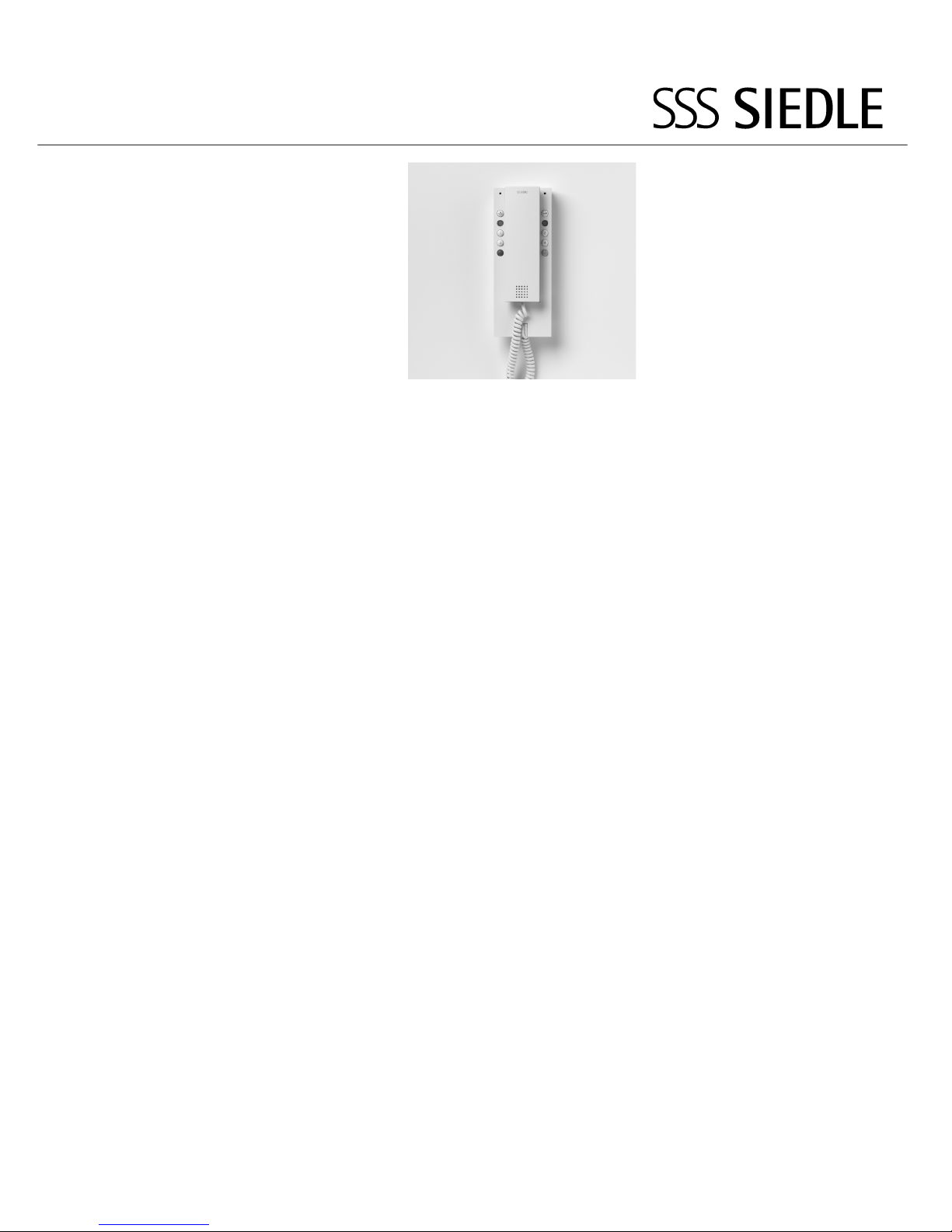
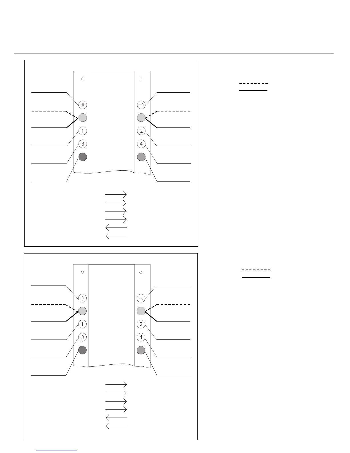
Defining the configuration
Basic configuration 1
Basic configuration 2
Basic configuration 1
As-delivered status
LED flashing
LED static
3 inputs
E2 - E3 10-30 V DC floating
S1/S2 are transistor outputs
0-30 V DC max. 10 mA
1 speech channel
Call tones
Call connected = continuous
Engaged = single short
Call = single long
Door call 1 = threetone slow
Door call 2 = threetone fast
Storey call 1 = two-tone
Fire alarm = alphatone 2
Basic configuration 2
LED flashing
LED static
3 inputs
E2 - E3 10-30 V DC floating
S1/S2 are transistor outputs
0-30 V DC max. 10 mA
2 speech channels
Call tones
Call connected = continuous
Engaged = single short
Call = single long
Door call 1 = threetone slow
Door call 2 = threetone fast
Storey call 1 = two-tone
Fire alarm = alphatone 2
Door release
No function
Input E3
Calls addr. 1
Calls addr. 1
Calls addr. 1
Light (F0)
Call display
No function
Door release 2
Not assigned
Output 2
Storey call 1
Alarm call
LED right
Reference point
Sec. signal unit
Button 5
E1 Input
E2 Input
E3 Input
G for E2, E3
S1 Output
S2 Output
Door release
No function
Call silencing
Call silencing
Calls addr. 2
Calls addr. 1
(switchboard)
Light (F0)
Call display
No function
Door release 2
Internal call
Calls addr. 3
Storey call1
Alarm call
Personnel present
Reference point
Sec. signal unit
Button 5
E1 Input
E2 Input
E3 Input
G for E2, E3
S1 Output
S2 Output
Page 5

11
Basic configuration 3
LED flashing
LED static
3 inputs
E2 - E3 10-30 V DC floating
S1/S2 are transistor outputs
0-30 V DC max. 10 mA
2 speech channels
Call tones
Call connected = continuous
Engaged = single short
Call = single long
Door call 1 = threetone slow
Door call 2 = threetone fast
Storey call 1 = two-tone
Fire alarm = alphatone 2
Basic configuration 4
LED flashing
LED static
3 inputs
E2 - E3 10-30 V DC floating
S1/S2 are transistor outputs
0-30 V DC max. 10 mA
2 speech channels
Call tones
Call connected = continuous
Engaged = single short
Call = single long
Door call 1 = threetone slow
Door call 2 = threetone fast
Storey call 1 = two-tone
Fire alarm = alphatone 2
Defining the configuration
Basic configuration 3
Basic configuration 4
Door release
No function
Reassurance
lamp
Cancel emergency call
Calls addr. 2
Calls addr. 1
(switchboard)
Light (F0)
Call display
No function
Door release 2
Not assigned
Actuate emergency call
Storey call 1
Emergency call
Presence
Reference
Sec. signal unit
Reassurance lamp
E1 Input
E2 Input
E3 Input
G for E2, E3
S1 Output
S2 Output
Door release
Call display
Call silencing
Call silencing
Internal call
Calls addr. 1
(switchboard)
Light (F0)
No function
Doormatic
Doormatic ON
Camera ON
(Addr. no.99)
Output 2
Storey call1
Alarm call
Attention tone
Reference point
Sec. signal unit
Button 5
E1 Input
E2 Input
E3 Input
G for E2, E3
S1 Output
S2 Output
Page 6

12
Basic configuration 5
LED flashing
LED static
3 inputs
E2 - E3 10-30 V DC floating
S1/S2 are transistor outputs
0-30 V DC max. 10 mA
2 speech channels
Call tones
Call connected = continuous
Engaged = single short
Call = single long
Door call 1 = threetone slow
Door call 2 = threetone fast
Storey call 1 = two-tone
Fire alarm = alphatone 2
Basic configuration 6
LED flashing
LED static
3 inputs
E2 - E3 10-30 V DC floating
S1/S2 are transistor outputs
0-30 V DC max. 10 mA
2 speech channels
Call tones
Call connected = continuous
Engaged = single short
Call = single long
Door call 1 = threetone slow
Door call 2 = threetone fast
Storey call 1 = two-tone
Gas alarm = alphatone 2
Vip call = special tone
Defining the configuration
Basic configuration 5
Basic configuration 6
Door release
Call display
Call silencing
Call silencing
Door actuation
Calls addr. 1
(switchboard)
Light (F0)
Single
concierge
Input E3
Concierge ON
Camera ON
(Addr. no. 99)
Output 2
Storey call 1
Alarm call
LED left
Reference point
Sec. signal unit
Button 5
E1 Input
E2 Input
E3 Input
G for E2, E3
S1 Output
S2 Output
Door release
Call display
Call silencing
Call silencing
Cancel alarm
Calls addr. 1
(switchboard)
Light (F0)
Callback
request
No function
Set callback
Calls addr. 2
Output 2
Storey call1
Alarm call
Gas alarm
Reference point
Reassurance lamp
Button 5
E1 Input
E2 Input
E3 Input
G for E2, E3
S1 Output
S2 Output
Page 7

4
3
6
7
11
10
12
15
1
1
2
5
9
8
13
14
1
3
2
Page 8

5
6
7
8
Page 9

10a
9
Page 10

10b
10c
Page 11

2
11
Adresseinstellung
Address setting
Prog.-Mode
manuell/
extern über
SCO 740-0
manual/
extrenal via
SCO 740-0
Page 12

16
© 2002/08.02
Printed in Germany
Best. Nr. 0-1101/031902 D, GB
S. Siedle & Söhne
Telefon- und Telegrafenwerke
Stiftung & Co
Postfach 1155
D-78113 Furtwangen
Bregstraße 1
D-78120 Furtwangen
Telefon +49 (0) 7723/ 63-0
Telefax +49 (0) 7723/ 63-300
www.siedle.de
info@siedle.de
Belegung der Bedienoberfläche
Assignment of the user interface
LED blinkt
LED leuchtet statisch
LED flashes
LED lights continuously
 Loading...