

Page 1
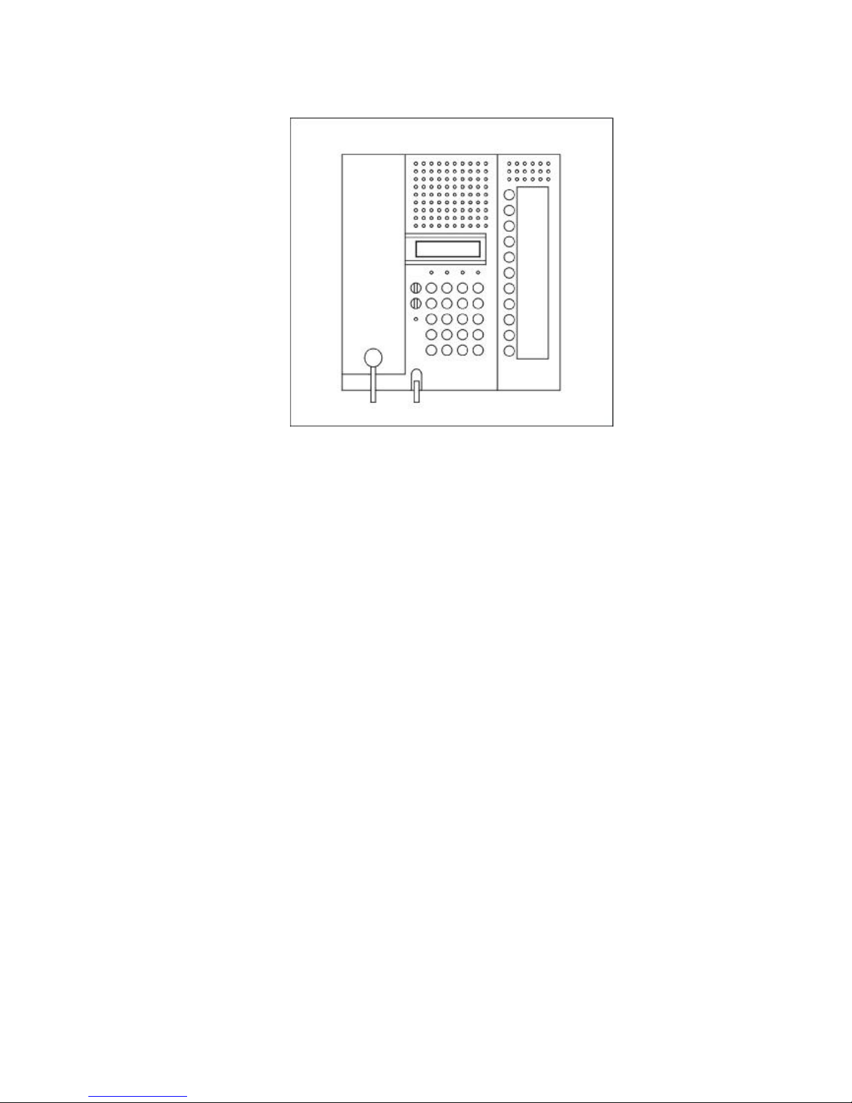
Electronic special departement
Siedle Multi
Programming
instruction
HT 644-02
05.03
ex Vers. ES 04.5x
Page 2
2
HT 644-02
General information
This Programming Instruction is valid for units from software version ES 4.5x .
Older units from software version 4.16 onwards can be upgraded through replacing the
EPROM at any time. Additionally, the D7 SMD-diode must be removed from the main printedcircuit-board.
Programming is performed step by step using both a display screen and the related control
keys which control the dialog. Each entry must be confirmed.
Before starting programming, both all system subscribers must be connected and the system
must be activated.
Desktop for programming
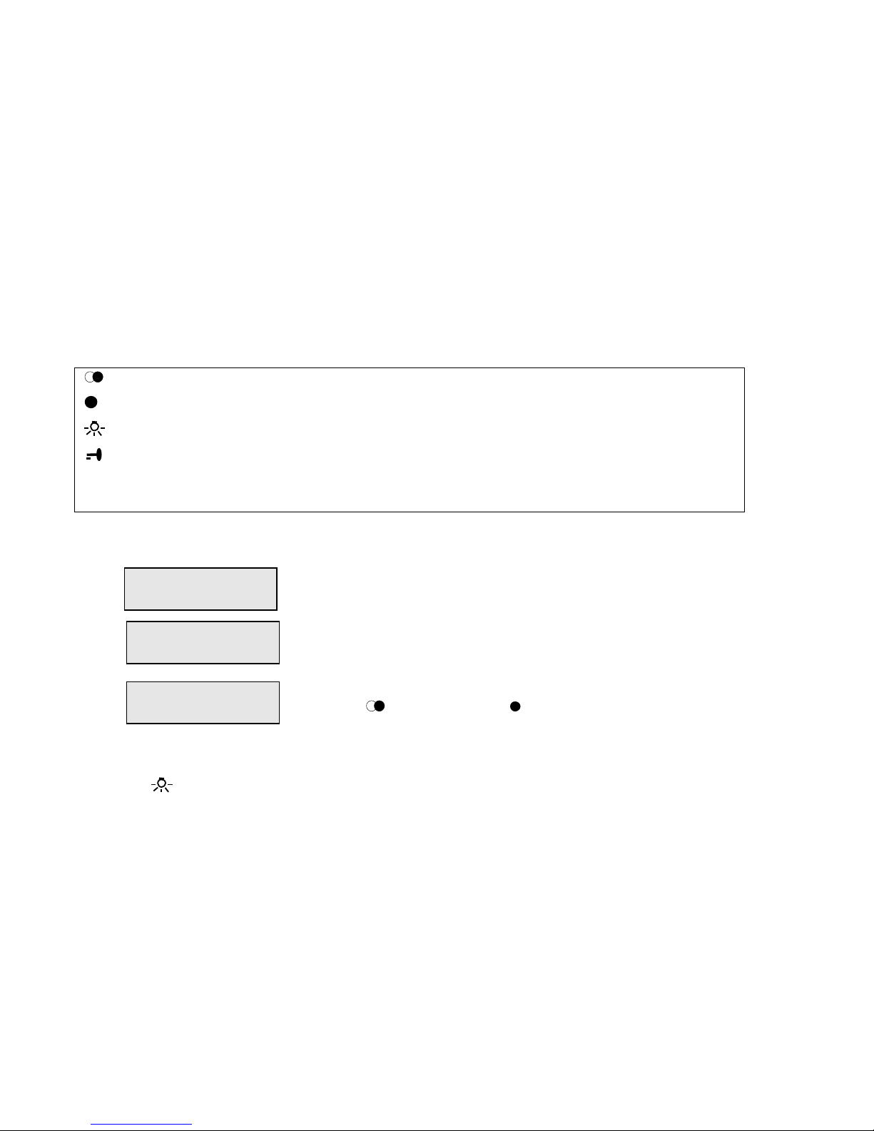
In addition to the display screen, the following keys are required:
Invoking the programming menu
Take off the handset
Enter 0000
Enter password
8888
The particular menu items can be selected through
the
(forward) resp. (backward) keys.
Exiting the programming menu
Press the key, or hang up the handset
Initializing
Employing one HT 644... internal telephone, an initialization must be executed before the
system is commissioned-up for initial operation. (please, refer to menu item 12.01). Through
this initialization, all units which are connected to the system are entered and a status
catalogue of the particular units is created. The status catalogue is needed to communicate
status information to all units, such as assignment of the corresponding subscribers to a
subscriber group or functionality, etc.. Not until after executing an initialization, correct
switching functions, using of group speech paths, and call redirections are possible.
After each upgrading of the system, or each modifying of functions, an initialization is required.
Info function
Unit type, software version, unit address, and the assigned subscriber number are shown in
the display screen through selecting the i key.
Forward Invokes either the next menu or the next submenu item.
Backward Invokes either the next menu or the next submenu item.
Exit Completes either the programming menu or a submenu.
Confirm Applies the entered values in the memory.
0 -9Data Input data, programming values, and decisions made (yes / no)
0000
Please dial
####
Code word
Programming menu
< Back Forward >
Page 3
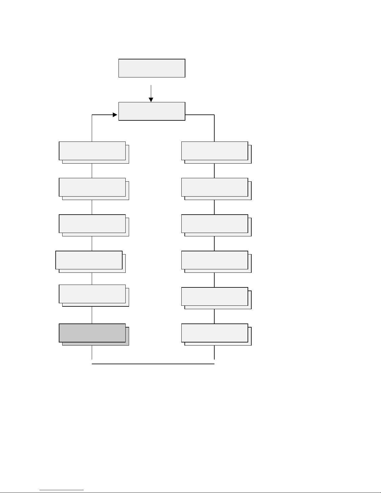
Outline of menus
To commence programming
throught the
programming menu:
Lift handset
Enter "0000"
Enter the password (8888)
121
112
103
94
85
7*6
7* only in combination with MFM 611-10
Programming menu
< back Forward >
Set clock
with <OK>
Change call no
assign. with <OK>
Please dial
Alarm & emerg.
menu with <OK>
Output 12 activate with <OK>
Switch LED 4
with <OK>
Areas / ft.
Enable/dis <OK>
Basic parameters
programming <OK>
TLP call menu
with <OK>
Coll. call menu
with <OK>
Call back menu
with <OK>
MFM program
with <OK>
Service menu
with <OK>
Page 4

3
Programminginstruction
Schedule of ContentsPage
1 Basic parameters
Setting-up the language (G, UK, F, NL, I)
Unit address, group no., speech circuit enable, active/passive,
video mode, compatibility,
4
2 Door-parallel-call menu
Receiving a global or local door-parallel call
8
3 Collective-call menu
Authorization to receive, authorization to send, group-collective call
9
4 Alarm-and-emergency-call menu
Processing both alarm and emergency calls, fire alarms
10
5 Callback menu
Storing and showing internal background door calls
12
6 Assigning subscriber numbers
Assigning subscriber numbers freely to subscriber addresses
13
7∗ Allocating MFM ∗
Allocating MFM keys both to functions and subscriber numbers
15
8 Activating output 12
Activating the output in combination with various functions
18
9 Switching LED 4
Allocating the LED to various functions
20
10 Areas / functions of Enable / Disable
Enabling / disabling the desktop (key functions)
22
11 Setting the system clock
Showing the current clock, internal / external
24
12 Service menu
Initialisation, default settings, show data transfer,
Selecting the video operating mode
25
General informations
Documentation items
27
∗) is not possible other than in combination with a MFM 611-10 unit
Page 5
4
HT 644-02
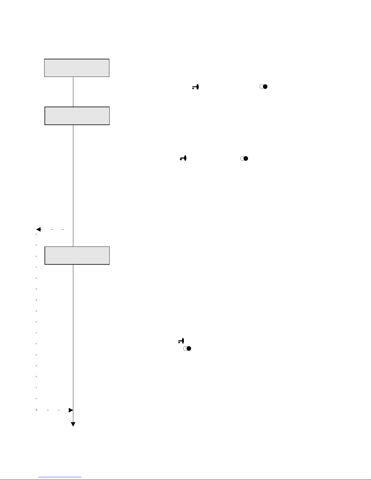
1 Basic parameters menu
Setting of general functions and options
⇒ open menue with , or Continue with
.
1.01 Unit address
Each unit requires its own logic unit address.
Up to a maximum of 4 units can be operated in parallel under
the same address.
⇒ Enter unit address (1 – 254 / 500) and
⇒ confirm with , continue with
.
Please note:
The 0, 255, and 256 addresses must not be employed.
When operating in the active/passive mode, an own address
(under which the unit can be reached in both the passive and
active mode) must be allocated to each unit which is used as
switching exchange.
In this case, address 1 must not be employed.
1.02 Assignment to a subscriber group
∗ (the menu is not shown other than in stage 2)
Siedle Multi systems of stage 2 can be configured as either a
total system with 2 global speech paths or a group system
with both one global and a maximum of 15 local speech
paths.
One group address is assigned to each subscriber to a
group, in addition to the logic address.
Two global speech paths: Group address = 0
Group system: Group address is = 1 - 15
⇒ Enter respective group address and
confirm with
Continue with
.
Tip:
∗)
The programmed value of a group assignment must
correspond to the wiring of the group speech paths
7xx / 8xx. When executing the planning, this requirement
must already be regarded.
The group address must be setup to "0" in backward
compatible systems.
Speech circuit 2
Basic parameters
programming <OK>
Log. address
1-500 _ _ 1
Group ?
0-15 0
Page 6
5
Programming-
instruction
1.03 Speech circuit 2
The HT 644-.. unit is prepared for connecting two physical
speech paths.
If the second speech path is not wired, or if it is employed
as a group speech path, it must be deactivated here.
⇒ Deactivate speech path two: Enter "0"
⇒ confirm with , Continue with
..
Please note:
The (global) speech path 2 must be deactivated in group
systems in order to avoid malfunctions.
1.04 Active / passive mode
(is only possible in combination with a MFM 611-10 unit)
In systems which consist of several switching exchanges,
every unit can take both the active and passive state, that is,
the "switching-exchange function" (address 1) can be
switched-over to each switching exchange. Only one
switching exchange can be switched into the active state, at
any time. In addition to the original address, an additional
(virtual) address 1 which is allocated to this switching
exchange which assumes all functionalities of the internaltelephone-switching exchange. Activation is through a MFM
key (please, refer to item No. 7.05, „Allocating MFM“). Exactly
that unit becomes active at which the respective MFM key is
actuated, however, all other switching exchanges become
automatically passive. The status message „A“ or „P“ shows
the respective operating state in the display screen.
⇒ Activate the active / passive mode:
Enter "1" and confirm with , Continue with
..
Please note:
The active/passive mode must be set at all switchable
switching exchanges.
No unit must be programmed as original address 1 .
Call redirections cannot be performed from units with enabled
active/passive mode.
Video mode
An HT 644.. unit with active/passive function is also possible
in combination with an HTZ 442-0 unit, however, in the
"backward compatible" operational mode only. When the
active/passive mode is activated, all special functions for the
"switching exchange" (lighting, F functions, switching
functions, etc,) must be allocated to MFM keys, however, the
functions for the original address (passive state) are allocated
to the special keys of the original-HT keyboard.
Speech circuit 2
inst. Y=1/N=0 1
aktive/passive
mode? Y=1/N=0 0
Page 7
6
HT 644-02
1.05 Video mode
In combination with the VCO 640 video controller, a monitor
which is allocated to the HT 644-.. unit can be directly
connected by means of the integrated video-control
interface, or by means of a porter’s-desk camera through
output 12.
The respective video mode must be set at the HT.
Video mode 0 = no VCO-640 unit is part of the system
1 = convenient one-channel video
2 = is not used
3 = multichannel video (VCS system)
⇒ Enter number of the system-video mode,
confirm with
or continue with
1.06 System mode of operation
Two different operating modes can be selected for the
Siedle Multi system:
Backward compatible (old):
For older systems (with HT 44x-0 or HT 64x-0 units) with an
address range of a maximum of 254 subscribers, and with
HTZ 442-0 units, as well as equipped with a limited range of
functions (in general for systems with a delivery date before
2001).
Stage 2 (new):
For systems with an expanded range of functions and
addresses up to a maximum of 500 subscribers (in general
for systems with a delivery date from 2002, and/or the ES
235 option).
⇒ If “backward compatible“ is required: Enter "1"
If stage 2 is required: Enter "0"
⇒ confirm with .
Continue with
.
Please note:
As a mixed mode is not possible, all units of the total
system must be programmed to the very same operating
mode.
Language
Video mode ?
0-3 0
Compatible ?
Y=1/N=0 0
Page 8
7
Programming-
instruction
1.07 Setting-up the language of the respective country
The text output in the display screen can be setup in 5
country languages at any time.
G = 1German
UK = 2English
F = 3French
NL = 4Dutch
I = 5Italian
⇒ Enter the respective digit and confirm with
Continue with
.
TLP call menue
⇒ Exit to main menu with
Land/Country ? 1
D=1 GB=2 F=3 NL=4
Page 9
8
HT 644-02
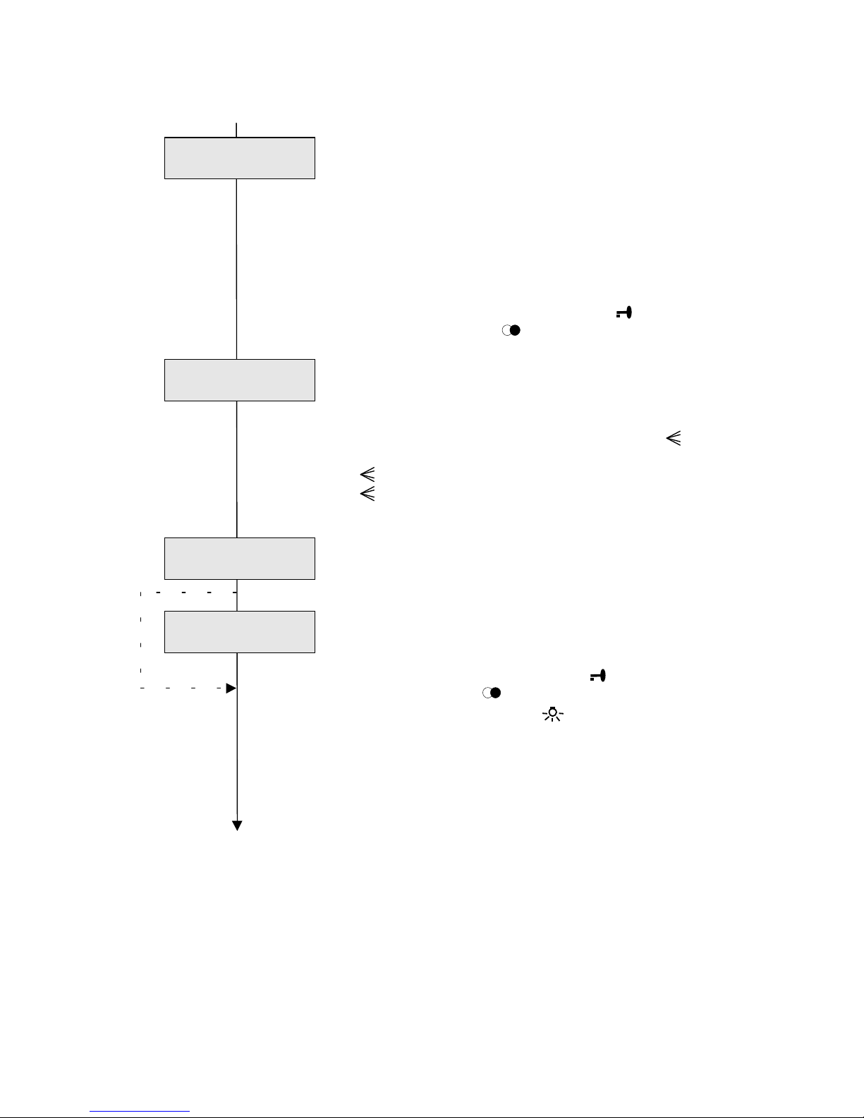
2 Door-parallel-call menu
The door-parallel call is a special, simultaneous door call to
subscribers with different unit addresses. A global doorparallel call to any number of subscribers is possible in
Siedle Multi systems.
In addition, a further parallel call per group can be
programmed in group systems (stage 2).
⇒ Open menu with "1", confirm with
or continue with
2.01 Receipt of a door parallel call (in general)
Enable ready-to-receive state for a global door parallel call.
2.02 Receipt of a door parallel call for groups
Enable ready-to-receipt state for a door parallel call within
the own group.
⇒ Enable with "1", confirm with
or continue with
⇒ Exit to main menu with .
Please note:
The corresponding door-parallel call (calling function) is
programmed in the door-loudspeaker controller.
Up to a maximum of 4 subscribers can be programmed
without any limitations to a global or a group-parallel call
receipt.
When the power supply is calculated for systems with more
than 4 subscribers, the double connected load must be
applied for each subscriber.
In combination with multichannel-video applications, the
receipt of door-parallel calls must be enabled into the Video
controller VCO 640-.. for the corresponding monitorswitching outputs.
Collective-call menu
Receive TLP call
group Y=1/N=0 0
Receive TLP call
gener.. Y=1/N=0 0
TLP call menu
with <OK>
Page 10
9
Programming-
instruction
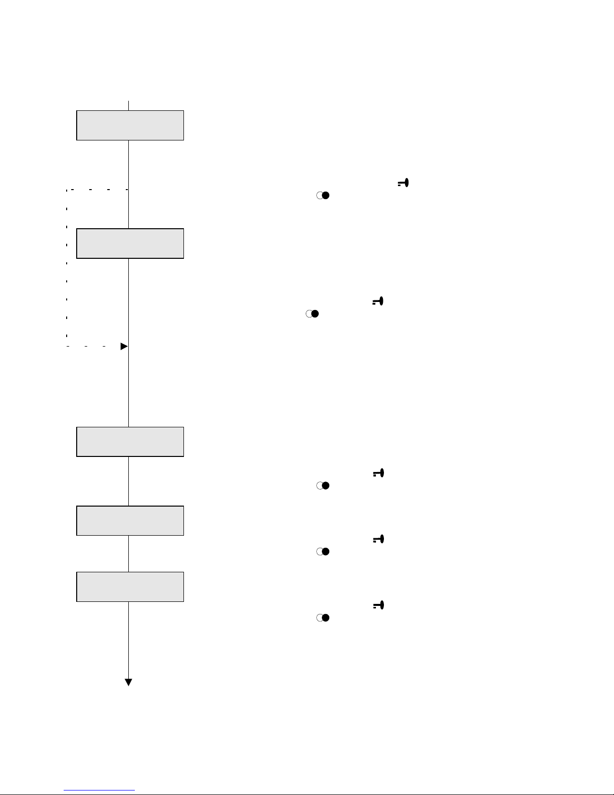
3 Collective-call menu
In the Siedle Multi system, collective calls can be enabled
and received by means of the HT 644-... unit.
Two types of collective calls are possible:
- A generic-collective call to all subscribers with
authorization to receive.
- A group-collective call to subscribers within the selected
group only .
⇒ Open menu with "1", confirm with
or continue with
3.01 Authorization to send collective calls
Authorization to send / transmit collective calls
Tip:
Collective calls are enabled by pressing the key
and entering the respective group number.
0 = generic-collective call
1-15: Group-collective call
3.02 Authorization to receive a collective call
– in general
Authorization to receive generic-collective calls
3.03 Authorization to receive group-collective calls
Authorization to receive collective calls from the own group
⇒ Activate with "1", confirm with .
Continue with
.
Exit to main menu with .
Please note:
A maximum of 40 collective-call-receiving subscribers are
possible in the system.
Alarm and emergency
call menu
Receive call
group Y=1/N=0 0
Coll. call.
Y=1/N=0 0
Receive call
gener. Y=1/N=0 0
Coll. call menu
with <OK>
Page 11
10
HT 644-02
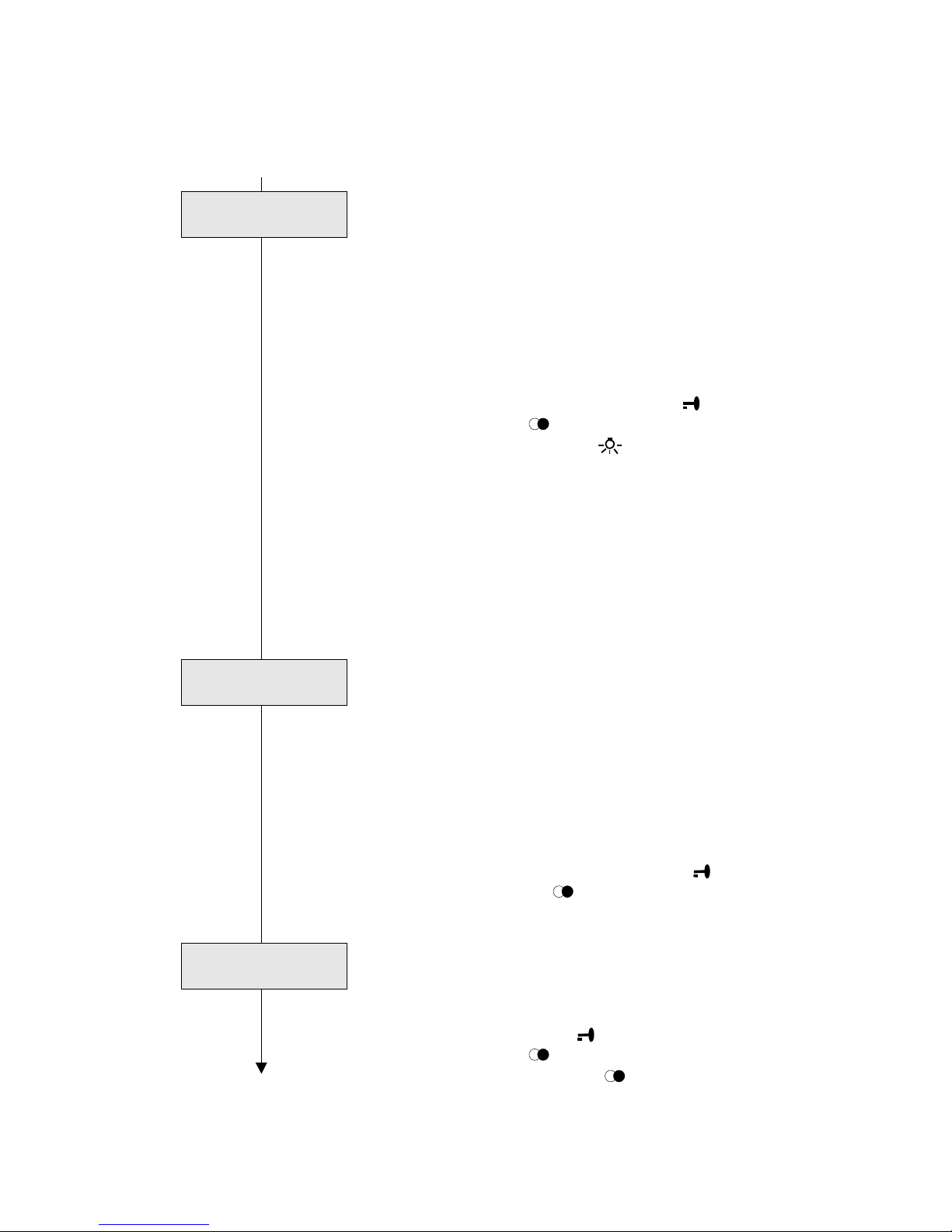
4 Alarm-and-emergency-call menu
Up to 15 alarm and emergency calls can be received,
stored, and processed through the HT 644-02.. unit.
They are shown both in the screen display and the LED 1.
⇒ Open menu with "1", confirm with
or continue with
4.01 Receiving fire-alarms
An acoustic-fire-alarm signal can be activated by means of
the SCO 740-0 system controller.
The authorization to receipt can be programmed.
⇒ Enable with "1", confirm with .
Continue with
.
∗)
∗) Please note:
In the mode ""backward compatible", it is impossible to
receive both an announcement and a fire-alarm signal
simultaneously. If the collective-call-receipt function is
activated, the fire-alarm menu is not displayed.
4.02 Enabling emergency-call processing and
displaying
⇒ Enable with "1", confirm with .
or continue with
4.03 Enabling alarm 1-call processing and displaying
⇒ Enable with "1", confirm with .
or continue with
4.04 Enabling alarm 2-call processing and displaying
(Gasalarm)
⇒ Enable with "1", confirm with .
or continue with
Cancel alarm
Process alarm 1.
calls. Y=1/N=0 0
↓ Alarm / em. call
↓
menu with <OK>
Rec. fire alarm
Y=1/N=0 0
Process emerg.
calls. Y=1/N=0 0
Process alarm 2.
calls. Y=1/N=0 0
Page 12
11
Programming-
instuction
4.05 Authorization to edit alarm calls
Emergency calls can be cleared at the enabling place only.
Alarm calls type 1 are cleared through both a call of the
enabling subscriber and establishing a speech path.
In this menu item, a decision is made whether each HT 644
unit (e.g. a passive switching exchange) or the active
switching exchange (address 1) has the exclusive
authorization to perform the clearing process, when a call is
received.
⇒ Select with "1" or "0", confirm with
or continue with
⇒ Exit to main menu with .
Please note:
Storing and displaying of both alarm and emergency calls is
in each unit which is enabled for receiving both alarm and
emergency calls.
However, the acoustic signaling and, if there is an
authorization, the possibility of clearing are only possible
through the unit with the address 1 (switchboard function).
4.06 Signalization period
When an alarm or emergency-call is received, a special
signal is sounding at the HT 644 unit.
The signalization period can be setup from 1 to 98 seconds.
When a setup of 99 seconds is made, the signal sounds
without any time limit.
The signal can be deactivated through pressing the "0" key
at any time. If there are installed further signaling units in
the system, their signaling is also deactivated.
⇒ Setup with keys 1 - 9, confirm with .
or continue with
4.07 Clear memory (alarm / emergency calls)
All stored emergency calls and alarm calls will be deleted
(only in this unit)
⇒ Clear memory with
or continue with
⇒ Exit to main menu with
.
Callback menu
Signal time sec.
Cont. = 99 5
Cancel alarm
Adr1=1 all=0 1
Clear memory
with <OK>
Page 13
12
HT 644-02
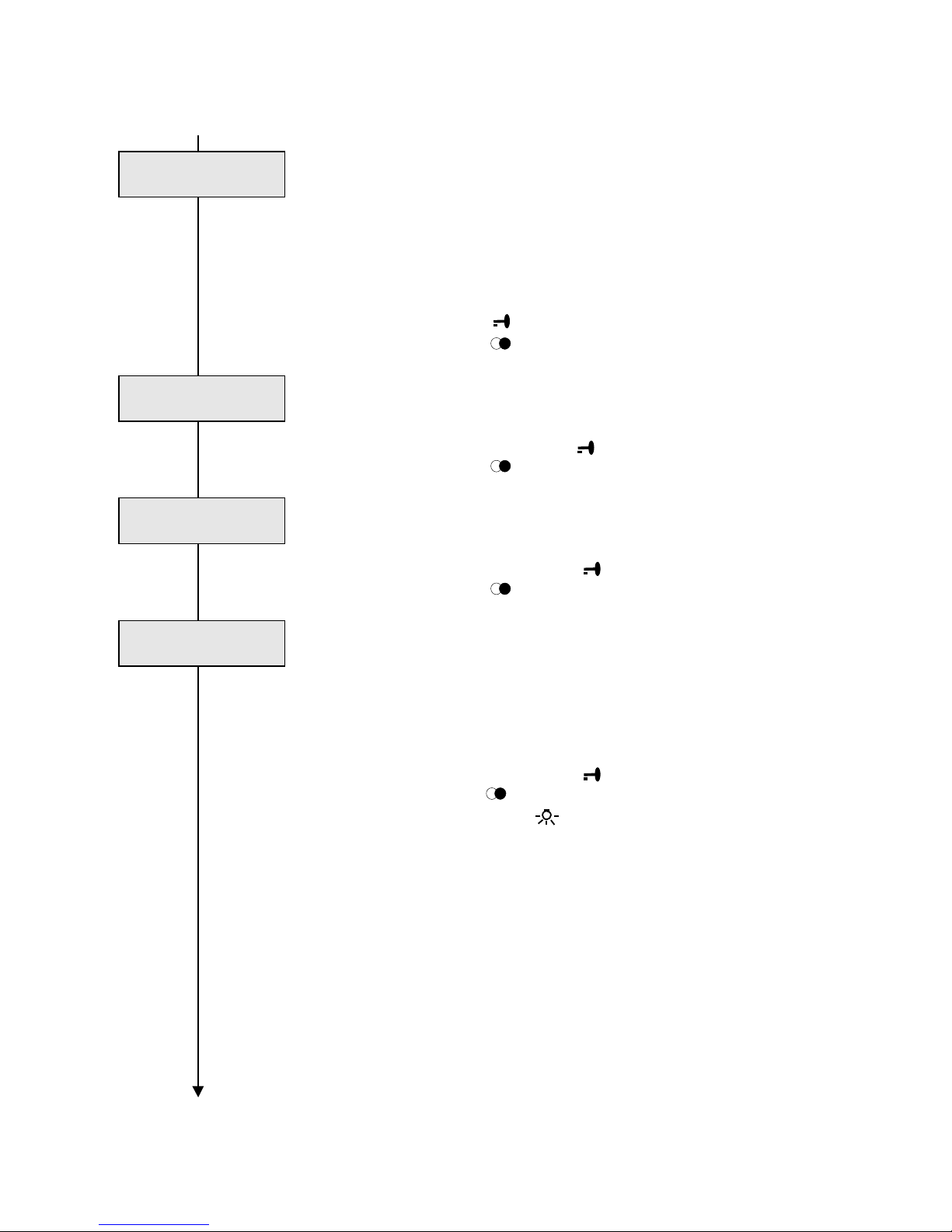
5 Call back menu
Up to a maximum of 15 at all of non-answered calls can be
both stored and displayed as a callback request in the
HT644 unit:
- non-accepted calls (internal calls)
- background calls (during a call)
- non-accepted door calls
⇒ Open menu with
or continue with
5.01 Enable call storing
Storing non-accepted internal calls
⇒ Enable with "1", confirm with
or continue with
.
5.02 Enable of background-call storing
Storing calls during a speech connection (internal calls)
⇒ Enable with "1", confirm with
or continue with
5.03 Enable door-call storing
While a speech connection is existing, or during the 1minute standby period, non-accepted door calls are stored
for additional two minutes.
Displaying is provided with the "∗" additional identification
sign.
⇒ Enable with "1", confirm with
or continue with
Exit to main menu with .
Tip:
Stored callback requests are cleared through a subscriber
call or through activating the respective door loudspeaker.
When the handset is hung up and the subscriber number or
address of a stored subscriber is entered, the stored
subscriber number is also cleared.
If there are callback requests, LED 3 is illuminated in
parallel to the display screen.
If there are more than 15 callback requests or alarm
/emergency calls into store, they get lost.
Alarm / emergency calls have priority in storing.
Enabling should be performed restrictively, in order to avoid
any overloading of the display screen.
Call no. assignment menu
Store calls
Y=1/N=0 0
Call back menu
with <OK<
Store background
calls. Y=1/N=0 0
Store door calls
Y=1/N=0 0
Page 14
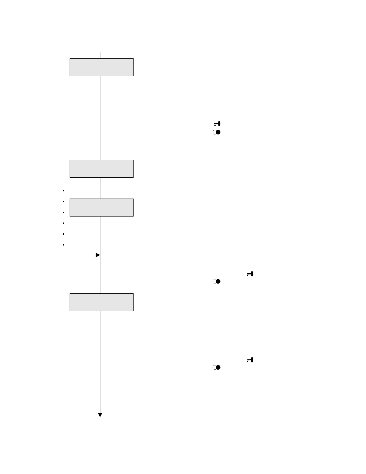
13
Programming-
instruction
6 Assigning subscriber numbers
Any subscriber number consisting of a maximum of four
digits can be assigned to a unit address (1 - 500). This
subscriber number is used for both calling the subscriber
and showing in the display screen. Thereby, any type of
hierarchical number-systems which are clearly for the
subscribers can be created.
⇒ Open menu with
or continue with
Assigning subscriber-numbers automatically
6.01 Setup the table 1:1 (in binary coding)
The subscriber-number table is setup identical to the
address table, i.e. address 1 equals subscriber number 1.
This equals the delivering state of the HT 644 unit.
∗)
6.02 Setup table 1:1 (in BCD coding) ∗
The subscriber-number table is setup identical with the
address table in BCD coding. This setting is required for
older systems which are programmed in the BCD code (e.g.
for replacing a HT 311/351MC unit). In this case, freely
assigning of subscriber-numbers is not possible.
∗) This menu item is shown in the "backward compatible"
operating mode only.
⇒ Enable with "1", confirm with
or continue with
.
6.03 Deleting a table
The subscriber-number-assignment table can be deleted
completely. Thereby, all subscriber numbers which are
assigned to the corresponding unit addresses (input
numbers) are both deleted (i.e. eliminated) in the desktop
and any call entry through the keyboard is no longer
possible.
⇒ Enable with "1", confirm with
or continue with
continue with
Editing table through system
Tip:
Before starting any individual subscriber-number
assignment, deleting is always recommended.
In this way, double assignments of addresses and/or
subscriber numbers which cause conflicts can be
prevented. Furthermore, subscribers which should not be
called can be deleted from the desktop, simply through
"non-assignment ".
Delete table ?
Y=1/N=0 0
Set table BCD 1:1
Y=1/N=0 0
Change call no.
with <OK>
Set table 1:1
Y=1/N=0 0
Page 15
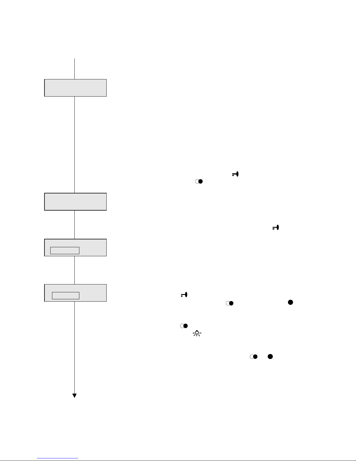
14
HT 644-02
6 Assigning subscriber numbers, continued
6.04 Editing the table through the system
The subscriber-number table can be transmitted
through the system bus to all subscribers, in order to
avoid manually entering with each subscriber. The
"Initialization" function at the HT 644 unit performs this
transmission (please, refer to menu 12.01).
This menu item accomplishes to enable or disable
receiving, and thereby overwriting the current table at
the particular HT 644 unit. Enabling makes only sense,
if the same subscriber-number assignment is desired by
all subscribers.
⇒ Release with "1", confirm with
or continue with
6.05 Editing the table
The process of assigning the subscriber-number list can
be started from any address.
⇒ If required, enter start address, confirm with .
Upper display-screen column: Address
Lower display-screen column: Assigned subscriber
number, however, each address can be assigned to
one subscriber number only, consisting of a maximum
of 8 digits.
⇒ Enter subscriber number (8-digit), e.g. “09999999”,
confirm with
go to the next address with
, (backwards with )
Enter next subscriber number (to be assigned to
address 2).
or skip with
⇒ Exit to start with .
Allocating MFM
menu
Tip:
For checking purposes, use either the
or key in
order to scroll through the table.
Please, make sure that identical subscriber numbers
are not assigned to several addresses. Our
recommendation is: Delete table before assigning
individual subscriber numbers. If the "0" subscriber
number is entered to one address, this address can not
be called through the data-entry keyboard any longer.
Thereby, the subscribers which are callable from this
unit can be selected.
..........1
A
...............1 N
Change table via
system Y=1/N=0 0
Change table
from address 001
...........1 A
09999999 N
Page 16
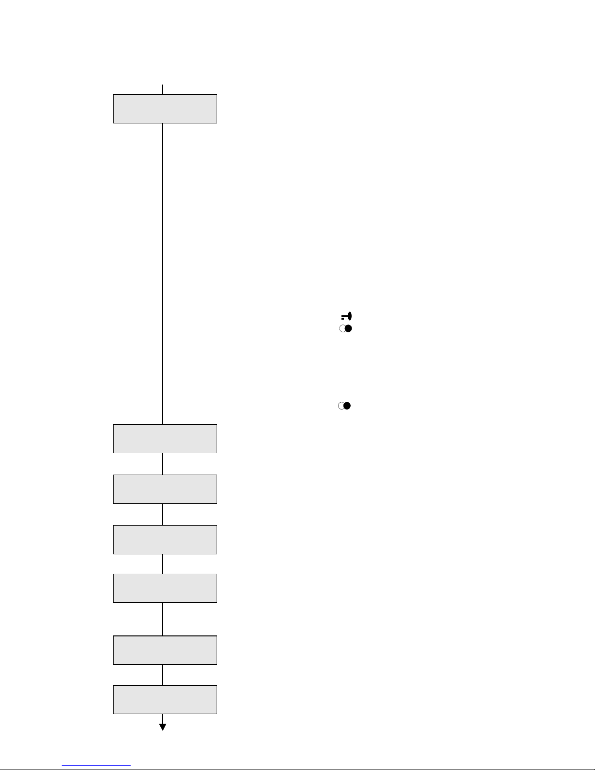
15
Programming-
instruction
7 Allocating of MFM keys
Up to a maximum of 3 MFM-611-10 units, with 10
programmable keys each, can be connected to a HT 644-..
unit. Subscriber calls as well as both control and switching
functions can be freely allocated to the keys, in order to
facilitate operating of the unit, especially regarding systems
with complex functions, e.g. as a switching exchange. Each
key can be double-allocated:
- Single press of the key = 1st function
- Double press of the key (double click) = 2nd function
Tip:
It is recommendable, to program keys single only for both
calling and elementary controlling functions, but single with
double press for safety functions (active/passive, alarm) and,
however, to use both functions of the key for
activate/deactivate functions (e.g. for a camera).
⇒ Open menu with
or continue with
Allocating:
⇒ Enter desired function, after entering press the desired key
which has to be programmed, an acknowledge signal
sounds, next entering
⇒ or continue with
7.01 Allocating teleswitching functions
Functions from 1 to 9 can be entered.
The functions from 10 to 15 should not be entered.
7.02 Allocating subscriber numbers
With entered subscriber numbers, the subscriber number
which consists of a maximum of 4 digits must be entered,
however, with a 1:1 allocation, the address must be entered.
7.03 Allocating switching functions (on, or activate)
Enter address to on or activate switching function
7.04 Allocating switching functions (off, or deactivate)
Enter address to off or deactivate switching function. If
applicable, allocate to on or activate function key, however,
with double click.
7.05 Allocating with "active / passive" switch-function
Our recommendation is: Allocate the function to a key with
double click:
7.06 Allocating with "Clearing speech-path" function
Enables the global speech path 1 (priority function)
MFM ass. to
ON fct. _ _ _
Allocate MFM
with <OK>
MFM ass. to
Remote fct. _ _
MFM ass. to
Call number. _ _ _ _
MFM ass. to
OFF fct. _ _ _
MFM ass. to
Aktive / passive
MFM ass. to
Clear SPW
Page 17
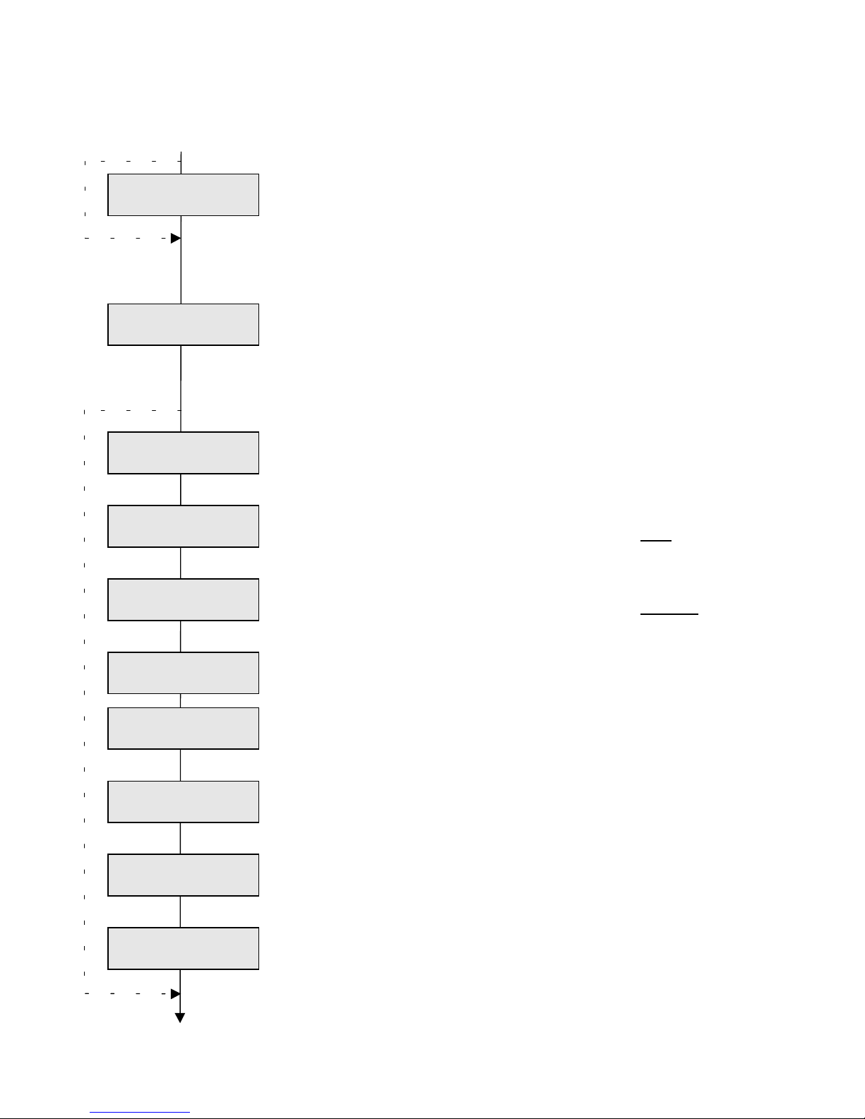
16
HT 644-02
7 Allocating MFM continued
∗)
7.07 Allocating the "triggering fire alarm" function
Our recommendation is: Allocate the function to a key
through a double click:
∗) Function is not available if the collective-call menu is
deactivated.
7.08 Allocating the "switching output 12" function
When connecting either an AR 85052.. or an AR 85911..
connecting relay, a potential-free contact is available:
The following functions are only available in Stage-2
systems:
7.09 Allocating a “call follow me” function
Configurate the control key if invoking of a general callfollow-function is desired ( individual call no.)
7.10 Allocating a "selective call-follow me" function
Enter both number or address of the subscriber from whom
the call must be forwarded (GET function):
7.11 Allocating a "selective call-forwarding" function
Enter both number or address of the subscriber to which the
call must be forwarded .
7.12 Allocating a "concierge group forwarding" fct.
Enter number of "concierge group" to activate by the button
7.13 Allocating a "Single concierge forwarding" fct.
Configurate the control key to activate /deactivate the funct.
Enter the address/number of the receiver for this function.
7.14 Allocating the "switching doormatic" function
Control button for activating / reset the doormatic function
7.15 Allocating the "camera continuously on" function
Control key for continuously activating a camera.
Enter the camera address
7.16 Allocating the " camera time controlled on" fct.
Control key for temporarily activating a camera.
Enter the camera address
Please note:
The functions 7.15 / 7.16 are only possible in combination
with the VCO 640-.. video-control system.
more MFM allocations
MFM ass. to
** Fire alarm **
MFM ass. to
Follow me
MFM ass. to
Reroute . _ _ _ _
MFM ass. to
Output 12 3 sec
MFM ass. to
C. temp. _ _ _ _
MFM ass. to
Doormatic
MFM ass. to
S. Conc. _ _ _ _
MFM ass. to
Follow . _ _ _ _
MFM ass. to
Caretaker (1-4) _
MFM ass. to
C. cont. _ _ _ _
Page 18
17
Programming-
instruction
14 Allocating MFM continued
7.17 Allocating the door release 2 function
Control key for activating the door release 2 in combination
with a ETC 640-01.
7.18 Showing the current key allocation
Actuate the corresponding MFM key (through single or
double click). The corresponding allocation is shown in the
display screen.
7.19 Deleting the key allocation
Actuate the corresponding MFM key (through single or
double click). The corresponding allocation is deleted.
⇒ Exit to start with
Output 12 menu
Clear allocation
MFM button
MFM ass. to
Door release 2
Display ass. of
MFM button
Page 19
18
HT 644-02
8 Activating output 12
The HT 644-.. unit is furnished with a transistor OCswitching-output which can be selected through both
various actions or system states, e.g. the NS 541-0 unit can
be directly connected as a secondary-signaling unit.
If switching outputs are required, the AR 85052..., AR
85911..., etc., connecting relays are recommendable.
⇒ Open menu with
or continue with
Selecting:
⇒ Enable the desired function through „1,
confirm with
or continue with
Please note:
Some functions can be parallelly switched to output 12,
however, other functions only alternatively. The parallellyintrudeable functions are identified with a ∗1(2..)) suffix.
8.01 Activating an output when an emergency call is
existing
∗1) When a new emergency call is existing, the output is
activated until the calling tone (CNG) is deactivated.
8.02 Activating an output when an alarm call is existing
∗1) When a new alarm call is existing, the output is
activated until the calling tone (CNG) is deactivated.
8.03 Activating an output when an callback request is
existing
∗1) Whenever a callback request (please, refer to menu 5)
is existing, the output is activating.
8.04 Activating the output when a call is existing
∗2) Whenever a new call is existing in parallel to a calling
signal, the output is activating.
8.05 Activating an output when a door call is existing
∗2) Whenever a door call is received during an existing call,
the output is activating.
8.06 Activating an output when a floor call is existing
∗2) Whenever a floor call is received during an existing call,
the output is activating.
more output 12
Tip:
When a call, door call, or floor call is received, a NS 541-0
secondary-signal unit can be directly connected.
with call back
Y=1/N=0 0
↓ Output 12 acti
↓
vate with <OK>
with em. call
Y=1/N=0 0
with alarm call
Y=1/N=0 0
with normal call
J=1/N=0 0
with door call
J=1/N=0 0
with storey call
Y=1/N=0 0
Page 20
19
Programming-
Instruction
8 Activating output 12 continued
8.07 Activating the output through a switching function
Activating through a switching function to the HT 644-.. unit
address for 3 sec.
8.08 Activating the output in the active/passive mode
Activating when the switching exchange is in the active
state.
8.09 Activating the output through a MFM key
Employing as a potential-free output in combination with a
connecting relay (please, refer to menu 7.08).
8.10 Activating the output through LED 2
The output activates in parallel to the LED-2 function.
(Call barring is enabled)
8.11 Activating the output through LED 3
The output is activating in parallel to the LED-3 function.
(Both door and callback functions, combinable)
8.12 Activating the output through LED 4
The output is activating in parallel to the LED-4 function.
The LED is freely programmable (please, refer to menu 9).
to pos. 8.01
Selecting a porter’s-desk camera
When employing the HT 644-.. unit as a porter’s-deskswitching exchange, a camera can be allocated to the
porter’s telephone station, which is activated whenever an
internal porter’s call is carried-out to the telephone station
of a flat. Thereby, the occupant can see the visitor standing
at the porter’s desk. The porter’s-desk camera is selected
by means of the HT 644-.. unit through output 12 (please,
refer to the corresponding wiring diagrams).
Tip:
The porter’s-desk camera can only be operated in
combination with the VCO-640 video controller in both
convenient single-channel and multi-channel video
systems.
Video-mode 1 or 3 must be selected in menu 1.05 (video
mode), in order to enable the porter’s-desk function.
LED 4 menuExit to start through .
with switch fct.
Y=1/N=0 0
with active/passive
Y=1/N=0 0
with MFM button
Y=1/N=0 0
with LED 2
Y=1/N=0 0
with LED 3
Y=1/N=0 0
with LED 4
Y=1/N=0 0
Porters camera
Y=1/N=0 0
Page 21
20
HT 644-02
9 Switching LED 4
The HT 644-.. unit is furnished with 4 LEDs, which signal
various functions, respectively states, in addition to the
display screen. The LEDs 1 - 3 have a fixed assignment.
LED 4 can be freely assigned to various functions and
activities.
⇒ Open menu with
or continue with
.
Selecting:
⇒ Enable the desired function with "1",
confirm with
or continue with
.
Tip:
Some functions can be parallelly switched to LED 4,
however, other functions only alternatively. The parallellyintrudeable functions are identified with a ∗1(2..)) suffix.
if not applying
9.01 Connecting LED 4 with a reporting line
The LED can be connected with a reporting line, and it can
thereby show the states of the reporting inputs of various
units.
⇒ When enabling, enter the number of the reporting line.
or continue with
.
if applying:
9.02 Determining the reporting input of a unit
Enter the unit address of the unit which sends the report,
confirm with .
9.03 Showing the state of output 12
If output 12 is activated, the LED is illuminated.
These menu items are only available in Stage-2 systems.
9.04 Call diversion is active
If a call diversion is active, the LED is illuminated.
more “switching
LED 4”
LED 4 sign. line
Y=1-8/N=0 0
Switch LED 4
with <OK>
LED 4 > sign. line 1
from address _ _ _
LED 4 rerouting
Y=1/N=0 0
LED 4 output 12
Y=1/N=0 0
Page 22
21
Programming-
instruction
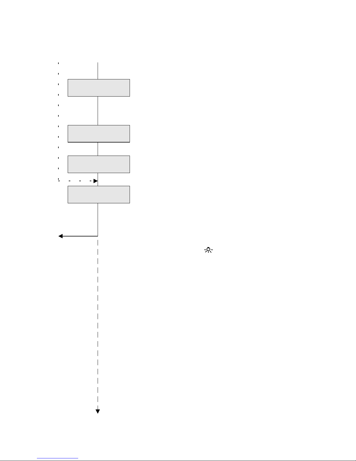
9 Switching LED 4, continued
9.05 Porter’s function is active ∗1)
If a porter’s group is activated, LED 4 is illuminated.
Tip:
If one of the 4 porter’s groups are activated, the LED is
illuminated.
9.06 Call forwarding is active ∗1)
If a call forwarding is activated, the LED is illuminated.
9.07 Doormatic is active
If the doormatic function is activated, the LED is illuminated.
9.08 Reversing the display function
The LED display is inverted, i.e. the LED is switched-off
when a function is active, however, it is illuminated when a
function is passive. In this way, e.g. reporting functions
which are based on the door-opener function can be
inverted.
to pos. 9.01
Enabling areas/functions
menu
⇒ Exit to start with .
LED 4 Follow me
Y=1/N=0 0
LED 4 Caretaker
Y=1/N=0 0
LED 4 Doormatic
Y=1/N=0 0
LED 4 display
inverse Y=1/N=0 0
Page 23
22
HT 644-02
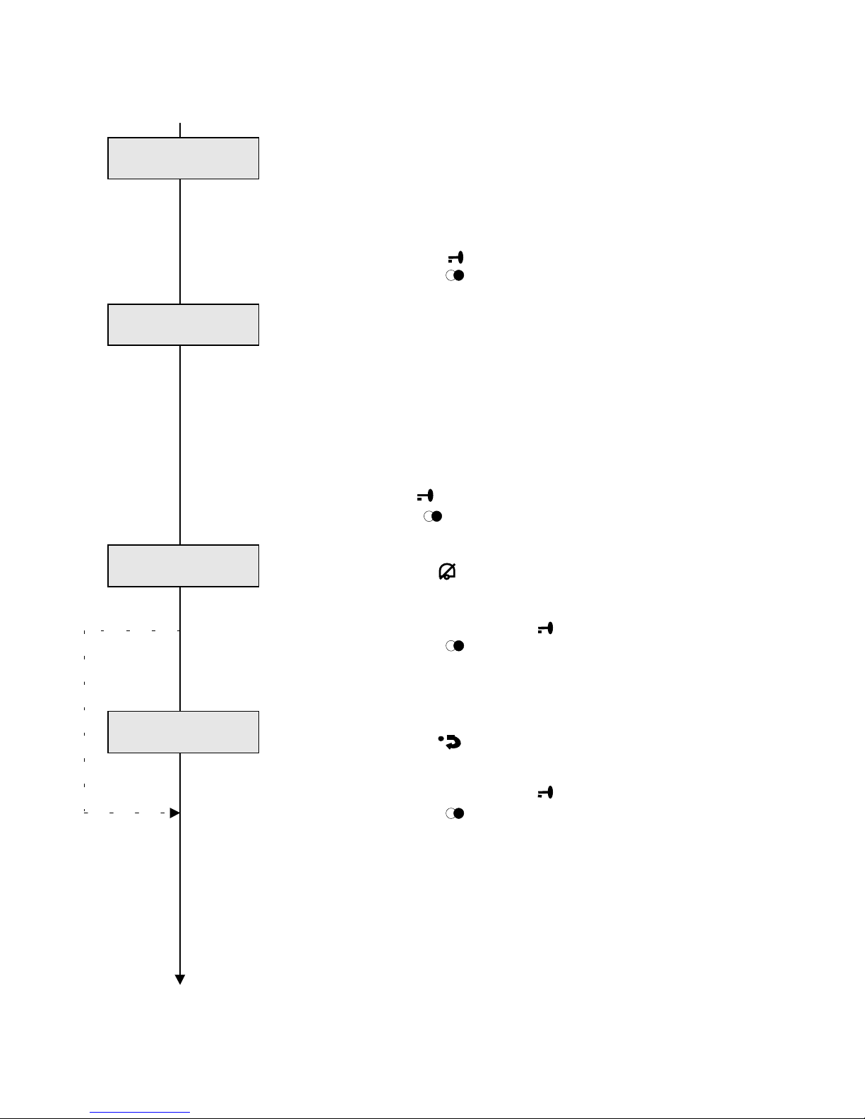
10 Enabling/disabling Keys or functions
Various functions, especially the functions of the control keys
on the HT 644 unit, as well as particular teleswitching
functions, can be both individually enabled (released) and
disabled (barred) for the subscriber.
⇒ Open menu with
or continue with
.
10.01 Enabling remote switching functions
The remote switching functions 1 - 8 can be both enabled
(released) and disabled (barred), however, only one function
at the same time. The enabled functions are displayed as
digits, however, disabled functions are displayed as a "–".
⇒ Enter the number of the function which must be edited:
If display screen changes to the respective digit: function is
enabled (released)
If display screen changes to "
–
": function is disabled (barred)
⇒ confirm with
or continue with
.
10.02 Enabling or disabling call-barring
The function of the key (call-barring) can be enabled or
disabled.
⇒ Release with "1", confirm with
or continue with
These menu items are only available in Stage-2 systems.
10.03 Enabling the call-diversion function ∗)
The function of the key (call diversion) can be enabled
(released) or disabled (barred).
⇒ Release with "1", confirm with
or continue with
.
Please note:
Menu items marked with ∗) are only available in Stage-2
systems.
continue at “Keys / functions"
Keys / Functions .
en/dis. with <OK>
Remote fct.
1-8
1 2 3 4 5 -- -- 8
Call silencing
EN=1/DIS=0 1
Rerouting
EN=1/DIS=0 0
Page 24
23
Programming-
instruction
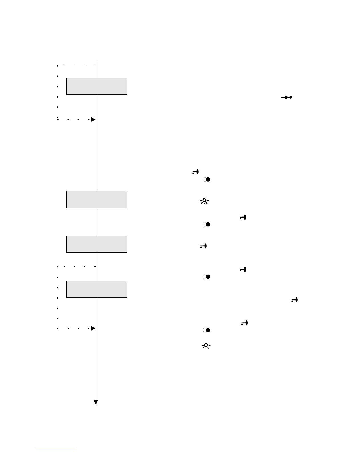
10 Releasing/barring Keys or functions, continued
∗)
10.04 Concierge (caretaker) groups ∗)
Up to a maximum of 4 porter’s groups can be
activated/deactivated through a HT 644-.. unit. ( key).
For each HT, the authorization of each single concierge
group can be individually enabled (released) or disabled
(barred).
⇒ Enter the number of the function which must be edited:
If display screen changes to the respective digit:
function is enabled (released)
If display screen changes to "−":
function is disabled (barred)
⇒ confirm with
or continue with
10.05 Releasing / barring the light key
The function of the light key can be released or barred.
⇒ Release with "1", confirm with
or continue with
.
10.06 Releasing / barring the door-opener key
The function of the door-opener key can be released or
barred.
⇒ Release with "1", confirm with
or continue with
.
10.07 Releasing / barring the doormatic function ∗)
The doormatic function is enabled through the ( F + )
function, can be released or barred.
∗)
⇒ Release with "1", confirm with
or continue with
⇒ Exit to start with .
Please note:
Menu items marked with ∗) are only available in Stage-2
systems.
Barring or releasing of functions exclusively effects the
desktop of the HT 644-.. unit.
Functions which are allocated to MFM-611-10 keys are not
affected by the above specified settings.
Set clock menu
Licht button
EN=1/DIS=0 0
Door release
EN=1/DIS=0 1
Doormatic
EN=1/DIS=0 0
Caretaker 1-4
EN/DIS 1 2 -- --
Page 25
24
HT 644-02
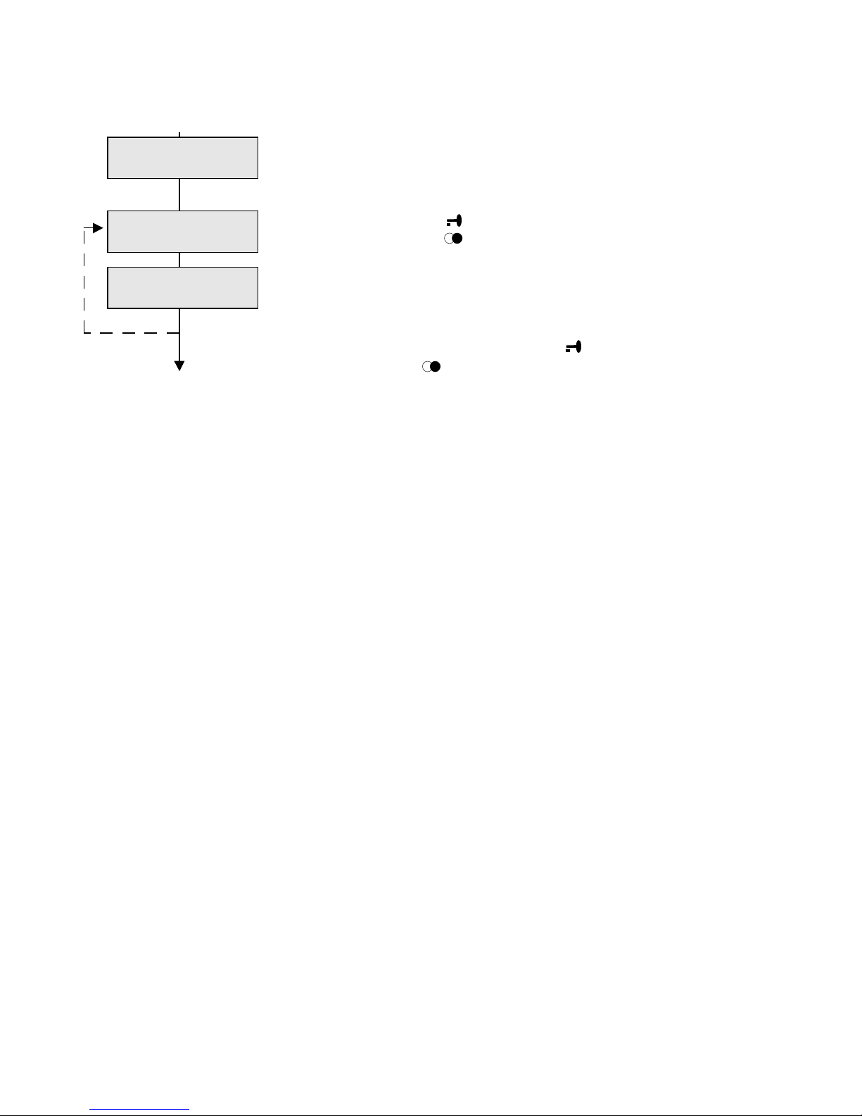
11 Setting the system clock
The HT-644-.. unit has a clock function. Time indication can
be released, and the time is shown in the display screen.
⇒ Open menu with
or continue with
.
The time can either be synchronized through a system
clock (if available in the system) or is manually set (any
power failure switches-of the clock!).
Enter through keyboard, confirm with
or continue with
Service menue
Set clock
with <OK>
Set clock
manually _ _:_ _
Set clock
using sys.. _ _:_ _
Page 26
25
Programming-
instruction
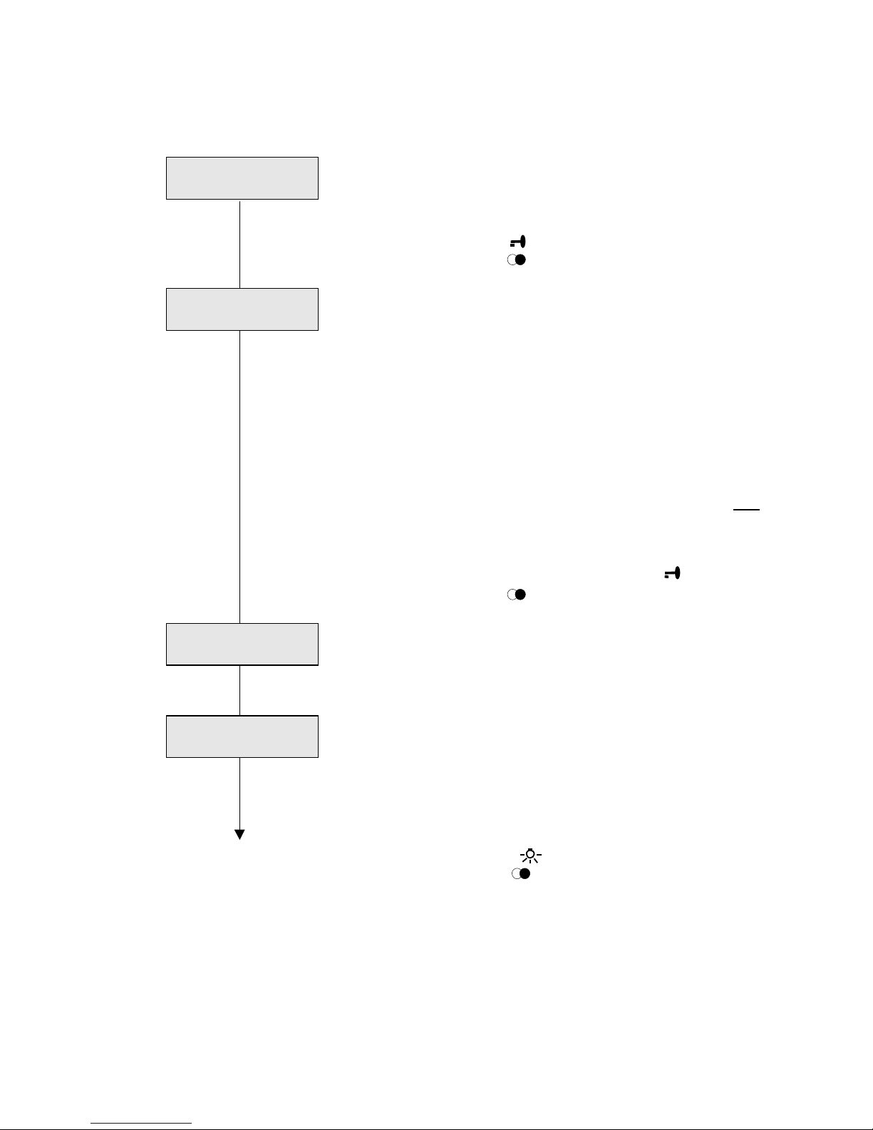
12 Service menue
This menue contains several functions for commissioning
and troubleshouting.
⇒ Open menu with
or continue with
.
12.01 Initializing
Important status information of all units of the system is
queried and, if required, saved in the particular units in the
configuration memory (e.g. group assignment, type of unit,
functional basic settings, etc.).
When initializing, the subscriber-number-allocation list
which is stored in the triggering HT 644.. unit is transmitted
to the system bus, and this list is both received from and
stored in all other units, if enabled (released) accordingly.
(please, refer to subscriber-number-allocation menu)
Each time when commissioning-up the system for initial
operation, or after editing the system configuration, one
(freely selectable) HT 644- unit can perform the initialization
in principle.
⇒ Start initialization with "1", confirm with
or continue with
.
Initialization run
All unit addresses are automatically called. In response,
each existing unit reports its status. The left side of the
display screen shows the currently called address, and the
right side the number of found units.
Very important:
Initializing must be performed after both installing the
units and allocating the addresses, resp. after
configurating all connected units, and it must be newly
executed after each modifying or supplementing.
⇒ Exit to begin with .
next menue with
.
set default
Service menue
with <OK>
Initialize
system with <OK>
Please wait
Addr. 099 8
Initia. complete
8 units
Page 27
26
HT 644-02
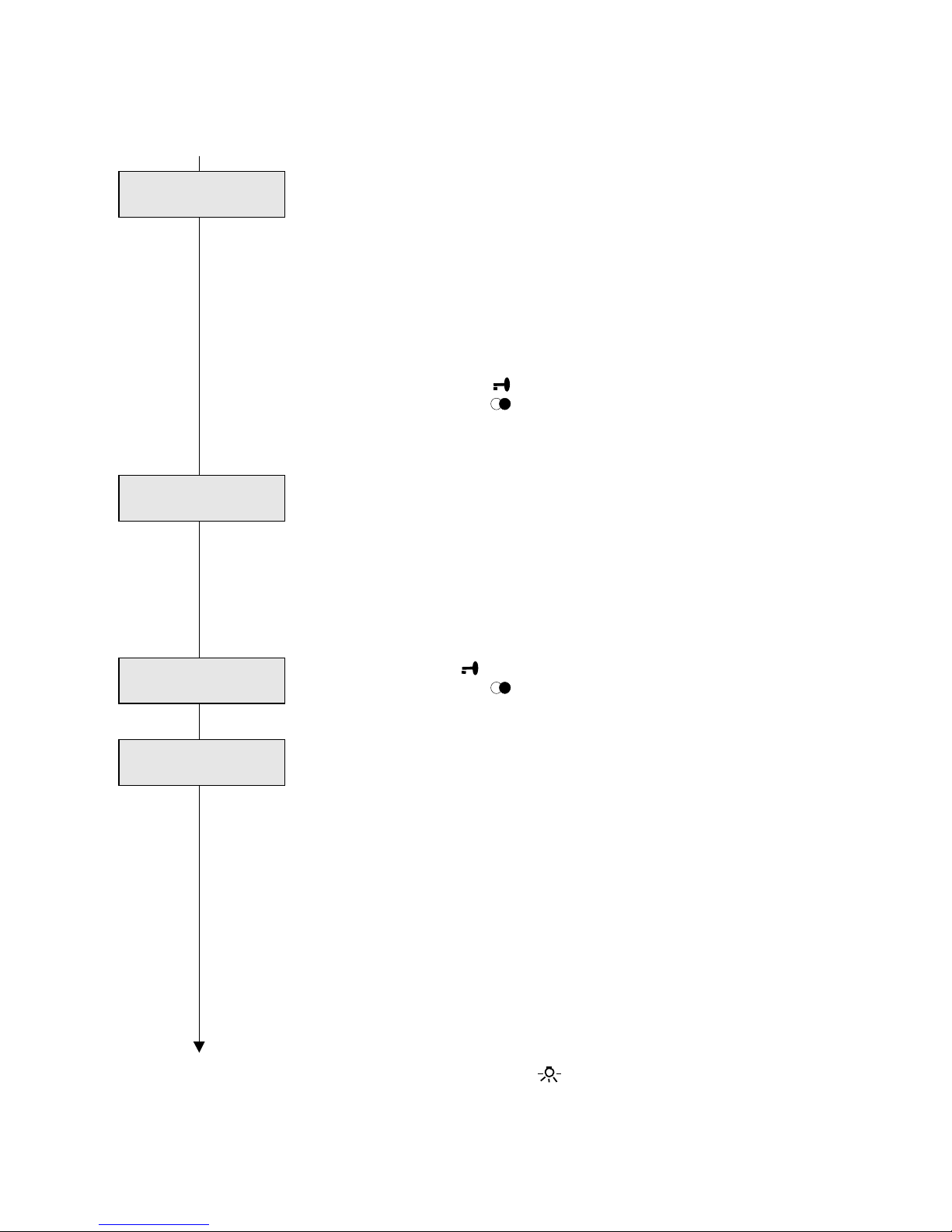
12.02 Set default
The HT 644-02 can be reseted to the delivery state.
All individually configured features will be set to the default
conditions.
Tip:
It´s recommended, to use this function, if the HT 644 has
malfunctions, witch are not comprehensible or after
installation an used, configured HT in a new system.
Then reconfigure the unit new.
⇒ start setting with
or continue with
12.03 Displaying the data traffic
This function accomplishes service purposes. The last two
data protocols transmitted on the system bus are shown in
hexadecimal format in the display screen.
In this way, simple functional tests or functional tests of the
data transmission can be performed, if the "SEMTEST"
system-test unit or the service logging printer are not
available.
⇒ Release with
or continue with
.
Displaying format
The last two data protocols are shown in the 8-digit
hexadecimal format, as well as information whether the
receiver confirmed the transmitted data protocol (Y), or
whether it did not confirm (N).
Well-founded knowledge of the data-format content is
required for the evaluation.
(please, refer to the instruction regarding: "Malfunction
finding in Multi systems")
Application examples
- Testing the function or unit address of a unit
- Testing function, address, and allocation of the calling key
of a door loudspeaker
- Testing the general activities of a unit
End of programming
⇒ Exit to main menu with .
Exit to normal operation: Hang-up the handset.
Show data transf.
with <OK>
Set default
with <OK>
Data transfer
Data transfer
45590009 Y
A5500009 N
Page 28

27
Programming-
instruction
Further Informations
– HT 644-02 Product information
– HT 644-02 Operating instruction
– Siedle-Multi-Systemdokumentation and planning guide
Please use the form "HT 644-02 programming list" for the documentation of the individually
configuration and enclose this the system documentation.
The agreed function of the HT 644-.. you can find at the functional description into our special
tender, the unit address and group no. you can find into the system- and cable running plan, or
the enclosed address/ call no. list of the system documentation.
For further informations please contact your Siedle Service center or direct the Electronic
special departement (Elektronischer Sonderbau).
Page 29

Electronic special department
S. Siedle u. Söhne
Telefon- und Telegraphenwerke
Stiftung & Co
Post box 1155
78113 Furtwangen
Bregstraße 1
D 78120 Furtwangen
Telefon ++49 7723/63-378
Telefax ++49 7723/4573
 Loading...