

Page 1
System Manual
In-Home bus: Video
Issue 2007
Page 2

Contents
1 In-Home bus: Video
System description 3
2 Safety remarks 3
3 Configuration,
conductor lengths
Single line system 4-5
Single line system
with bus distributor 6-7
Multiple line system 8-9
Calculation example 10
Installation with J-Y(ST)Y 11
Increased range
operating mode 11
Bus distributor 12-13
4 In-Home: Video users
Bus door loudspeaker,
call buttons,
bus video transmitter 14-15
Bus camera and accessories 16
Transformer, bus distributor 17
Power supply, line rectifier 18
Switching and control functions 19
DoorCom, PC interface 20
Bus telephones Audio 21
Bus telephones Video 22
Accessories 23
Table top accessory 24
5 Video installation
Wiring diagrams AS
Bus call button module,
Bus video line rectifier 25
AS-TVHa-1/1 Siedle Vario 26
AS-TVHa-1/1 Siedle Vario with
bus distributor BVVU 650-... 28-29
AS-TVHa-1/1
Siedle custom-fit
door loudspeaker 30
AS-TVHa-1/1 Siedle Classic 32
AS-TVHa-1/1 Siedle Steel 34
AS-TVHa-1/2 Siedle Vario
2 door stations 36
AS-TVHa-2/1 Siedle Vario
Multiple line system 38
22
AS-TVHa-1/1 Siedle Vario
Calling via display call module 40
AS-TVHa-1/1 with Siedle Vario
DoorCom Analog DCA 650-... 42
AS-TVHa-1/1 with Siedle Vario
Additional external camera 44
6 Audio & video installation
Wiring diagrams AS
AS-TVHa-1/1 Siedle Vario 46
AS-TVHa-1/2 Siedle Vario
2 audio & video door stations 48
AS-TVHa-2/1 Siedle Vario
Multiple line system
Audio & video 50
7 Programming - manual
Overview of functions 52
Remarks 54
Programming - manual
(Teach-In) 55
Door call to BTSV/BTCV 850-... 58
Door call to BTSV 850-... 59
Door calls via the storey
call button 60
Door calls to several
bus telephones 61
Internal calls 62
Dialling the door station 64
Call differentiation between
2 doors 65
Additional contact on the
BSM 650-... 66
Button of a bus telephone
on the BSM 650-... 67
Call button of a door station
on the BSE 650-... 68
Button of a bus telephone
on the BSE 650-... 69
Bus secondary signalling unit
BNS 750-... 70
Door call via the display
call module DRM 611-... 71
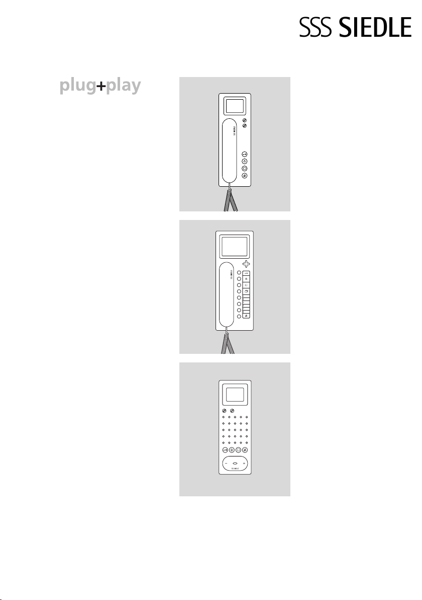
Programming - Plug+Play
Basics 72
Programming - with PC
BPS 650-... and PRI 602-... USB 76
8 Supplementary functions
Switching and control functions 77
AS-TVHa-1/1 with switching
and control functions 78
Door release actuation 80
Parallel door call,
supplementary power supply,
video memory 82-83
Storey call parallel switching 84
Bus secondary signalling unit
BNS 750-... 84
Supplementary contact
for radio chime 85
Pilfer safeguard 85
Staircase/outside light 86
9 Servicing
As-delivered status
Power-On reset 87
Exchanging bus telephones 87
Exchanging BVSG 650-... 87
Operating modes 1-Norm-2 88
LED displays BVNG 650-0 89
Measured values 90
10 Glossary, index 91
The latest edition of the
System Manual In-Home bus:
Audio System Manual
In-Home-Bus: Video System
are located in the
Manual
download area of www.siedle.de
and
Page 3

1 In-Home bus: Video
System description
Siedle-In-Home: Video
single line system
Configuration
The In-Home bus: Video features the
same basic structure as a SiedleIn-Home bus: Audio installation.
Here too, the installation comprises
a two-core line. The essential
difference to the In-Home bus:
Audio is supplementary transmission
of the video signal to the cores.
Up to 31 different users can be
connected, e.g. bus telephones with
video, door stations or devices for
switching and control functions.
Technically speaking, one device can
encompass several users.
If the building installation permits,
installation can be performed
between one bus telephone with
video and the next bus telephone
with video. If the building
installation does not permit looping
through between bus telephones,
additional bus video distributors
must be used. Without a bus video
distributor, no nodes or branches are
permissible in the line.
In order to connect more than 31
users, several Siedle-In-Home: Video
lines must be connected together.
Installation and programming
In their as-delivered status, the
devices are initially unprogrammed.
After initially switching on the bus
video line rectifier, each of the
connected devices in the line is
assigned its own unique address.
Once installation is complete, a
mutual "teach-in" process between
all the devices must be performed to
ensure that functions are correctly
executed (e.g. the bus telephone
rings as soon as the call button is
pressed).
Siedle-In-Home: Video
multiple line system
Configuration
In-Home: Video single line system is
restricted to 31 users; In order to
connect more than 31 users, up to
15 lines can be coupled together.
Each line requires its own bus video
line rectifier BVNG 650-0.
Installation and programming
The bus video line rectifiers are
connected via two separate cores to
link the individual lines. Different
addresses must be set at the bus
video line rectifiers using the rotary
switch.
Programming of the multiple line
system can be compared to the
single line system.
Mounting, installation and
servicing work on electrical
devices may only be performed
by a suitably qualified electrician.
Failure to observe this regulation
could result in the risk of serious
damage to health or fatal injury
due to electric shocks.
When working at the device,
•
observe the remarks relating to
mains cut-off.
• Observe the standard DIN
EN 60065!
When establishing the electronic
connection, observe the
requirements of VDE 0805/
EN 60950.
• The building installation must
feature an all-pole mains switch with
a contact opening of at least 3 mm.
• Ensure that the connection point
in the building installation is fused
with max. 16 A.
• When planning large-scale
(complex) systems, the distributor
space required for the switch panel
mounting devices must be taken
into consideration in the distributor
planning process.
• No external voltages
>30 V AC/DC may be applied to bus
users.
Devices with 230 V connection
In accordance with DIN VDE 0100
part 410, section 411.1.3 attention
must be paid to ensuring a safe
separation between bus lines and
the mains voltage; i.e. bus and
mains cores must not be permitted
to touch! The bus line cable (extralow safety voltage) must be stripped
back by the minimum possible.
33
Page 4
3 Configuration, conductor
lengths in single-line systems
Configuration of In-Home: Video
The basic Siedle-In-Home bus
installation type is the single line
system. Within this one line,
installation takes place from one
device to the next, provided this is
allowed by the building installation.
In buildings with a side circuit and
individual branches into the
apartments, the bus video distributor
must be used. A maximum of 31
users are admissible within any one
line. Users are defined as devices
which occupy their own address
within the bus. If more than 31 users
are required, additional lines must
be configured. With only a few
exceptions, all devices are assigned
an address. Up to 15 lines with 31
users each can be configured.
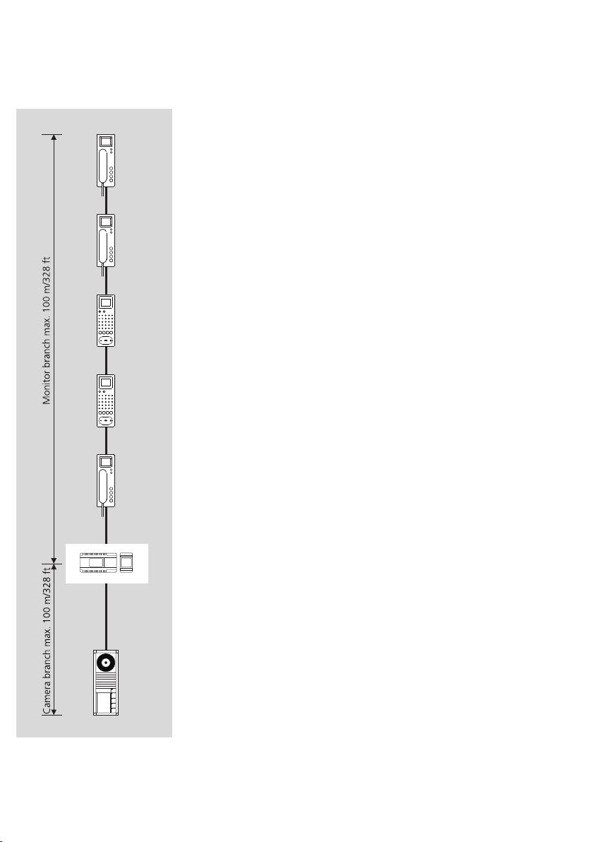
Camera branch and monitor
branch
Within a line, a distinction is made
between the camera branch and the
monitor branch. Video door stations
are connected to the camera branch,
while bus telephones with video are
connected to the monitor branch. If
the installation requires an additional
monitor branch, so-called bus
distributors must be used.
Users without video
In the case of In-Home: Video, audio
users can only be connected via a
bus audio decoupler BAA 650-... .
Switching and control devices are
also connected to the BAA 650-... .
Power supply
The nerve centre of every line is the
bus video line rectifier, which
controls all the system functions. The
camera branch and monitor branch
are connected to it via separate
terminals.
Conductor material
Telecommunication or light current
conductors can be used for
installation:
J-Y(ST)Y twisted pair
conductors, shielded
44
A2Y(ST)2Y buried
telecommunication
cable
YR light current conductor
Core diameter
0.8 mm
The In-Home bus must be installed
on one pair of cores for J-Y(ST)Y
conductors, on two adjacent cores
for YR conductors.
Using J-Y(ST)Y conductors reduces
the likelihood of interference.
Conductor length
Conductor material YR cable with
0.8 mm diameter:
• max. 100 m from the bus video
line rectifier to the most distant user
in the monitor branch
• max. 100 m from the bus video
line rectifier to the most distant user
in the camera branch
With a core diameter of 0.6 mm, the
range is halved.
Within the line, the maximum
length of the conductor material
must not exceed 1,500 m.
When using J-Y(ST)Y conductor
material, longer ranges can be
achieved. Installation using J-Y(ST)Y
is described in detail on page 11.
When installing, ensure without fail
that the camera branch and monitor
branch are not laid in the same
cable. Forward and return lines to a
bus telephone with video must not
be laid in the same cable.
Otherwise, picture disturbance may
result.
If installation from one bus
telephone to the next bus telephone
is not possible, bus distributors must
be used. In this case, attenuation of
the conductor material and bus
distributors must be additionally
taken into consideration.
Terminating resistor
Transmission of signals within SiedleIn-Home: Video takes place using
high-frequency technology.
In order to avoid disturbance on the
bus cores, the end of each monitor
branch must terminated with an RC
Page 5
element. The RC element comprises
a resistor with 100 Ohm and a
capacitor with 1 nF. In its asdelivered status, each bus telephone
with colour monitor has a small
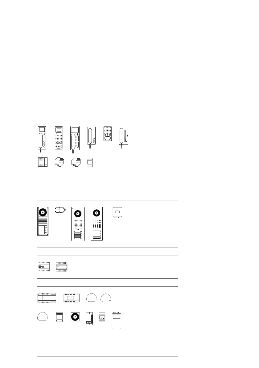
In-Home bus users: Video
Overview of user assignment of the
individual devices
Devices occupying 1 user
Devices occupying 2 users
fitted circuit board with this
terminating resistor at output
terminals TaM/TbM.
BTSV 850-...
BFSV 850-...
BTCV 850-...
BTS 850-...
BFS 850-...
BTC 850-...
BNS 750-...
BSE 650-...
BEM 650-...
BSM 650-...
BTLM 650-03
BTLE 050-03
CL V xx B-01
STL ...
BVA 650-...
Devices with variable user assignment (depending on programming)
DCA 650-...
DCI 600-...
Devices occupying no users
BNG 650-...
BVNG 650-...
BAA 650-...
BVVU 650-...
BVVS 650-...
BIM 650-...
BCMC 650-...
BRMA 050-...
PRI 602-... USB
BVS 650-...
55
Page 6

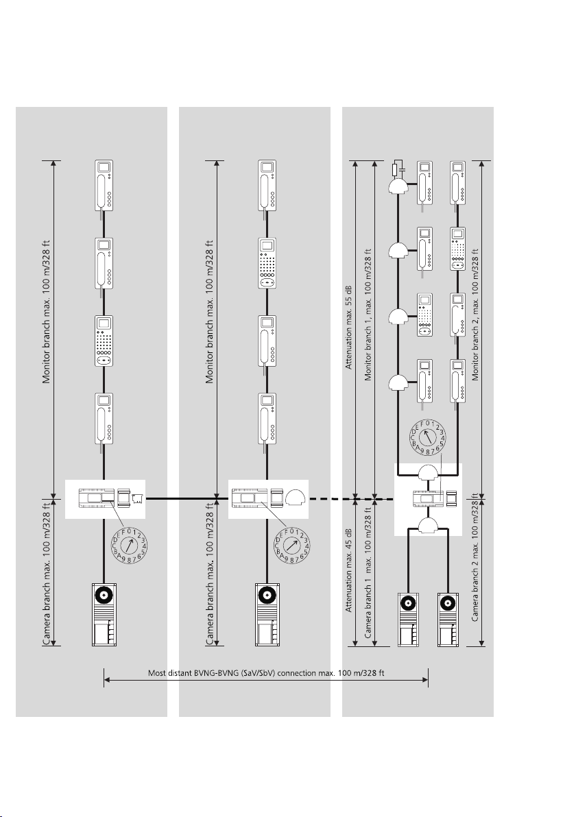
3 Structure, conductor lengths single line system
with bus distributor
Conductor length with bus
distributor
If the use of bus distributors is
necessary for installation, in addition
to the maximum range, attenuation
of the bus distributors and
conductor material must be
additionally taken into account.
The following information relating to
conductor lengths refers to one
camera branch and one monitor
branch. If several branches are
installed within a line, the
information is applicable to each
branch.
Whichever value (attenuation or
conductor length) is reached first is
applicable as a specification of the
admissible value.
Maximum conductor length
Conductor material YR cable with
0.8 mm diameter:
• max. 100 m from the bus video
line rectifier to the most distant user
in the monitor branch
• max. 100 m from the bus video
line rectifier to the most distant user
in the camera branch
• max. 45 dB attenuation from the
most distant user in the camera
branch to the most distant user in
the monitor branch
With a core diameter of 0.6 mm, the
range is halved.
Signal transmission
Only signals from the In-Home bus
may be transmitted over the laid
conductor material. No additional
transmissions, for example PBX
extensions of a telephone system,
S0 Bus (ISDN) or data lines of an
alarm system in the same cable.
The camera branch and monitor
branch must be laid separately and
must not be located in the same
cable. This can result in disturbance
to the picture composition.
Terminating resistor
Transmission of signals within SiedleIn-Home: Video takes place using
high-frequency technology.
In order to avoid disturbance on the
bus cores, the end of each monitor
branch must terminated with an RC
element.
The RC element comprises a resistor
with 100 Ohm and a capacitor with
1 nF. In its as-delivered status, each
bus telephone with colour monitor
has a small fitted circuit board with
this terminating resistor at output
terminals TaM/TbM.
The maximum admissible
attenuation is 45 dB within a
line. General rule for YR cable
material with 0.8 mm diameter:
10 m conductor length
corresponds to 2 dB attenuation!
The maximum length of the
conductor material to be laid within
the line is 1,500 m.
If the maximum admissible
attenuation of 45 dB is exceeded,
the bus video line rectifier accessory
ZBVNG 650-0 must be used in the
BVNG 650-... to compensate for this
loss.
6
Page 7
3 Configuration, conductor lengths
Single line system with bus distributor and ZBVNG 650-0
Conductor length with bus
distributor and ZBVNG 650-...
The ZBVNG 650-... accessory
amplifies the video signal, so
permitting greater attenuation in the
camera branch and monitor branch.
To do this, the inserted jumper card
in the BVNG 650-... is removed and
the ZBVNG 650-... inserted in the
same slot.
The following information relating to
conductor lengths refers to a camera
branch or monitor branch. If several
branches are installed within a line,
the information is applicable to each
branch.
Whichever value is reached first is
applicable as a specification of the
admissible value.
The limiting values must be adhered
to for each of the branches.
Maximum conductor length
Conductor material YR cable with
0.8 mm diameter:
• max. 100 m from the bus video
line rectifier to the most distant user
in the monitor branch
• max. 100 m from the bus video
line rectifier to the most distant user
in the camera branch
• max. 45 dB attenuation from the
bus video line rectifier to the most
distant user in the camera branch
• max. 55 dB attenuation from the
bus video line rectifier to the most
distant user in the monitor branch
With a core diameter of 0.6 mm, the
range is halved.
The maximum length of the
conductor material to be laid within
the line is 1,500 m.
7
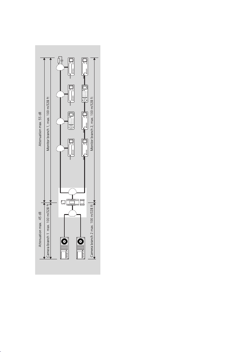
Page 8
3 Configuration, conductor lengths
Multiple line system
Line 1
Line 2
Line 15
8
Page 9

Structure of a multiple line
system
A multiple line system comprises
individual lines which are linked
together by two cores. The lines are
connected at the bus video line
rectifier using terminals SaV and
SbV.
In multiple line systems, speech and
video connections are possible from
one line to another. To generate a
multiple line system, the bus line
rectifier accessory ZBVG 650-... is
required in one of the bus video line
rectifiers. In each bus video line
rectifier, the bus video line rectifier
accessory ZBVNG 650-... is required.
Differentiation between line 1
and line 2 ...
The lines are consecutively
numbered using the address switch
“addr.” at the bus video line rectifier
BVNG 650-... . Up to 15 lines can be
linked via the SaV and SbV cores.
The bus video line rectifier is
connected via the bus distributor
BVVU 650-...
At the bus video line rectifier, a bus
line rectifier can be connected
directly via the cores Sa and Sb in
order to link a line with In-Home:
Audio. During installation, ensure
that each line is laid in a separate
cable.
Conductor length between the
lines
The admissible conductor lengths
within a line are identical to those in
a single line system. In addition, the
admissible conductor length
between the bus video line rectifiers
must be taken into account.
This must be no more than 100 m
between the most distant bus video
line rectifiers (YR cable with
0.8 mm diameter).
In a multiple line system comprising
only 2 lines, connection between the
two bus video line rectifiers is
possible without bus distributor
BVVU 650-... .
The maximum admissible lengths
within a line and the attenuation
values continue to be valid.
When installing, ensure without
!!
fail that the camera branch and
monitor branch are not laid in the
same cable.
Forward and return video signal
looping must each be laid in a
separate cable.
Otherwise, picture disturbance may
result.
Functions applicable across
individual lines
Door calls, selective door dialling and
switching and control functions can
also be used across individual lines.
Internal speech communication and
call forwarding between users is only
possible within a line.
9
Page 10
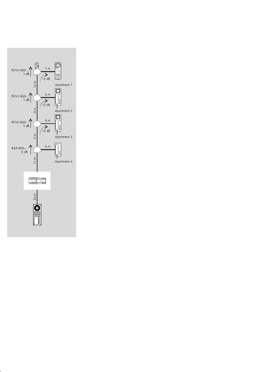
3 Configuration, conductor lengths
Example to determine the attenuation
Example to determine the
attenuation with bus distributor
The system is installed using YR
cable 0.8 mm diameter. This means
that 10 m of conductor length have
an attenuation of 2 dB. Apartment 4
is decoupled using a bus audio
decoupler BAA 650-... , apartment
1 - apartment 3 are connected via
bus video distributor BVVU 650-... .
Attenuation in the camera
branch
Conductor length between the door
station and the sub-distributor 25 m.
25 m = 5 dB
Attenuation in the monitor
branch to apartment 3
Conductor length of the installation
cable. All values added, from the bus
video line rectifier to the bus
telephone:
11 m + 4 m + 5 m = 20 m
20 m conductor length corresponds
to 4 dB attenuation!
Attenuation of the bus distributor
BVVU 650-... = 12 dB
Total value:
12 dB distributor + 4 dB conductor
= 16 dB
This means that apartment 3 has a
total attenuation from the camera to
the bus telephone of 16 dB + 5 dB
= 21 dB
Attenuation in the monitor
branch to apartment 1
Conductor length of the installation
cable. All values added, from the bus
video line rectifier to the bus
telephone:
11 m + 4 m + 4 m + 12 m + 7 m
= 38 m
38 m of conductor material add up
to 7.6 dB
Attenuation of all bus distributors:
1 dB + 1 dB + 12 dB = 14 dB
Total value:
14 dB distributor + 7.6 dB conductor
= 21.6 dB
Apartment 1 has a total attenuation
from the camera to the bus
telephone of 21.6 dB + 5 dB
= 26.6 dB
The maximum value with this
example would be 26.6 dB from the
most distant video door station to
the most distant bus telephone, the
maximum admissible would be
45 dB.
With greater attenuation over 45 dB,
accessory ZBVNG 650-... can be
used to increase attenuation in the
camera branch to 45 dB and in the
monitor branch to 55 db.
On the following double page, the
precise function of the bus
distributor is explained in detail.
10
Page 11
3 Configuration, conductor lengths
Installation with J-Y(ST)Y, increased range
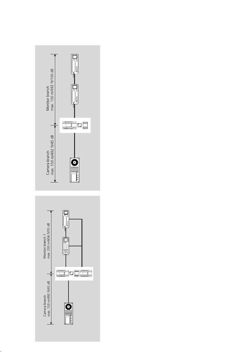
Installation with J-Y(ST)Y
The ZBVNG 650-... must be plugged
into the BVNG 650-...!
In deviation from the range
specification in standard systems
with YR cable material, when using
J-Y(ST)Y with 0.8 mm an increased
range is possible.
Conductor material J-Y(ST)Y cable
with 0.8 mm diameter:
• max. 150 m from the bus video
line rectifier to the most distant user
in the monitor branch
• max. 150 m from the bus video
line rectifier to the most distant user
in the camera branch
Increased range operating mode
The ZBVNG 650-... must be plugged
into the BVNG 650-...!
When using cable material J-Y(ST)Y
with 0.8 mm, it is possible to
increase the distance from the bus
video line rectifier to the bus
telephones with colour monitor. In
this case, each bus telephone with
colour monitor must be provided
with an additional power supply
(e.g. video line rectifier VNG 602-0).
At the bus video line rectifier
BVNG 650-... the
switch must be set to 2
Conductor material J-Y(ST)Y cable
with 0.8 mm diameter:
• max. 200 m from the bus video
line rectifier to the most distant user
in the monitor branch
operating mode
.
If it is necessary to use bus
distributors within the installation,
the attenuation of the conductor
material and the bus distributor
must be taken into consideration.
With a core diameter of 0.6 mm, the
range is halved. Installation is also
possible in a multiple line system
with 0.8 mm conductor material.
Installation must take place as a bus
installation, not in star formation.
In a multiple line system this
facility can be used to increase the
range in every line.
In the case of a parallel call to
several bus telephones with video,
the admissible conductor length of
the power supply must be noted. For
more information on supply and
parallel switching, see Chapter 8,
page 82.
The following still applies within any
one line: The maximum length of
the conductor material must not
exceed 1,500 m.
Installation is also possible in a
multiple line system with 0.8 mm
conductor material. Installation must
take place as a bus installation, not
in star formation.
11
Page 12
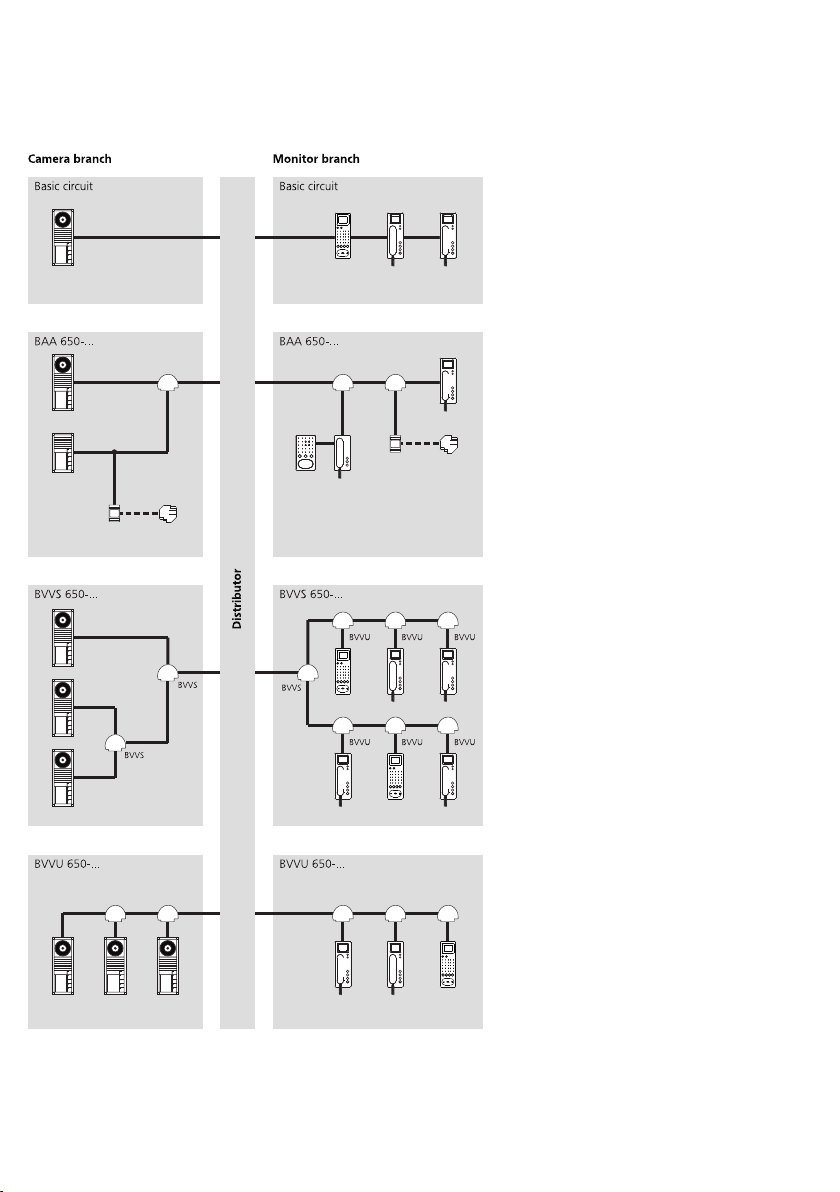
3 Configuration, conductor lengths
Bus distributor application
Camera branch: No bus distributor
required with a door station.
Monitor branch: No bus distributor
required when looping through from
bus telephone to bus telephone. The
integrated bus distributor in the bus
telephones is used.
Attenuation: No attenuation to be
considered.
BAA 650-... in the camera branch:
Connection of audio users (e.g.
BTLM 650-... or BTLE 050-...) or
users for switching and control
functions.
BAA 650-... in the monitor
Connection of audio users
branch:
(BTS/BFS/BTC 850-..., DCA 650-...)
or users for switching and control
functions.
Attenuation: No attenuation to be
taken into consideration if
decoupled.
BVVS 650-... in the camera branch
More than one video door station in
the camera branch with “star
shaped” conductor routing.
BVVS 650-... in the monitor
Within the In-Home bus:
branch:
Video more than one side circuit is
required.
Attenuation: The attenuation from
BVVS 650-..., BVVU 650-... and the
conductor length must be taken into
consideration.
Unconnected looping
ii
terminals in the bus distributor
BVVU 650-... and BAA 650-... must
always be terminated with an RC
element in order to prevent
disturbance to the bus.
12
BVVU 650-... in the camera
branch
More than one video door station in
the camera branch with “loop
through” conductor routing.
BVVU 650-... in the monitor
branch:
Connection of a bus telephone with
monitor to a side circuit with
“looped through” conductor
routing.
Attenuation: The attenuation from
BVVU 650-... and the conductor
length must be taken into
consideration.
Page 13

3 Configuration, conductor lengths
Bus distributor attenuation values
BAA 650-... in the camera branch BVVS 650-... in the camera branch BVVU 650-... in the camera branch
Application
Connection of a door station
without video (e.g. BTLM 650/
BTLE 050) or switching and control
devices (BSE 650, BSM 650,
BEM 650) at the Siedle In-Home bus:
Video.
For a connection example, see
page 48–49.
BAA 650-... in the monitor branch BVVS 650-... in the monitor branch BVVU 650-... in the monitor branch
Application
Connection of pure audio users
(BTS 850-..., BTC 850-...,
DCA 650-...) or users for switching
and control functions (BSE 650-...,
BSM 650-..., BSE 650-...) within an
In-Home video bus.
For a connection example, see
page 46–47.
Application
When more than one video door
station is operated within a camera
branch.
For a connection example, see
page 36–37.
Application
When more than one rising
main/side circuit is required within
the Siedle In-Home bus. At the
outputs, additional distribution is
required via BVVU 650-... or
BAA 650-... Direct device connection
is not admissible.
Application
When more than one video door
station is operated within a line.
Application
Decoupling a video user from a side
circuit into the apartment.
For a connection example, see
page 34–35.
13
Page 14
4 In-Home: Video users Door loudspeakers, call buttons
BTLM 650-03
Bus door loudspeaker module for InHome bus.
Loudspeaker and microphone
integrated, illuminated light button,
integrated door release contact (DR)
contact load max. 15 V AC,
30 V DC, 2 A, switching time DR
fixed at 3 seconds. Acoustic
feedback when actuating the call
buttons.
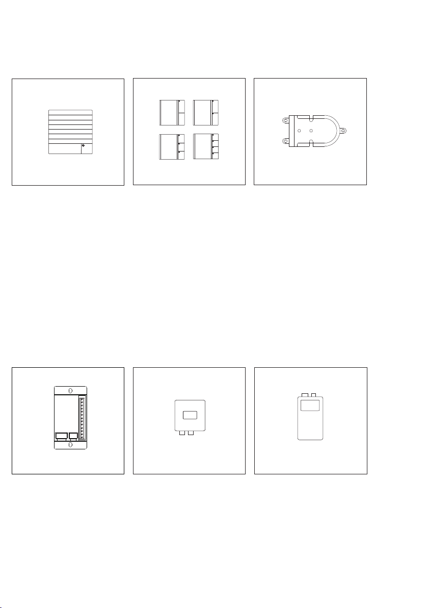
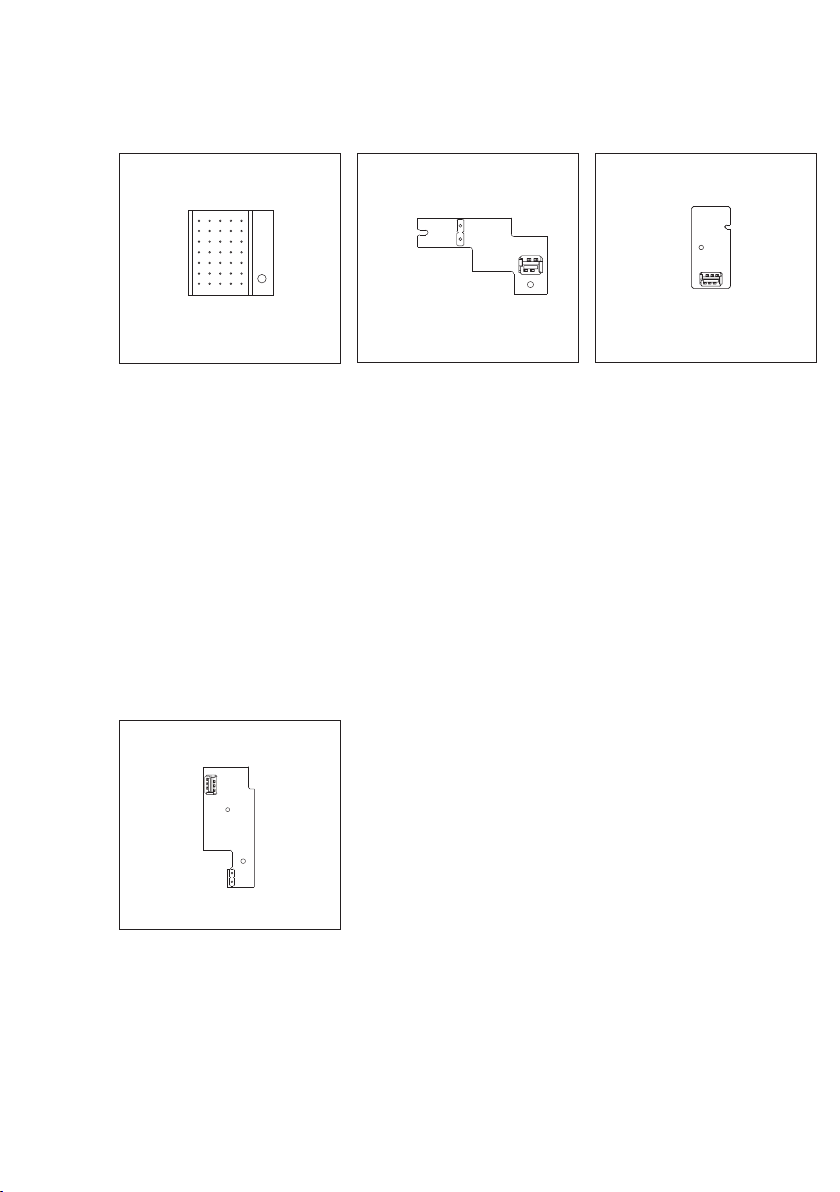
BRMA 050-01
Bus call button matrix for connection
of a maximum of 12 existing on-site
call buttons using screw-type
terminals.
Additional BRMA 050-... units can
be linked in order to connect a
maximum of 160 call buttons to one
bus door loudspeaker.
BTM 650-01 - BTM 650-04
Bus call button modules for In-Home
bus.
1-4 call buttons, integrated LED
lighting. Connection by means of
ribbon cable to the bus door
loudspeaker. The LED lighting is
supplied via terminals b and c with
12 V AC, current consumption
25 mA per bus call button module
BTM 650-...
BVA 650-... AP/UP
Bus video interfacing module for
actuation of external video cameras
without door station. Selective
dialling of the camera from a bus
telephone possible via a
programmed button.
AP = Surface-mounted version
UP = Flush-mounted version
BTLE 050-03
Custom-fit bus door loudspeaker for
In-Home bus. Integrated door
release contact (DR). Max. load
15 V AC, 30 V DC, 2 A. Connection
of existing call buttons (self-cleaning)
via bus call button matrix
BRMA 050-..., switching time DR
fixed at 3 seconds. For optimum
mounting in an existing on-site
communication compartment,
universal mounting adapter
ZTL 051-0 can be used. Acoustic
feedback when actuating the call
buttons.
BVS 650-...
Bus video transmitter in the surfacemount housing with cable glands for
connection of an external video
camera to a bus door loudspeaker. Is
used, for instance, if a modular
camera is not possible or a customfit door loudspeaker BTLE 050-... has
to be equipped with video
surveillance.
14
Page 15

Siedle Classic
CL V 01 B-01 - CL V 04 B-01
Door station with stainless steel
front. Door loudspeaker, illuminated
call buttons and bus camera.
Integrated door release contact (DR),
contact load max. 15 V AC,
30 V DC, 2 A, switching time DR
fixed at 3 seconds. Current
consumption LED lighting for the
bell buttons, 20 mA, 12 V AC each
per button.
Siedle Steel STL...
Door station with stainless steel
front, door loudspeaker, call buttons
and bus camera. Integrated door
release contact (DR), contact load
max. 15 V AC, 30 V DC, 2 A,
switching time DR fixed at 3
seconds. Current consumption LED
lighting for the bell buttons, 20 mA,
12 V AC each per button.
15
Page 16
4 In-Home: Video users
Bus camera and accessories
BCMC 650-...
Bus colour camera module for
Siedle-In-Home bus: Video.
Integrated 2-step heating, day/night
switching, infrared lighting and
video signal converter. Supply via
Siedle In-Home bus: Video, heating
supply 12 V AC, 100 mA.
VNG 602-...
Video line rectifier in a 10-grid
housing.
Primary: 230 V AC, 50/60 Hz
Secondary: 30 V DC, 1.1 A
stabilized.
For additional power supply to
deluxe bus telephones when the
video memory module is used or for
power supply in case of parallel calls.
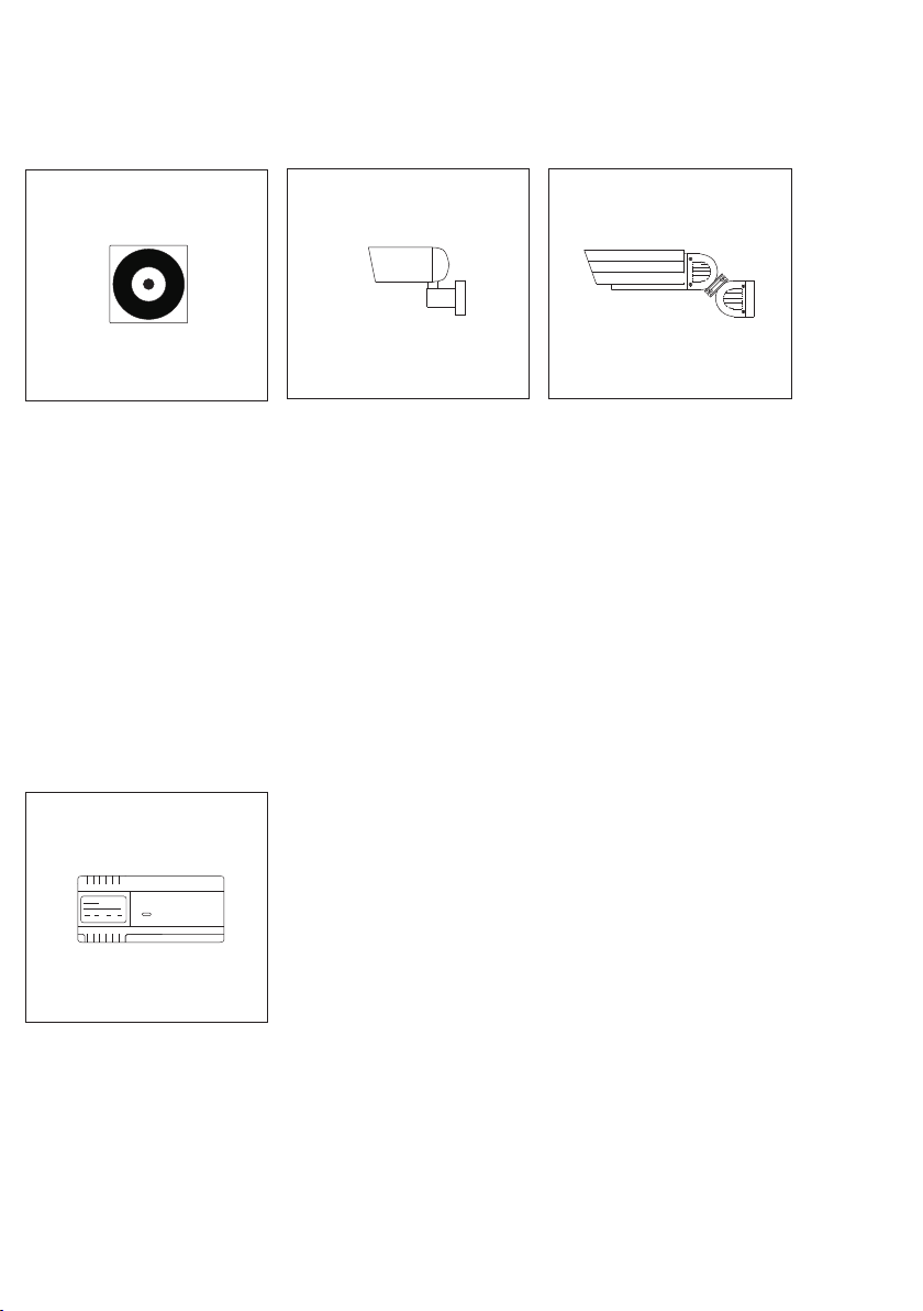
CEC 612-...
External colour camera day/night
CCD video camera for external
mounting in weather proof housing,
wall arm with ball head and internal
wiring.
Connection to In-Home bus: Video
via bus video interfacing module
BVA 650-... or bus video transmitter
BVS 650-... supply via additional line
rectifier, 10,5 - 30 V DC, current
consumption max. 250 mA.
KA/WG 950-... C
External colour CCD video camera
for external mounting with weather
proof housing and sun shade, wall
arm with ball head and internal
wiring.
Connection to In-Home bus: Video
via bus video interfacing module
BVA 650-... or bus video transmitter
BVS 650-... supply via additional line
rectifier, 20 - 30 V DC, current
consumption max. 250 mA.
Using the
accessory
provide a 230 V AC power supply.
line rectifier foot
ZNF 950-0 it is possible to
16
Page 17
4 In-Home: Video users
Bus distributor
TR 603-...
Transformer in a 3-grid housing.
Primary: 230 V AC, 50/60 Hz
Secondary: 12 V AC, 1.3 A
Supply to the LED lighting of the bus
call button module, door release or
heating for the bus camera
BCMC 650-...
BVVS 650-...
Symmetrical bus video distributor for
coupling/decoupling In-Home: Video
users, e.g. for the creation of rising
lines. Screw terminals for bus input
and 2x bus output.
BAA 650-...
Bus audio decoupling for connection
of audio users such as BFS 850-...,
BTS 850-..., BTC 850-..., DCA 650-...
or switching and control devices
within In-Home: Video. Screw
terminals for bus input, looped bus
throughput and connection of audio
users.
BVVU 650-...
Asymmetrical bus video distributor
for coupling/decoupling In-Home:
Video users. Screw terminals for bus
input, looped bus throughput and
bus output.
17
Page 18
4 In-Home: Video users
Power supply, line rectifiers
BVNG 650-0
Bus video line rectifier in a 9-grid
housing.
Primary: 230 V AC, 50/60 Hz, door
release contact 15 V AC, 30 V DC,
2 A, switching time fixed at 3
seconds. Light contact 15 V AC ,
30 V DC, 2 A, switching time
0.4 seconds, modification possible
using bus programming software
BPS 650-...
NG 602-...
Bus line rectifier in a 6-grid housing.
Primary: 230 V AC, 50/60 Hz
Secondary: 12 V AC, 1.6 A and
23.3 V DC - 0.3 A stabilized.
For additional power supply to a
BTSV/BFSV/BTCV 850-... in case of
parallel door calls.
ZBVG 650-0
Bus supply unit accessory for
integration in bus video line rectifier
BVNG 650-... Required for In-Home:
Video with more than one line or PC
programming.
8-pin Western junction box for
connection of the programming
interface PRI 602-0 USB. Only one is
admissible within any Siedle-InHome system.
ZBVNG 650-...
Bus video line rectifier accessory for
mounting in bus video line rectifier
BVNG 650-... is required when
attenuation within a line is more
than 45 dB or for creation of
multiple line systems with more than
one BVNG 650-... In multiple line
systems, the ZBVNG 650-... must be
used in each BVNG 650-...
18
Page 19
4 In-Home: Video users
Switching, control
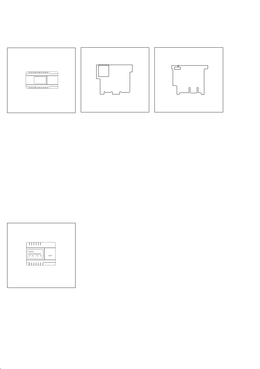
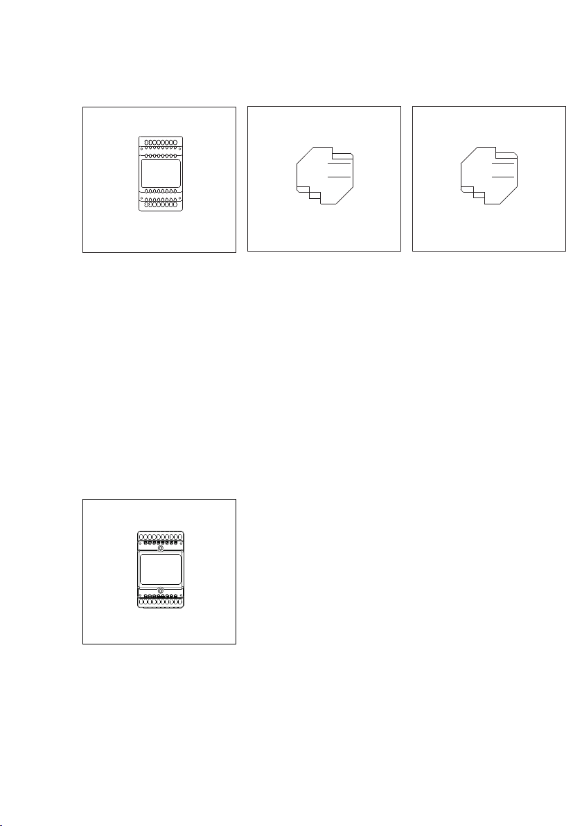
BSM 650-...
Bus switching module in 3-grid
housing. 4 integrated relays, each
with a potential-free working
contact. Actuation via the call
buttons of the bus telephones or
light button at the door station.
Relay function as a timer between
1 secs. and 10 secs. Contact load
max. 15 V AC, 30 V DC, 2 A. Power
supply with 12 V AC, max. 250 mA.
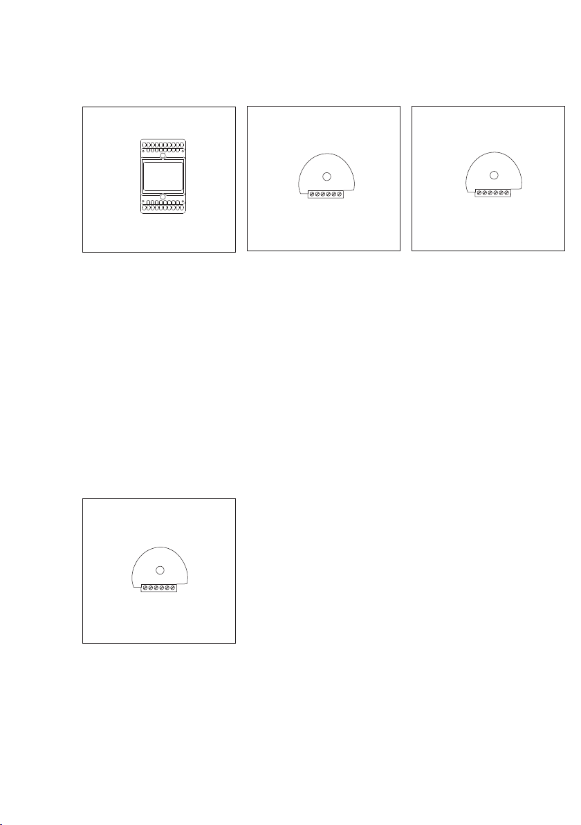
BIM 650-...
Bus interface module in 3-grid
housing. Establishes a connection
between Siedle-In-Home and the
Vario bus.
Is required in order to call bus
telephones via code lock module
COM 611-... or display call module
DRM 611-...
BSE 650-...
Bus switching unit for mounting in
70 mm boxes. LED for status display
and programming mode button.
Actuation using the buttons of the
bus telephones, light button of the
door station or BEM/BSE 650-...
Relay functions as a button, switch,
timer or contact for secondary signal
unit with max. 19 mins. 59 secs.
Contact load max. 250 V AC, 6 A.
BEM 650-...
Bus input module for mounting in
a 70 m box. Input for actuating
switching functions or placing
messages. Input via potential-free
contact or 4 - 30 V DC, 10 mA.
19
Page 20
4 In-Home: Video users
PC interface, DoorCom
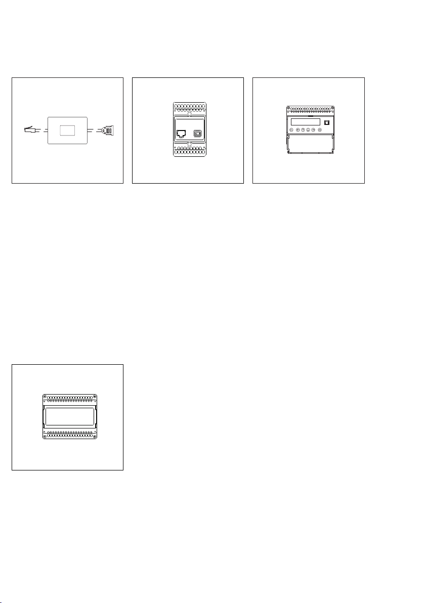
PRI 602-...
Programming interface for
connection of a Windows PC via
serial interface to the Vario bus. The
Vario bus is programmed using
programming software PRS 602-...,
provided with the delivery. If the
BIM 650-... is additionally used, the
In-Home bus can also be
programmed.
DCI 600-0
DoorCom-ISDN for link-up of one or
more door stations to the internal
S0 bus of a telephone system. Up to
31 call numbers can be stored. The
call can be made using bell buttons
or the display call module from the
door station. Power supply with
12 V AC to terminals b/c, connection
to the In-Home: Video only via
BAA 650-...
PRI 602-... USB
Programming interface for
connection of a Windows PC via
USB port to the ZBVG 650-...
interface.
The ZBVG 650-... is plugged into the
bus line rectifier BVNG 650-...
.Commissioning, programming and
servicing facility for the In-Home bus
using BPS 650-... software.
Connection of DCA 650-... and
DCI 600-... to In-Home: Video only
via BAA 650-...
DCA 650-02
DoorCom-Analog for connection of
one or more door stations to an
analogue PBX extension of a
telephone system. Up to 31 call
numbers can be stored.
The call can be made using bell
buttons or the display call module
from the door station. Power supply
with 12 V AC to terminals b and c,
connection to the In-Home: Video
only via BAA 650-...
20
Page 21
4 In-Home: Video users
Bus telephones
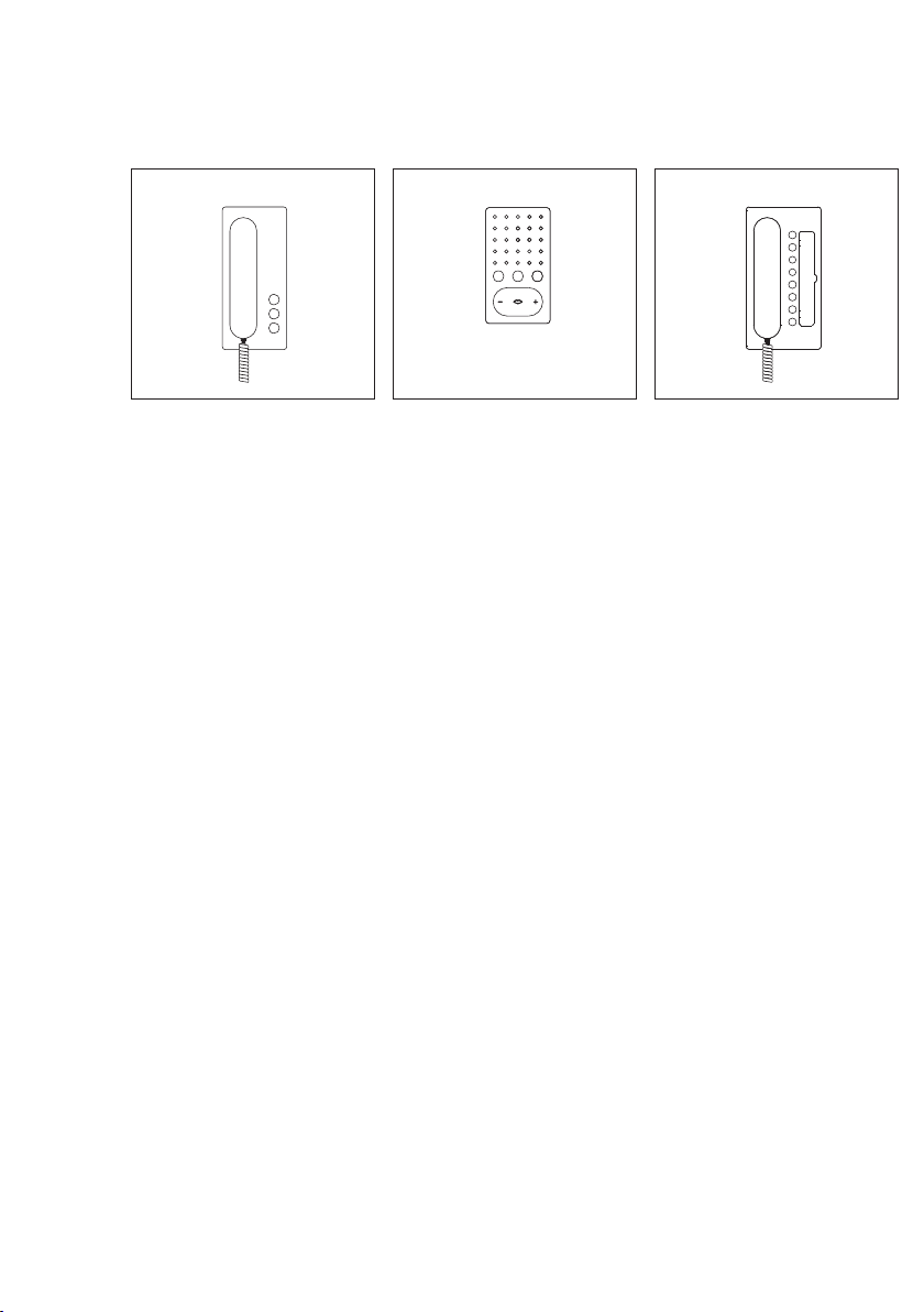
BTS 850-0
Standard bus telephone. Connection
at bus cores Ta and Tb.
• Calling, speech, door release and
storey call
• Door release and light button
• Internal speech communication
• 10 ring tones
• Call and speech volume can be
modified in 5 stages
• Silencing button for the ring tone
• Double assignment of the light
button and silencing button
possible.
• Integration of ZAR 850-...
accessory possible
BFS 850-0
Standard handsfree bus telephone.
Connection at bus cores Ta and Tb.
• Calling, handsfree/push-to-talk
speech, door release and storey calls
• Speech/control button
• Door release and light button
• Internal speech communication
• 10 ring tones
• Call and speech volume can be
modified in 5 stages
• Silencing button for the ring tone
• Double assignment of the light
button and silencing button
possible.
• Integration of ZARF 850-...
accessory
BTC 850-0
Deluxe bus telephone. Connection
at bus cores Ta and Tb.
• Calling, speech, door release and
storey call
• Door release and light button
• Internal speech communication
• 11 ring tones including chime
• Call and speech volume can be
modified in 5 stages
• Muting button for the ring tone
• 7 keys for switching and control
functions with double assignment
facility
• 7 LEDs under the buttons for
display of switching statuses
• Integration of ZAR 850-... and
ZPS 850-... accessory possible
21
Page 22
4 In-Home: Video users
Bus telephones
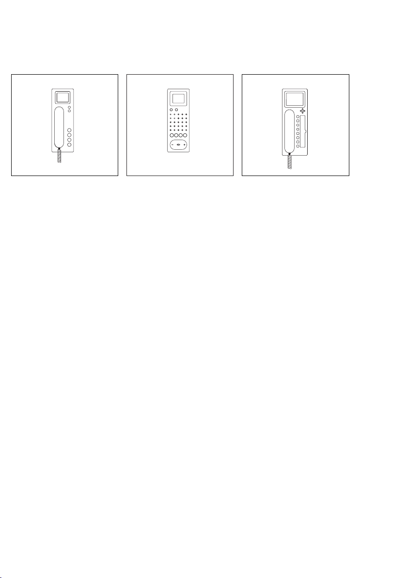
BTSV 850-...
Standard bus telephone with colour
monitor. Connection at bus cores
TaM and TbM.
• Calling, speech, vision, door
release and storey call
• Colour monitor 6.3 cm (2.5")
• Door release and light button
• Internal speech communication
• 10 ring tones
• Call and speech volume can be
modified in 5 stages
• Silencing button for the ring tone
• Double assignment of the light
button and silencing button
possible.
• Monitor button for current picture
• Brightness and colour regulation
• Potential-free contact for
additional signalling device
BFSV 850-0 W
Standard handsfree bus telephone
with colour monitor Connection to
bus cores TaM and TbM.
• Calling, handsfree/push-to-talk
speech, door release and storey calls
• Colour monitor 6.3 cm (2.5")
• Speech/control button
• Door release and light button
• Internal speech communication
• 10 ring tones
• Call and speech volume can be
modified in 5 stages
• Silencing button for the ring tone
• Double assignment of the light
button and silencing button
possible.
• Monitor button for current picture
• Brightness and colour regulation
• Potential-free contact for
additional signalling device
BTCV 850-...
Deluxe bus telephone with colour
monitor. Connection at bus cores
TaM and TbM.
• Calling, speech, vision, door
release and storey call
• Colour monitor 8.8 cm (3.5")
• Door release and light button
• Internal speech communication
• 11 ring tones including chime
• Call and speech volume can be
modified in 5 stages
• Silencing button for the ring tone
• 7 keys for switching and control
functions with double assignment
facility
• 7 LEDs under the buttons for
display of switching statuses
• Monitor button for current picture
• Potential-free contact for
additional signalling device
• Integrated video memory for 28
pictures, upgradable with SD card
• 5-way button for video memory
and zoom function
22
Page 23
4 In-Home: Video users
Accessories
BNS 750-...
Bus secondary signal unit, for
signalling door and storey door calls
in another room or corridor.
Connection to In-Home bus: Audio
Call volume steplessly adjustable up
to max. 86 dB(A). Call differentiation
for door calls and storey calls.
Connection to In-Home: Video only
via BAA 650-...
ZPS 850-0
Parallel switching accessory for
integration into deluxe bus
telephone BTC 850-... Circuit board
for connection of an additional
power supply. When programming
manually, required from the third
BTC 850-... , when programming by
PC from the fifth BTC 850-... .
Supply 20 V - 30 V DC from
NG 602-... or VNG 602-..., current
consumption max. 100 mA
ZAR 850-0
Interfacing relay accessory for
integration into bus telephones
BTS 850-... or BTC 850-... Universal
switching relay for secondary signal
unit, video interfacing or switching
relay.
Potential-free switching contact
max. 15 V AC, 30 V DC, 1 A,
switching time 0.4 secs. – 19 mins
Supply via the In-Home bus.
In their basic equipment
configuration, bus telephones
BTSV/BTCV 850-... provide one
potential-free contact.
ZARF 850-0
Handsfree interfacing relay accessory
for integration in the handsfree bus
telephone BFS 850-...
Universal switching relay for
secondary signal unit, video
actuation or switching relay,
potential-free switching contact.
Potential-free contact max.
15 V AC, 30 V DC, 1 A, switching
time 0.4 secs. – 19 mins. Supply via
the In-Home bus.
23
Page 24
4 In-Home: Video users
Accessories
ZTS 800-...
Standard table-top accessory for bus
telephones BTS 850-... and
BFS 850-... for conversion from a
wall to a table mounted unit.
Connection of the table top unit to
an 8-pin telecom socket type UAE 8.
ZTCV 850-...
Deluxe table-top accessory for the
bus telephone BTCV 850-...
Conversion from a wall to a table
unit. Connection of the table unit to
an 8-pin Telecom socket 8 (8)
junction box.
ZTC 800-...
Deluxe table-top accessory for the
bus telephone BTC 850-... for
conversion from a wall to a table top
unit. Connection of the table top
unit to an 8-pin telecom socket type
UAE 8.
ZTSV 850-...
Standard table-top accessory for
converting bus house telephone
BTSV/BFSV 850-... from a wall to a
table-top unit. Connection of the
table unit to an 8-pin Telecom
socket 8 (8) junction box.
24
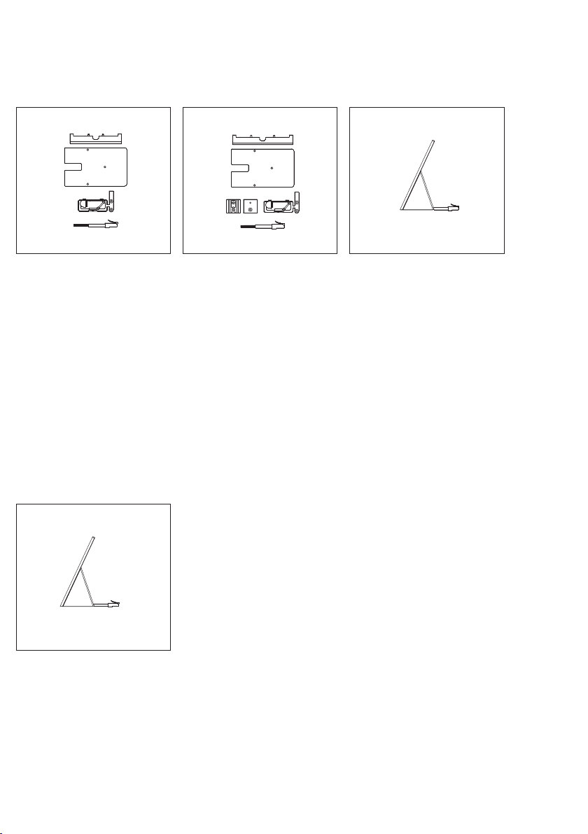
Page 25
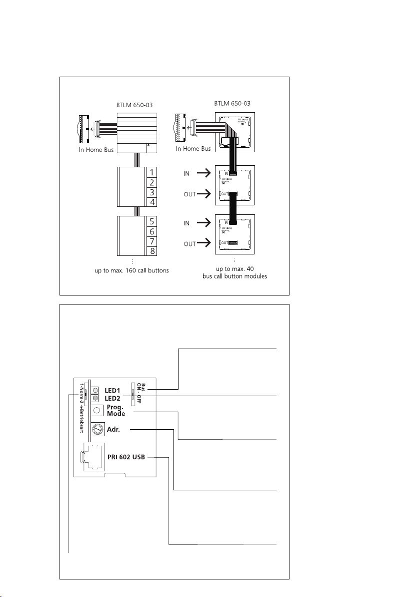
5 Installation
Bus call button module, bus video line rectifier
Bus On - OFF
In-Home bus: Video can be
switched on and off.
LED1, LED2
LED1 = Operational LED
LED2 = Error LED
Prog. mode
Button for programming mode
ON/OFF.
Addr.
Addresses from 1-15 (1-F) must
be set in multiple-line systems.
1 - Norm - 2
Operating mode switch:
1 = Reverse compatible
(with BVSG 650-...)
Norm = Operation as a new
system
2 = Increased range mode
PRI 602 USB
The socket for connection of
PRI 602-... USB is only available
if the ZBVG 650-... is plugged
in.
Bus call button module
Connection of the bus call button
modules to the bus door
loudspeaker via ribbon cable. The
name plate lighting is supplied from
the terminal block of the
BTLM 650-03.
The number of bus call button
modules which can be illuminated
depends on the overall load of the
TR 603-... (1300 mA).
Bus video line rectifier
At bus video line rectifier
BVNG 650-0, the
selector switch
Norm in a new system (as-delivered
status). If bus telephones from the
predecessor series are used within
the line, (e.g. BTS/BTC 750-02 with
bus video receiver BVE 650-...), the
operating mode switch must be set
to 1. A compatibility list is provided
in chapter 9, page 88.
The address is set at the bus video
line rectifier using the
rotary switch. In single line systems,
this is address 1 in the as-delivered
status. This setting does not need to
be altered. In multiple-line systems,
the bus video line rectifiers are
addressed in consecutive sequence.
operating mode
must be set to
“Addr.”
25
Page 26
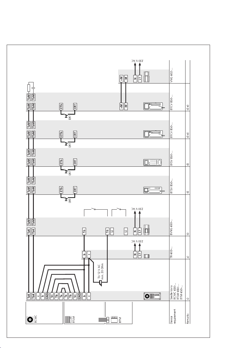
5 Installation
AS-TVHa-1/1 Siedle Vario
26
Page 27
AS-TVHa-1/1 Siedle Vario
Mode of operation
Calling, speech and video between
the door station and the connected
bus telephones BTSV/BFSV/
BTCV 850-... with colour monitor.
Audio and video privacy of existing
calls is assured. Door release button
for the door release function, light
button for the light switching
function. Pressing the monitor button
will show the camera picture from
the door station which placed the last
door call. This function is only
possible if no call exists.
Connection of a storey call button
(ERT) for calling from an apartment
door. Ring tones can be selected for
calls from the front door, apartment
door or internal calls. Connection of
other bus telephones with colour
monitor when looping through from
one device to the next. Other bus
door loudspeakers with video are
connected with bus video distributors
BVVU 650-... or BVVS 650-...
Supplementary functions
• Internal speech communication
possible between bus telephones
BTSV/BFSV/BTCV 850-0.
Connection of bus telephones
•
BTS/BFS/BTC 850-... or devices for
switching and control functions via
bus audio decoupler BAA 650-...
For more information, see chapter 6,
page 46-47.
Switching and control functions
•
possible with bus switching modules
BSM 650-..., BSE 650-... and
BEM 650-... , feedback to bus
telephones BTC/BTCV 850-...
programmable via LED. For more
information, see chapter 8,
page 77-79.
Bus secondary signal unit
•
BNS 750-... possible, chapter 8,
page 84.
Parallel door and storey call
•
Up to 8 bus telephones with colour
monitor can be called simultaneously
via one call button. From the second
bus telephone, each bus telephone
must be additionally supplied at the
terminals +M/-M.
Selective dialling of the door
•
possible via additional free
station
buttons.
Video memory function possible
•
with the bus telephone
BTCV 850-..., additional installation
required.
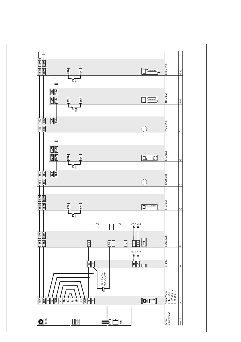
Remarks
The TR 603-... (12 V AC, 1.3 A)
a)
can supply 1 door release button
and max. 24 bus call button
modules with LED lighting
(BTM 650-01, -02, -03 and -04).
With more than 24 illuminated bus
call button modules, an additional
TR 603-... is required.
Current consumers in the AS
diagram:
Door release appr. 600 mA
Camera heating 100 mA
LED lighting per bus call button
module 25 mA
b) Door release contact load in the
bus video line rectifier BVNG 650-...
max. 15 V AC, 30 V DC, 2 A.
• Light contact load in the bus video
line rectifier max. 15 V AC, 30 V DC,
2 A.
c) Door release 12 V AC, use at least
20 Ohm, (e.g. TÖ 615-...), for
possible connection variants see
chapter 8, page 80.
d) Conductor length bus telephone storey call button ERT max. 50 m.
e) When using the internal video
memory module, the bus telephone
BTCV 850-... must be supplied by an
additional direct voltage
(20 - 30 V DC, 350 mA).
NG 602-... or VNG 602-... can be
used for this purpose. Connection of
the supply at terminals +M/-M. For
more information, see chapter 8,
page 82.
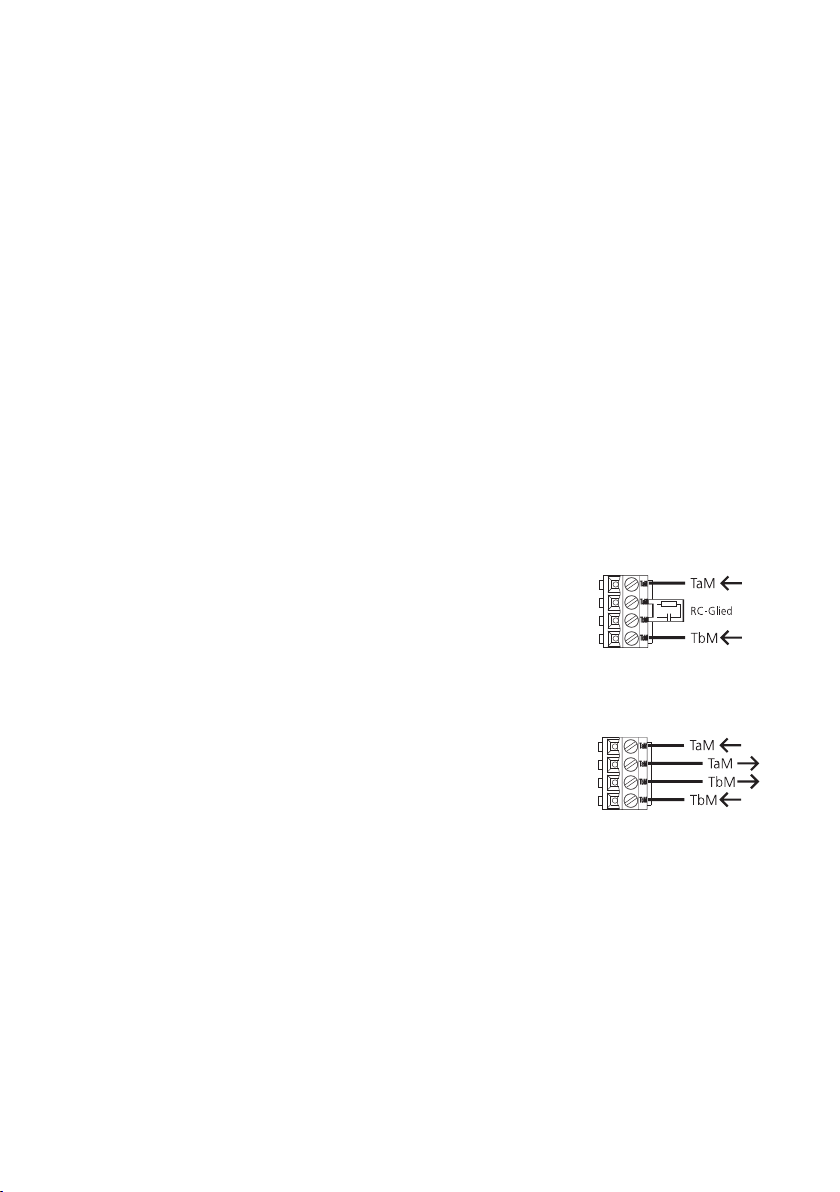
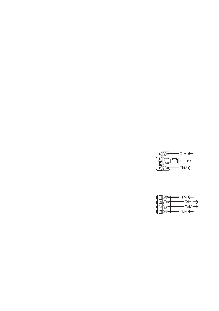
Installation
In each bus telephone with colour
monitor, there is a terminating
circuit board connected in the asdelivered status in the centre of the
connecting terminals TaM and TbM.
This circuit board is an RC element
which comprises a resistor with
100 Ohm and a capacitor 1 nF.
When looping through from one bus
telephone to the next in the
installation, this terminating circuit
board must be removed. If,
however, bus distributors are used in
the installation, or if there is only 1
bus telephone with colour monitor
in the line, the terminating element
remains in the bus telephone.
Terminal
BTSV/BFSV/BTCV 850-0
Connection for one bus telephone
or the last bus telephone in the line.
Connection when looping
through from one bus telephone to
another.
Cable laying
Only signals from the In-Home
!!
bus may be transmitted via the laid
conductor material. No additional
transmission is possible, for instance
to PBX extensions of a telephone
system or an S0 bus (ISDN). The
camera branch and monitor branch
must be laid in a separate cable and
must not be installed inside the
same conduit. This can result in
disturbance to the picture
composition.
27
Page 28
5 Installation
AS-TVHa-1/1 Siedle Vario with BVVU 650-...
Loop-through connection
For notes on the wiring diagram, see the previous page
28
Page 29

5 Installation
AS-TVHa-1/1 Siedle Vario with BVVU 650-...
Star-shaped installation
For notes on the wiring diagram, see the previous page
29
Page 30

5 Installation
AS-TVHa-1/1 Siedle custom-fit door loudspeaker
30
Page 31

AS-TVHa-1/1 Siedle custom-fit
door loudspeaker
Mode of operation
Calling, speech and video between
the door station and the connected
bus telephones BTSV/BFSV/
BTCV 850-... with colour monitor.
Audio and video privacy of existing
calls is assured. Door release button
for the door release function, light
button for the light switching
function. By pressing the monitor
button, the camera picture of the
external camera is displayed. This
function is only possible if no call
exists.
Connection of a storey call button
(ERT) for calling from an apartment
door. Ring tones can be selected for
calls from the front door, apartment
door or internal calls.
Connection of other bus telephones
with colour monitor when looping
through from one device to the
next. Other bus door loudspeakers
with video are connected with bus
video distributors BVVU 650-... or
BVVS 650-... .
Supplementary functions
• Internal speech communication
possible between bus telephones
BTSV/BFSV/BTCV 850-0.
Connection of bus telephones
•
BTS/BFS/BTC 850-... or devices for
switching and control functions via
bus audio decoupler BAA 650-...
For more information, see chapter 6,
page 46-47.
Switching and control functions
•
possible with bus switching modules
BSM 650-..., BSE 650-... and
BEM 650-... , feedback to bus
telephones BTC/BTCV 850-...
programmable via LED. For more
information, see chapter 8,
page 77-79.
Bus secondary signal unit
•
BNS 750-... possible, chapter 8,
page 84.
Parallel door and storey call
•
Up to 8 bus telephones with colour
monitor can be called simultaneously
via one call button. From the second
bus telephone, each bus telephone
must be additionally supplied at the
terminals +M/-M.
Selective dialling of the door
•
possible via additional free
station
buttons.
Video memory function possible
•
with the bus telephone
BTCV 850-..., additional installation
required.
Remarks
The NG 602-... (12 V AC, 1.6 A)
a)
can also provide a supply for
illumination of existing call buttons.
A voltage of 12 V AC max. 1000 mA
is available for illumination. With a
higher current consumption, an
additional transformer must be used.
Current consumers in the AS
diagram:
Door release appr. 600 mA
Illumination of existing call buttons
b) Door release contact load in the
bus video line rectifier BVNG 650-...
max. 15 V AC, 30 V DC, 2 A.
• Light contact load in the bus video
line rectifier max. 15 V AC, 30 V DC,
2 A.
c) Door release 12 V AC, use at least
20 Ohm, (e.g. TÖ 615-...), for
possible connection variants see
chapter 8, page 80.
d) Conductor length bus telephone storey call button ERT max. 50 m.
e) When using the internal video
memory module, the bus telephone
BTCV 850-... must be supplied by an
additional direct voltage
(20 - 30 V DC, 350 mA).
NG 602-... or VNG 602-... can be
used for this purpose. Connection of
the supply at terminals +M/-M. For
more information, see chapter 8,
page 82.
f) The camera CEC 612-... can also
be supplied via BVS 650-... when
used indoors.
Installation
In each bus telephone with colour
monitor, there is a terminating
circuit board connected in the asdelivered status in the centre of the
connecting terminals TaM and TbM.
This circuit board is an RC element
which comprises a resistor with
100 Ohm and a capacitor 1 nF.
When looping through from one bus
telephone to the next in the
installation, this terminating circuit
board must be removed. If,
however, bus distributors are used in
the installation, or if there is only 1
bus telephone with colour monitor
in the line, the terminating element
remains in the bus telephone.
Terminal
BTSV/BFSV/BTCV 850-0
Connection for one bus telephone
or the last bus telephone in the line.
Connection when looping
through from one bus telephone to
another.
Cable laying
Only signals from the In-Home
!!
bus may be transmitted via the laid
conductor material. No additional
transmission is possible, for instance
to PBX extensions of a telephone
system or an S0 bus (ISDN). The
camera branch and monitor branch
must be laid in a separate cable and
must not be installed inside the
same conduit. This can result in
disturbance to the picture
composition.
31
Page 32

5 Installation
AS-TVHa-1/1 Siedle Classic
32
Page 33
AS-TVHa-1/1 Siedle Classic
Mode of operation
Calling, speech and video between
the door station and the connected
bus telephones BTSV/BFSV/
BTCV 850-... with colour monitor.
Audio and video privacy of existing
calls is assured. Door release button
for the door release function, light
button for the light switching
function. Pressing the monitor button
will show the camera picture from
the door station which placed the last
door call. This function is only
possible if no call exists.
Connection of a storey call button
(ERT) for calling from an apartment
door. Ring tones can be selected for
calls from the front door, apartment
door or internal calls.Connection of
other bus telephones with colour
monitor when looping through from
one device to the next. Other bus
door loudspeakers with video are
connected with bus video distributors
BVVU 650-... or BVVS 650-...
Supplementary functions
• Internal speech communication
possible between bus telephones
BTSV/BTCV 850-0.
Connection of bus telephones
•
BTS/BFS/BTC 850-... or devices for
switching and control functions via
bus audio decoupler BAA 650-...
For more information, see chapter 6,
page 46-47.
Switching and control functions
•
possible with bus switching modules
BSM 650-..., BSE 650-... and
BEM 650-... , feedback to bus
telephones BTC/BTCV 850-...
programmable via LED. For more
information, see chapter 8,
page 77-79.
Bus secondary signal unit
•
BNS 750-... possible, chapter 8,
page 84.
Parallel door and storey call
•
Up to 8 bus telephones with colour
monitor can be called simultaneously
via one call button. From the second
bus telephone, each bus telephone
must be additionally supplied at the
terminals +M/-M.
Selective dialling of the door
•
possible via additional free
station
buttons.
Video memory function possible
•
with the bus telephone
BTCV 850-..., additional installation
required.
Remarks
The TR 603-... (12 V AC, 1.3 A)
a)
can supply 1 door release and the
LED lighting of max. 30 call buttons.
With more than 30 illuminated bus
call button modules, an additional
TR 603-... is required.
Current consumers in the AS
diagram:
Door release appr. 600 mA
Camera heating 100 mA
LED lighting of call buttons, 20 mA
per button
b) Door release contact load in the
bus video line rectifier BVNG 650-...
max. 15 V AC, 30 V DC, 2 A.
• Light contact load in the bus video
line rectifier max. 15 V AC, 30 V DC,
2 A.
c) Door release 12 V AC, use at least
20 Ohm, (e.g. TÖ 615-...), for
possible connection variants see
chapter 8, page 80.
• Current consumption LED lighting
of call buttons 20 mA at terminal
b/c.
d) Conductor length bus telephone storey call button ERT max. 50 m.
e) When using the internal video
memory module, the bus telephone
BTCV 850-... must be supplied by an
additional direct voltage
(20 - 30 V DC, 350 mA).
NG 602-... or VNG 602-... can be
used for this purpose. Connection of
the supply at terminals +M/-M. For
more information, see chapter 8,
page 82.
Installation
In each bus telephone with colour
monitor, there is a terminating
circuit board connected in the asdelivered status in the centre of the
connecting terminals TaM and TbM.
This circuit board is an RC element
which comprises a resistor with
100 Ohm and a capacitor 1 nF.
When looping through from one bus
telephone to the next in the
installation, this terminating circuit
board must be removed. If,
however, bus distributors are used in
the installation, or if there is only 1
bus telephone with colour monitor
in the line, the terminating element
remains in the bus telephone.
Terminal
BTSV/BFSV/BTCV 850-0
Connection for one bus telephone
or the last bus telephone in the line.
Connection when looping
through from one bus telephone to
another.
Cable laying
Only signals from the In-Home
!!
bus may be transmitted via the laid
conductor material. No additional
transmission is possible, for instance
to PBX extensions of a telephone
system or an S0 bus (ISDN). The
camera branch and monitor branch
must be laid in a separate cable and
must not be installed inside the
same conduit. This can result in
disturbance to the picture
composition.
33
Page 34

5 Installation
AS-TVHa-1/1 Siedle Steel
34
Page 35

AS-TVHa-1/1 Siedle Steel
Mode of operation
Calling, speech and video between
the door station and the connected
bus telephones BTSV/BFSV/
BTCV 850-... with colour monitor.
Audio and video privacy of existing
calls is assured. Door release button
for the door release function, light
button for the light switching
function. Pressing the monitor button
will show the camera picture from
the door station which placed the last
door call. This function is only
possible if no call exists.
Connection of a storey call button
(ERT) for calling from an apartment
door. Ring tones can be selected for
calls from the front door, apartment
door or internal calls.Connection of
other bus telephones with colour
monitor when looping through from
one device to the next. Other bus
door loudspeakers with video are
connected with bus video distributors
BVVU 650-... or BVVS 650-... .
Supplementary functions
• Internal speech communication
possible between bus telephones
BTSV/BFSV/BTCV 850-0.
Connection of bus telephones
•
BTS/BFS/BTC 850-... or devices for
switching and control functions via
bus audio decoupler BAA 650-...
For more information, see chapter 6,
page 46-47.
Switching and control functions
•
possible with bus switching modules
BSM 650-..., BSE 650-... and
BEM 650-... , feedback to bus
telephones BTC/BTCV 850-...
programmable via LED. For more
information, see chapter 8,
page 77-79.
Bus secondary signal unit
•
BNS 750-... possible, chapter 8,
page 84.
Parallel door and storey call
•
Up to 8 bus telephones with colour
monitor can be called simultaneously
via one call button. From the second
bus telephone, each bus telephone
must be additionally supplied at the
terminals +M/-M.
Selective dialling of the door
•
possible via additional free
station
buttons.
Video memory function possible
•
with the bus telephone
BTCV 850-..., additional installation
required.
Remarks
The TR 603-... (12 V AC, 1.3 A)
a)
can supply 1 door release and the
LED lighting of max. 30 call buttons.
With more than 30 illuminated bus
call button modules, an additional
TR 603-... is required.
Current consumers in the AS
diagram:
Door release appr. 600 mA
Camera heating 100 mA
LED lighting of call buttons, 20 mA
per call button
b) Door release contact load in the
bus video line rectifier BVNG 650-...
max. 15 V AC, 30 V DC, 2 A.
• Light contact load in the bus video
line rectifier max. 15 V AC, 30 V DC,
2 A.
c) Door release 12 V AC, use at least
20 Ohm, (e.g. TÖ 615-...), for
possible connection variants see
chapter 8, page 80.
• Current consumption LED lighting
of call buttons 20 mA at terminal
b/c.
d) Conductor length bus telephone storey call button ERT max. 50 m.
e) When using the internal video
memory module, the bus telephone
BTCV 850-... must be supplied by an
additional direct voltage
(20 - 30 V DC, 350 mA).
NG 602-... or VNG 602-... can be
used for this purpose. Connection of
the supply at terminals +M/-M. For
more information, see chapter 8,
page 82.
Installation
In each bus telephone with colour
monitor, there is a terminating
circuit board connected in the asdelivered status in the centre of the
connecting terminals TaM and TbM.
This circuit board is an RC element
which comprises a resistor with
100 Ohm and a capacitor 1 nF.
When looping through from one bus
telephone to the next in the
installation, this terminating circuit
board must be removed. If,
however, bus distributors are used in
the installation, or if there is only 1
bus telephone with colour monitor
in the line, the terminating element
remains in the bus telephone.
Terminal
BTSV/BFSV/BTCV 850-0
Connection for one bus telephone
or the last bus telephone in the line.
Connection when looping
through from one bus telephone to
another.
Cable laying
Only signals from the In-Home
!!
bus may be transmitted via the laid
conductor material. No additional
transmission is possible, for instance
to PBX extensions of a telephone
system or an S0 bus (ISDN). The
camera branch and monitor branch
must be laid in a separate cable and
must not be installed inside the
same conduit. This can result in
disturbance to the picture
composition.
35
Page 36

5 Installation
AS-TVHa-1/2 Siedle Vario
36
Page 37

AS-TVHa-1/2 Siedle Vario
2 door stations
Mode of operation
Calling, speech and video between
the door station and the connected
bus telephones BTSV/BFSV/
BTCV 850-... with colour monitor.
Audio and video privacy of existing
calls is assured. The door release
button for the door release function
from the door station at which the
last call was placed, light button for
the light switching function. Pressing
the monitor button will show the
camera picture from the door station
which placed the last door call. This
function is only possible if no call
exists.
Connection of a storey call button
(ERT) for calling from an apartment
door. Ring tones can be selected for
calls from the front door, apartment
door or internal calls.
Connection of other bus telephones
with colour monitor when looping
through from one device to the
next. Other bus door loudspeakers
with video are connected with bus
video distributors BVVU 650-... or
BVVS 650-... .
Supplementary functions
• Internal speech communication
possible between bus telephones
BTSV/BFSV/BTCV 850-0.
Connection of bus telephones
•
BTS/BFS/BTC 850-... or devices for
switching and control functions via
bus audio decoupler BAA 650-...
For more information, see chapter 6,
page 46-47.
Switching and control functions
•
possible with bus switching modules
BSM 650-..., BSE 650-... and
BEM 650-... , feedback to bus
telephones BTC/BTCV 850-...
programmable via LED. For more
information, see chapter 8,
page 77-79.
Bus secondary signal unit
•
BNS 750-... possible, chapter 8,
page 84.
Parallel door and storey call
•
Up to 8 bus telephones with colour
monitor can be called simultaneously
via one call button. From the second
bus telephone, each bus telephone
must be additionally supplied at the
terminals +M/-M.
Selective dialling of the door
•
possible via additional free
station
buttons.
Video memory function possible
•
with the bus telephone
BTCV 850-..., additional installation
required.
Remarks
The TR 603-... (12 V AC, 1.3 A)
a)
can supply 1 door release button
and max. 20 bus call button
modules with LED lighting
(BTM 650-01, -02, -03 and -04).
With more than 20 illuminated bus
call button modules, or additional
door stations, an additional
TR 603-... is required.
Current consumers in the AS
diagram:
Door release appr. 600 mA
Camera heating 100 mA
LED lighting per bus call button
module 25 mA
b) Door release contact load in the
bus video line rectifier BVNG 650-...
max. 15 V AC, 30 V DC, 2 A.
• Light contact load in the bus video
line rectifier max. 15 V AC, 30 V DC,
2 A.
c) Door release 12 V AC, use at least
20 Ohm, (e.g. TÖ 615-...), for
possible connection variants see
chapter 8, page 80.
• Current consumption bus call
button module 25 mA at terminal
b/c.
d) Conductor length bus telephone storey call button ERT max. 50 m.
e) When using the internal video
memory module, the bus telephone
BTCV 850-... must be supplied by an
additional direct voltage
(20 - 30 V DC, 350 mA).
NG 602-... or VNG 602-... can be
used for this purpose. Connection of
the supply at terminals +M/-M. For
more information, see chapter 8,
page 82.
Installation
In each bus telephone with colour
monitor, there is a terminating
circuit board connected in the asdelivered status in the centre of the
connecting terminals TaM and TbM.
This circuit board is an RC element
which comprises a resistor with
100 Ohm and a capacitor 1 nF.
When looping through from one bus
telephone to the next in the
installation, this terminating circuit
board must be removed. If,
however, bus distributors are used in
the installation, or if there is only 1
bus telephone with colour monitor
in the line, the terminating element
remains in the bus telephone.
Terminal
BTSV/BFSV/BTCV 850-0
Connection for one bus telephone
or the last bus telephone in the line.
Connection when looping
through from one bus telephone to
another.
Cable laying
Only signals from the In-Home
!!
bus may be transmitted via the laid
conductor material. No additional
transmission is possible, for instance
to PBX extensions of a telephone
system or an S0 bus (ISDN). The
camera branch and monitor branch
must be laid in a separate cable and
must not be installed inside the
same conduit. This can result in
disturbance to the picture
composition.
37
Page 38

5 Installation
AS-TVHa-2/1 multiple line system
38
Page 39

AS-TVHa-2/1 multiple line system
Mode of operation
Calling, speech and video between
the door station and the connected
bus telephones BTSV/BFSV/
BTCV 850-... with colour monitor.
Audio and video privacy of existing
calls is assured. Door release button
for the door release function, light
button for the light switching
function. Pressing the monitor
button will show the camera picture
from the door station which placed
the last door call. This function is
only possible if no call exists.
Connection of a storey call button
(ERT) for calling from an apartment
door. Ring tones can be selected for
calls from the front door, apartment
door or internal calls.
Connection of other bus telephones
with colour monitor when looping
through from one device to the
next. Other bus door loudspeakers
with video are connected with bus
video distributors BVVU 650-... or
BVVS 650-... .
In a multiple line system comprising
only 2 lines, connection between the
two bus video line rectifiers is
possible without bus distributor
BVVU 650-... . Up to 15 lines can be
linked via BVVU 650-... .
Supplementary functions
• Internal speech communication
between the bus telephones
BTSV/BFSV/BTCV 850-... only within
the same line.
Connection of bus telephones
•
BTS/BFS/BTC 850-... or devices for
switching and control functions via
bus audio decoupler BAA 650-...
For more information, see chapter 6,
page 46-47.
Switching and control functions
•
possible with bus switching modules
BSM 650-..., BSE 650-... and
BEM 650-... , feedback to bus
telephones BTC/BTCV 850-...
programmable via LED. Switching
and control functions are possible
across different lines. For more
information, see chapter 8,
page 77-79.
Bus secondary signal unit
•
BNS 750-... possible, chapter 8,
page 84.
Parallel door and storey call
•
Up to 8 bus telephones with colour
monitor can be called simultaneously
via one call button. From the second
bus telephone, each bus telephone
must be additionally supplied at the
terminals +M/-M.
Selective dialling of the door
•
possible via additional free
station
buttons.
Video memory function possible
•
with the bus telephone
BTCV 850-..., additional installation
required.
Remarks
The TR 603-... (12 V AC, 1.3 A)
a)
can supply 1 door release button
and max. 24 bus call button
modules with LED lighting
(BTM 650-01, -02, -03 and -04).
With more than 24 illuminated bus
call button modules, an additional
TR 603-... is required.
Current consumers in the AS
diagram:
Door release appr. 600 mA
Camera heating 100 mA
LED lighting per bus call button
module 25 mA
b) Door release contact load in the
bus video line rectifier BVNG 650-...
max. 15 V AC, 30 V DC, 2 A.
• Light contact load in the bus video
line rectifier max. 15 V AC, 30 V DC,
2 A.
c) Door release 12 V AC, use at least
20 Ohm, (e.g. TÖ 615-...), for
possible connection variants see
chapter 8, page 80.
• Current consumption bus call
button module 25 mA at terminal
b/c.
d) Conductor length bus telephone storey call button ERT max. 50 m.
e) When using the internal video
memory module, the bus telephone
BTCV 850-... must be supplied by an
additional direct voltage
(20 - 30 V DC, 350 mA).
NG 602-... or VNG 602-... can be
used for this purpose. Connection of
the supply at terminals +M/-M. For
more information, see chapter 8,
page 82.
Installation
In each bus telephone with colour
monitor, there is a terminating
circuit board connected in the asdelivered status in the centre of the
connecting terminals TaM and TbM.
This circuit board is an RC element
which comprises a resistor with
100 Ohm and a capacitor 1 nF.
When looping through from one bus
telephone to the next in the
installation, this terminating circuit
board must be removed. If,
however, bus distributors are used in
the installation, or if there is only 1
bus telephone with colour monitor
in the line, the terminating element
remains in the bus telephone.
Terminal
BTSV/BFSV/BTCV 850-0
Connection for one bus telephone
or the last bus telephone in the line.
Connection when looping
through from one bus telephone to
another.
Cable laying
Only signals from the In-Home
!!
bus may be transmitted via the laid
conductor material. No additional
transmission is possible, for instance
to PBX extensions of a telephone
system or an S0 bus (ISDN). The
camera branch and monitor branch
must be laid in a separate cable and
must not be installed inside the
same conduit. This can result in
disturbance to the picture
composition.
39
Page 40

5 Installation
AS-TVHa-1/1 call via display call module DRM 611-0
40
Page 41

AS-TVHa-1/1 call via display call
module DRM 611-0
Mode of operation
Calling, speech and video between
the door station and the connected
bus telephones BTSV/BFSV/
BTCV 850-... with colour monitor.
Dialling of bus telephones via the
display call module. Selection of
names takes place in alphabetical
order. Connection of bus call button
modules possible, e.g. for door call
at the reception.
Audio and video privacy of existing
calls is assured. Door release button
for the door release function, light
button for the light switching
function. Pressing the monitor
button will show the camera picture
from the door station which placed
the last door call. This function is
only possible if no call exists.
Connection of a storey call button
(ERT) for calling from an apartment
door. Ring tones can be selected for
calls from the front door, apartment
door or internal calls.
Connection of other bus telephones
with colour monitor when looping
through from one device to the
next. Other bus door loudspeakers
with video are connected with bus
video distributors BVVU 650-... or
BVVS 650-... .
Supplementary functions
• Internal speech communication
possible between bus telephones
BTSV/BFSV/BTCV 850-0.
Connection of bus telephones
•
BTS/BFS/BTC 850-... or devices for
switching and control functions
via bus audio decoupler BAA 650-...
For more information see
page 46-47.
Switching and control functions
•
possible with bus switching modules
BSM 650-..., BSE 650-... and
BEM 650-... , feedback to bus
telephones BTC/BTCV 850-...
programmable via LED. For more
information, see chapter 8,
page 77-79.
Bus secondary signal unit
•
BNS 750-... possible, page 84.
Parallel door and storey call
•
Up to 8 bus telephones with colour
monitor can be called simultaneously
via one call button. From the second
bus telephone, each bus telephone
must be additionally supplied at the
terminals +M/-M.
Selective dialling of the door
•
possible via additional free
station
buttons.
Video memory function possible
•
with the bus telephone
BTCV 850-..., additional installation
required.
Remarks
The TR 603-... (12 V AC, 1.3 A)
a)
can supply 1 door release button
and max. 24 bus call button
modules with LED lighting
(BTM 650-01, -02, -03 and -04).
With more than 24 illuminated bus
call button modules, an additional
TR 603-... is required.
Current consumers in the AS
diagram:
Door release appr. 600 mA
Camera heating 100 mA
LED lighting per bus call button
module 25 mA
b) Door release contact load in the
bus video line rectifier BVNG 650-...
max. 15 V AC, 30 V DC, 2 A.
• Light contact load in the bus video
line rectifier max. 15 V AC, 30 V DC,
2 A.
c) Door release 12 V AC, use at least
20 Ohm, (e.g. TÖ 615-...), for
possible connection variants see
page 80.
• Current consumption bus call
button module 25 mA at terminal
b/c.
d) Conductor length bus telephone storey call button ERT max. 50 m.
e) When using the internal video
memory module, the bus telephone
BTCV 850-... must be supplied by an
additional direct voltage
(20 - 30 V DC, 350 mA).
NG 602-... or VNG 602-... can be
used for this purpose. Connection of
the supply at terminals +M/-M. For
more information, see chapter 8,
page 82.
h) For programming names, the
programming software
PRS 602-0 and programming
interface PRI 602-0/BIM 650-... are
required. Names are entered in the
display call module using the
PRS 602-0 from V 1.3.1 Connection
with e.g. ZWA 640-...
Installation
In each bus telephone with colour
monitor, there is a terminating
circuit board connected in the asdelivered status in the centre of the
connecting terminals TaM and TbM.
When looping through from one bus
telephone to the next in the
installation, this terminating circuit
board must be removed. If,
however, bus distributors are used in
the installation, or if there is only 1
bus telephone with colour monitor
in the line, the terminating element
remains in the bus telephone.
Terminal
BTSV/BFSV/BTCV 850-0
Connection for one bus telephone
or the last bus telephone in the line.
Connection when looping
through from one bus telephone to
another.
Cable laying
Only signals from the In-Home
!!
bus may be transmitted via the laid
conductor material. No additional
transmission is possible, for instance
to PBX extensions of a telephone
system or an S0 bus (ISDN). The
camera branch and monitor branch
must be laid in a separate cable and
must not be installed inside the
same conduit. This can result in
disturbance to the picture
composition.
41
Page 42

5 Installation
AS-TVHa-1/1 DoorCom Analog DCA 650-...
42
Page 43

AS-TVHa-1/1 DoorCom Analog
DCA 650-...
Mode of operation
Calling and speech between the door
station and the connected a/b
telephones of a telephone system.
The DoorCom-Analog DCA 650-02 is
able to forward the call from up to
31 bell buttons to a telephone
system. The DCA 650-02 calls the
PBX extensions of the telephone
system using dual-tone multiple
frequency dialling DTMF. Audio and
video privacy of existing calls from
other telephones is assured. The
function for door release and light
switching via DTMF symbols is
possible at connected a/b telephones
in the telephone system.Connection
of other bus telephones with colour
monitor when looping through from
one device to the next. Other bus
door loudspeakers with video are
connected with bus video distributors
BVVU 650-... or BVVS 650-...
Supplementary functions
• Internal speech communication
possible between bus telephones
BTSV/BFSV/BTCV 850-0.
Connection of bus telephones
•
BTS/BFS/BTC 850-... or devices for
switching and control functions via
bus audio decoupler BAA 650-...
For more information, see chapter 6,
page 46-47.
Switching and control functions
•
possible with the bus switching
modules BSM 650-..., BSE 650-...
and BEM 650-... are possible.
Acknowledgement can be
programmed at bus telephones
BTC/BTCV 850-... via LED. For more
information, see chapter 8,
page 77-79.
Bus secondary signal unit
•
BNS 750-... possible, chapter 8,
page 84.
Parallel door and storey call
•
Up to 8 bus telephones with colour
monitor can be called simultaneously
via one call button. From the second
bus telephone, each bus telephone
must be additionally supplied at the
terminals +M/-M.
Selective dialling of the door
•
possible via additional free
station
buttons.
Video memory function possible
•
with the bus telephone
BTCV 850-..., additional installation
required.
Remarks
The TR 603-... (12 V AC, 1.3 A)
a)
can supply 1 door release button and
max. 16 bus call button modules
with LED lighting (BTM 650-01, -02,
-03 and -04). With more than 16
illuminated bus call button modules,
an additional TR 603-... is required.
Current consumers in the AS
diagram: Door release appr. 600 mA
Camera heating 100 mA
DoorCom Analog 100 mA
with DCSF 600-... 200 mA
LED lighting per bus call button
module 25 mA
b) Door release contact load in the
bus video line rectifier BVNG 650-...
max. 15 V AC, 30 V DC, 2 A.
• Light contact load in the bus video
line rectifier max. 15 V AC, 30 V DC,
2 A.
c) Door release 12 V AC, use at least
20 Ohm, (e.g. TÖ 615-...), for
possible connection variants see
chapter 8, page 80.
• Current consumption bus call
button module 25 mA at terminal
b/c.
d) Conductor length bus telephone storey call button ERT max. 50 m.
e) When using the internal video
memory module, the bus telephone
BTCV 850-... must be supplied by an
additional direct voltage
(20 - 30 V DC, 350 mA).
NG 602-... or VNG 602-... can be
used for this purpose. Connection of
the supply at terminals +M/-M. For
more information, see chapter 8,
page 82.
f) If the predecessor model
DCA 650-0 is used, the operating
mode switch of the BNG 650-0 must
be in position 1.
g) The maximum distance of the
DCA 650-... from the TR 603-... is
20 m. With greater distances, an
additional transformer is required for
the DCA 650-... . If several
DCA 650-... units are used within a
system, each DCA 650-... must be
supplied by its own transformer.
Installation
In each bus telephone with colour
monitor, there is a terminating
circuit board connected in the asdelivered status in the centre of the
connecting terminals TaM and TbM.
This circuit board is an RC element
which comprises a resistor with
100 Ohm and a capacitor 1 nF.
When looping through from one bus
telephone to the next in the
installation, this terminating circuit
board must be removed. If,
however, bus distributors are used in
the installation, or if there is only 1
bus telephone with colour monitor
in the line, the terminating element
remains in the bus telephone.
Terminal
BTSV/BFSV/BTCV 850-0
Connection for one bus telephone
or the last bus telephone in the line.
Connection when looping
through from one bus telephone to
another.
Cable laying
Only signals from the In-Home
!!
bus may be transmitted via the laid
conductor material. No additional
transmission is possible, for instance
to PBX extensions of a telephone
system or an S0 bus (ISDN). The
camera branch and monitor branch
must be laid in a separate cable and
must not be installed inside the
same conduit. This can result in
disturbance to the picture
composition.
43
Page 44

5 Installation
AS-TVHa-1/1 additional external camera
44
Page 45

AS-TVHa-1/1 additional external
camera
Mode of operation
Calling, speech and video between
the door station and the connected
bus telephones BTSV/BFSV/
BTCV 850-... with colour monitor.
Audio and video privacy of existing
calls is assured. Door release button
for the door release function, light
button for the light switching
function. By pressing the monitor
button, the picture from the camera
with which the last connection
existed is displayed. This function is
only possible if no call exists. Dialling
the external camera can be
programmed to one of the buttons
on the bus telephone.
Connection of a storey call button
(ERT) for calling from an apartment
door. Ring tones can be selected for
calls from the front door, apartment
door or internal calls.
Connection of other bus telephones
with colour monitor when looping
through from one device to the
next. Other bus door loudspeakers
with video are connected with bus
video distributors BVVU 650-... or
BVVS 650-... .
Supplementary functions
• Internal speech communication
possible between bus telephones
BTSV/BFSV/BTCV 850-0.
Connection of bus telephones
•
BTS/BFS/BTC 850-... or devices for
switching and control functions via
bus audio decoupler BAA 650-...
For more information, see chapter 6,
page 46-47.
Switching and control functions
•
possible with bus switching modules
BSM 650-..., BSE 650-... and
BEM 650-... , feedback to bus
telephones BTC/BTCV 850-...
programmable via LED. For more
information, see chapter 8,
page 77-79.
Bus secondary signal unit
•
BNS 750-... possible, chapter 8,
page 84.
Parallel door and storey call
•
Up to 8 bus telephones with colour
monitor can be called simultaneously
via one call button. From the second
bus telephone, each bus telephone
must be additionally supplied at the
terminals +M/-M.
Selective dialling of the door
•
possible via additional free
station
buttons.
Video memory function possible
•
with the bus telephone
BTCV 850-..., additional installation
required.
Remarks
The TR 603-... (12 V AC, 1.3 A)
a)
can supply 1 door release button
and max. 24 bus call button
modules with LED lighting
(BTM 650-01, -02, -03 and -04).
With more than 24 illuminated bus
call button modules, an additional
TR 603-... is required.
Current consumers in the AS
diagram:
Door release appr. 600 mA
Camera heating 100 mA
LED lighting per bus call button
module 25 mA
b) Door release contact load in the
bus video line rectifier BVNG 650-...
max. 15 V AC, 30 V DC, 2 A.
• Light contact load in the bus video
line rectifier max. 15 V AC, 30 V DC,
2 A.
c) Door release 12 V AC, use at least
20 Ohm, (e.g. TÖ 615-...), for
possible connection variants see
chapter 8, page 80.
• Current consumption bus call
button module 25 mA at terminal
b/c.
d) Conductor length bus telephone storey call button ERT max. 50 m.
e) When using the internal video
memory module, the bus telephone
BTCV 850-... must be supplied by an
additional direct voltage
(20 - 30 V DC, 350 mA).
NG 602-... or VNG 602-... can be
used for this purpose. Connection of
the supply at terminals +M/-M. For
more information, see chapter 8,
page 82.
h) Activation of the BVA 650-... via
the programming button in the
BVA 650-... Further programming
corresponds to the procedure used
for programming a door call.
Installation
In each bus telephone with colour
monitor, there is a terminating
circuit board connected in the asdelivered status in the centre of the
connecting terminals TaM and TbM.
This circuit board is an RC element
which comprises a resistor with
100 Ohm and a capacitor 1 nF.
When looping through from one bus
telephone to the next in the
installation, this terminating circuit
board must be removed. If,
however, bus distributors are used in
the installation, or if there is only 1
bus telephone with colour monitor
in the line, the terminating element
remains in the bus telephone.
Terminal
BTSV/BFSV/BTCV 850-0
Connection for one bus telephone
or the last bus telephone in the line.
Connection when looping
through from one bus telephone to
another.
Cable laying
Only signals from the In-Home
!!
bus may be transmitted via the laid
conductor material. No additional
transmission is possible, for instance
to PBX extensions of a telephone
system or an S0 bus (ISDN). The
camera branch and monitor branch
must be laid in a separate cable and
must not be installed inside the
same conduit. This can result in
disturbance to the picture
composition.
45
Page 46

6 Installation
AS-TVHa-1/1 Audio & Video
46
Page 47

AS-TVHa-1/1 Audio & Video
Mode of operation
Calling, speech and video between
the door station and the connected
bus telephones BTSV/BFSV/
BTCV 850-... with colour monitor.
Calling and speech between the
door station and the connected bus
telephones BTS/BFS/BTC 850-... An
existing call can not be listened in to
or viewed by other bus telephones.
Door release button for the door
release function, light button for the
light switching function. Pressing the
monitor button will show the
camera picture from the door station
which placed the last door call. This
function is only possible if no call
exists.
Connection of a storey call button
(ERT) for calling from an apartment
door. Ring tones can be selected for
calls from the front door, apartment
door or internal calls.
Connection of other bus telephones
with colour monitor when looping
through from one device to the
next. Other bus door loudspeakers
with video are connected with bus
video distributors BVVU 650-... or
BVVS 650-...
Supplementary functions
• Internal speech operation is
possible between the bus telephones
BTS/BFS/BTC 850-... and
BTSV/BFSV/BTCV 850-0.
Switching and control functions
•
possible with bus switching modules
BSM 650-..., BSE 650-... and
BEM 650-... , feedback to bus
telephones BTC/BTCV 850-...
programmable via LED. For more
information, see chapter 8,
page 77-79.
Bus secondary signal unit
•
BNS 750-... possible, chapter 8,
page 84.
Parallel door and storey call
•
Up to 8 bus telephones with colour
monitor can be called simultaneously
via one call button. From the second
bus telephone, each bus telephone
must be additionally supplied at the
terminals +M/-M.
Door call to max. 4 BTS/BFS/
BTC 850-... units simultaneously,
with parallel switching accessory
ZPS 850-... possible to max.
8 BTC 850-... units.
Selective dialling of the door
•
possible via additional free
station
buttons.
Video memory function possible
•
with the bus telephone
BTCV 850-..., additional installation
required.
Remarks
The TR 603-... (12 V AC, 1.3 A)
a)
can supply 1 door release button
and max. 24 bus call button
modules with LED lighting
(BTM 650-01, -02, -03 and -04).
With more than 24 illuminated bus
call button modules, an additional
TR 603-... is required.
Current consumers in the AS
diagram:
Door release appr. 600 mA
Camera heating 100 mA
LED lighting per bus call button
module 25 mA
b) Door release contact load in the
bus video line rectifier BVNG 650-...
max. 15 V AC, 30 V DC, 2 A.
• Light contact load in the bus video
line rectifier max. 15 V AC, 30 V DC,
2 A.
c) Door release 12 V AC, use at least
20 Ohm, (e.g. TÖ 615-...), for
possible connection variants see
chapter 8, page 80.
• Current consumption bus call
button module 25 mA at terminal
b/c.
d) Conductor length bus telephone storey call button ERT max. 50 m.
e) When using the internal video
memory module, the bus telephone
BTCV 850-... must be supplied by an
additional direct voltage
(20 - 30 V DC, 350 mA).
NG 602-... or VNG 602-... can be
used for this purpose. Connection of
the supply at terminals +M/-M. For
more information, see chapter 8,
page 82.
Installation
In each bus telephone with colour
monitor, there is a terminating
circuit board connected in the asdelivered status in the centre of the
connecting terminals TaM and TbM.
This circuit board is an RC element
which comprises a resistor with
100 Ohm and a capacitor 1 nF.
When looping through from one bus
telephone to the next in the
installation, this terminating circuit
board must be removed. If,
however, bus distributors are used in
the installation, or if there is only 1
bus telephone with colour monitor
in the line, the terminating element
remains in the bus telephone.
Terminal
BTSV/BFSV/BTCV 850-0
Connection for one bus telephone
or the last bus telephone in the line.
Connection when looping
through from one bus telephone to
another.
Cable laying
Only signals from the In-Home
!!
bus may be transmitted via the laid
conductor material. No additional
transmission is possible, for instance
to PBX extensions of a telephone
system or an S0 bus (ISDN). The
camera branch and monitor branch
must be laid in a separate cable and
must not be installed inside the
same conduit. This can result in
disturbance to the picture
composition.
47
Page 48

6 Installation
AS-TVHa-1/2 Audio & Video
48
Page 49

AS-TVHa-1/2 Audio & Video
Mode of operation
Calling, speech and video between
the door station and the connected
bus telephones BTSV/BFSV/
BTCV 850-... with colour monitor.
Call and speech functions from the
door station without video.
Audio and video privacy of existing
calls is assured. Via BAA 650-... in
the monitor branch, it is also
possible to connect bus telephones
BTS/BTC 850-... . Door release
button for the door release function,
light button for the light switching
function. Pressing the monitor
button will show the camera picture
from the door station which placed
the last door call. This function is
only possible if no call exists.
Connection of a storey call button
(ERT) for calling from an apartment
door. Ring tones can be selected for
calls from the front door, apartment
door or internal calls.
Connection of other bus telephones
with colour monitor when looping
through from one device to the
next. Other bus door loudspeakers
with video are connected with bus
video distributors BVVU 650-... or
BVVS 650-... .
Supplementary functions
• Internal speech operation is
possible between the bus telephones
BTS/BFS/BTC 850-... and
BTSV/BFSV/BTCV 850-0.
Connection of bus telephones
•
BTS/BFS/BTC 850-... or devices for
switching and control functions via
bus audio decoupler BAA 650-...
For more information see page 46.
Switching and control functions
•
with the bus switching modules
BSM 650-..., BSE 650-... and
BEM 650-... possible,
acknowledgement to the bus
telephones BTC/BTCV 850-...
possible via LED. For more
information, see chapter 8,
page 77-79.
Bus secondary signal unit
•
BNS 750-... possible, page 84.
Parallel door and storey call
•
Up to 8 bus telephones with colour
monitor can be called simultaneously
via one call button. From the second
bus telephone, each bus telephone
must be additionally supplied at the
terminals +M/-M.
Door call to max. 4 BTS/BFS/
BTC 850-... units simultaneously,
with parallel switching accessory
ZPS 850-... possible to max.
8 BTC 850-... units.
Selective dialling of the door
•
possible via additional free
station
buttons.
Video memory function possible
•
with the bus telephone
BTCV 850-..., additional installation
required.
Remarks
The TR 603-... (12 V AC, 1.3 A)
a)
can supply 1 door release button
and max. 24 bus call button
modules with LED lighting
(BTM 650-01, -02, -03 and -04).
With more than 24 illuminated bus
call button modules, an additional
TR 603-... is required.
Current consumers in the AS
diagram:
Door release appr. 600 mA
Camera heating 100 mA
LED lighting per bus call button
module 25 mA
b) Door release contact load in the
bus video line rectifier BVNG 650-...
max. 15 V AC, 30 V DC, 2 A.
• Light contact load in the bus video
line rectifier max. 15 V AC, 30 V DC,
2 A.
c) Door release 12 V AC, use at least
20 Ohm, (e.g. TÖ 615-...), for
possible connection variants see
page 80.
• Current consumption bus call
button module 25 mA at terminal
b/c.
d) Conductor length bus telephone storey call button ERT max. 50 m.
e) When using the internal video
memory module, the bus telephone
BTCV 850-... must be supplied by an
additional direct voltage
(20 - 30 V DC, 350 mA).
NG 602-... or VNG 602-... can be
used for this purpose. Connection of
the supply at terminals +M/-M. For
more information, see chapter 8,
page 82.
Installation
In each bus telephone with colour
monitor, there is a terminating
circuit board connected in the asdelivered status in the centre of the
connecting terminals TaM and TbM.
This circuit board is an RC element
which comprises a resistor with
100 Ohm and a capacitor 1 nF.
When looping through from one bus
telephone to the next in the
installation, this terminating circuit
board must be removed. If,
however, bus distributors are used in
the installation, or if there is only 1
bus telephone with colour monitor
in the line, the terminating element
remains in the bus telephone.
Terminal
BTSV/BFSV/BTCV 850-0
Connection for one bus telephone
or the last bus telephone in the line.
Connection when looping
through from one bus telephone to
another.
Cable laying
Only signals from the In-Home
!!
bus may be transmitted via the laid
conductor material. No additional
transmission is possible, for instance
to PBX extensions of a telephone
system or an S0 bus (ISDN).
The camera branch and monitor
branch must be laid in a separate
cable and must not be installed
inside the same conduit. This can
result in disturbance to the picture
composition.
49
Page 50

6 Installation
AS-TVHa-2/1 Audio & Video
50
Page 51

AS-TVHa-2/1 Audio & Video
Mode of operation
Calling, speech and video between
the door station and the connected
bus telephones BTSV/BFSV/
BTCV 850-... with colour monitor.
Calling and speech between the
door station and connected bus
telephones BTS/BFS/BTC 850-...
Audio and video privacy of existing
calls is assured. Door release button
for the door release function, light
button for the light switching
function. Pressing the monitor
button will show the camera picture
from the door station which placed
the last door call. This function is
only possible if no call exists.
Connection of a storey call button
(ERT) for calling from an apartment
door. Ring tones can be selected for
calls from the front door, apartment
door or internal calls.
Connection of other bus telephones
with colour monitor when looping
through from one device to the
next. Other bus door loudspeakers
with video are connected with bus
video distributors BVVU 650-... or
BVVS 650-... .
Supplementary functions
• Internal speech operation is
possible between the bus telephones
BTS/BFS/BTC 850-... and
BTSV/BFSV/BTCV 850-0. Only within
the same line.
Connection of bus telephones
•
BTS/BFS/BTC 850-... or devices for
switching and control functions at
In-Home: Video via bus audio
decoupler BAA 650-...
For more information, see chapter 6,
page 46.
Switching and control functions
•
possible with bus switching modules
BSM 650-..., BSE 650-... and
BEM 650-... , feedback to bus
telephones BTC/BTCV 850-...
programmable via LED. For more
information, see chapter 8,
page 77-79.
Bus secondary signal unit
•
BNS 750-... possible, chapter 8,
page 75.
Parallel door and storey call
•
Up to 8 bus telephones with colour
monitor can be called simultaneously
via one call button. From the second
bus telephone, each bus telephone
must be additionally supplied at the
terminals +M/-M.
Door call to max. 4
BTS/BFS/BTC 850-... units
simultaneously, with parallel
switching accessory ZPS 850-...
possible to max. 8 BTC 850-... units.
Selective dialling of the door
•
possible via additional free
station
buttons.
Video memory function possible
•
with the bus telephone
BTCV 850-..., additional installation
required.
Remarks
The TR 603-... (12 V AC, 1.3 A)
a)
can supply 1 door release button
and max. 24 bus call button
modules with LED lighting
(BTM 650-01, -02, -03 and -04).
With more than 24 illuminated bus
call button modules, an additional
TR 603-... is required.
Current consumers in the AS
diagram:
Door release appr. 600 mA
Camera heating 100 mA
LED lighting per bus call button
module 25 mA
b) Door release contact load in the
bus video line rectifier BVNG 650-...
max. 15 V AC, 30 V DC, 2 A.
• Light contact load in the bus video
line rectifier max. 15 V AC, 30 V DC,
2 A.
c) Door release 12 V AC, use at least
20 Ohm, (e.g. TÖ 615-...), for
possible connection variants see
chapter 8, page 80.
• Current consumption bus call
button module 25 mA at terminal
b/c.
d) Conductor length bus telephone storey call button ERT max. 50 m.
e) When using the internal video
memory module, the bus telephone
BTCV 850-... must be supplied by an
additional direct voltage
(20 - 30 V DC, 350 mA).
NG 602-... or VNG 602-... can be
used for this purpose. Connection of
the supply at terminals +M/-M. For
more information, see chapter 8,
page 82.
Installation
In each bus telephone with colour
monitor, there is a terminating
circuit board connected in the asdelivered status in the centre of the
connecting terminals TaM and TbM.
This circuit board is an RC element
which comprises a resistor with
100 Ohm and a capacitor 1 nF.
When looping through from one bus
telephone to the next in the
installation, this terminating circuit
board must be removed. If,
however, bus distributors are used in
the installation, or if there is only 1
bus telephone with colour monitor
in the line, the terminating element
remains in the bus telephone.
Terminal
BTSV/BFSV/BTCV 850-0
Connection for one bus telephone
or the last bus telephone in the line.
Connection when looping
through from one bus telephone to
another.
Cable laying
Only signals from the In-Home
!!
bus may be transmitted via the laid
conductor material. No additional
transmission is possible, for instance
to PBX extensions of a telephone
system or an S0 bus (ISDN).
The camera branch and monitor
branch must be laid in a separate
cable and must not be installed
inside the same conduit. This can
result in disturbance to the picture
composition.
51
Page 52

7 Programming Overview of functions
Functions with Siedle-In-Home and
programming possibilities. Terms
used in the table are explained in
detail on the right-hand side.
Basic function Manual Plug+Play PC-Prog. Remarks
Door call Yes Yes Yes
Storey call - - - Functional after installation,
Door release button - - - Functional after installation,
Light button - - - Functional after installation,
Dialling last door Yes - Yes Double click on light button
Call tone configuration Yes - Yes Setting at the bus telephone
Call silencing
+ Display Yes - Yes Functional after installation
Supplementary function
BSE groups - - Yes
Group formation
Bus telephones - - Yes
Internal call Yes - Yes
Camera step - - Yes
Secondary signal unit Yes - Yes e.g. bus secondary signal unit
Parallel device Yes - Yes ZPS 850-... may be required
Status display (via LED) - - Yes Only BTC/BTCV 850-...
Control function Yes - Yes
Door dial Yes - Yes
Doormatic - - Yes
Door call acceptance - - Yes
Door call forwarding - - Yes Only possible within a line
Time light contact - - Yes
BTC 850-...
Second level - - Yes
Prog. Prog. via BPS 650-...
(Teach-In) from V 2.00
call differentiation relative to
door call
switching time fixed at 3 seconds
in bus door loudspeaker and
bus line rectifier
switching time 0.4 seconds
BNS 750-...
52
Page 53

7 Programming
Overview of functions
Dialling last door
The door station from which the last
call was placed can be dialled by a
double click on the light button.
Selection of an external camera
possible (with BVA 650-...). With
BTSV/BFSV/BTCV 850-... it is also
possible to dial using the monitor
key.
BSE Groups
Several bus switching units are
assigned to a group. This allows
several BSE 650-... units to be
executed simultaneously with one
switching contact, e.g. shutter
control.
Storey call
The storey call button (ERT) is used
to call into the apartment from an
apartment door. Application e.g.
apartment building with 4
apartments and a common staircase.
Storey call buttons are installed in
front of every apartment front door.
Bus telephone group formation
Several bus telephones are assigned
to a group.
This allows up to 8 bus telephones
to be called with one button. A bus
telephone can belong to up to 4
different groups.
Internal call
Bus telephones can place calls to
each other using the buttons. With
the BTS/BFS/BTSV/BFSV 850-... it is
possible to call up to 4 users, with
the BTC/BTCV 850-... up to 14 users.
Internal calls are only possible within
a line.
Light button
In the as-delivered status, the light
button in the bus telephone
switches the contact in the bus line
rectifier for 0.4 seconds. Using the
bus programming software
BPS 650-... this time can be altered.
The function of the light button can
be reprogrammed, e.g. for internal
calls.
Camera step
At the button of a BTCV 850-... it is
possible to dial up to 8 door stations
or external cameras in sequence.
With each press of the button, the
picture from the next camera is
displayed.
Secondary signal unit
The interfacing relay accessory is
available for bus telephones
BTS 850-... and BTC 850-... for
actuating a signalling device or a
lamp. For BFS 850-... use accessory
ZARF 850-... A bus secondary signal
unit BNS 750-... can be programmed
in parallel to a bus telephone.
Parallel device
Other bus telephones can be
programmed in addition to a bus
telephone. Max. 8 bus telephones
can ring simultaneously when
actuating a doorbell button.
Call silencing and display
The door call, storey call and internal
call can be switched off using the
muting button at the BTS/BFS/BTC/
BTSV/BFSV/BTCV 850-... The button
lights up to provide an optical display.
Call tone configuration
At each bus telephone, different call
tones can be selected for every call
type (door call, internal call, storey
call).
Status display
The supplementary devices bus
switching module BSE 650-... and
bus input module BEM 650-... send
feedback signals to the In-Home bus.
These can be displayed via different
LEDs at the BTC/
BTCV 850-... , e.g. whether the
garage door has been closed.
Control function
The supplementary devices bus
switching unit BSE 650-..., bus input
module BEM 650-... and bus
switching module BSM 650-... can
execute different switching and
control functions for individual
operations.
Teach-in
Term for manual programming of
bus users.
Door dialling
One or more door stations can be
selectively dialled using a button and
a speech connection established.
Doormatic
The door release contact in the bus
video line rectifier and in the calling
bus door loudspeaker switches for 3
seconds after the door bell button
has been pressed. The function can
be initiated from a BTC/BTCV 850-...
by pressing a button.
Door release button
The door release button on the bus
telephone always switches the DR
contact at the bus line rectifier for
3 seconds and the DR contact in the
door loudspeaker which placed the
call.
Door call
When a visitor presses the door bell
button, the bus telephone rings and
the call silencing button flashes.
Door call acceptance
A door call from a bus telephone
can be accepted in a different room.
Door call forwarding
The door call can be diverted from a
BTC/BTCV 850-... by pressing a
button to a different bus telephone,
e.g. to divert the door call from the
secretary to the porter's office.
Time light contact
The switching time of the light
contact is 0.4 seconds in the asdelivered status. This time can be
altered using the bus programming
software BPS 650-... from V 2.00.
53
Page 54

7 Programming
Remarks
Procedure
On principle, the In-Home bus can
be commissioned and programmed
by one person. However, as work
has to be executed both at the door
loudspeaker and the bus telephone,
we recommend that commissioning
be carried out by two people for
larger-scale projects.
The In-Home bus can be
programmed in three ways:
1 Programming - manual
known as teach-in, from
2 Programming - Plug+Play
from page 72.
3 Programming - with PC
and bus programming software
BPS 650-... from V2.00 from
page 76.
Important remarks prior to
programming
• The entire installation must have
been completed. When
programming using the Plug+Play
method, the housing of the bus
telephones must not yet be closed.
• Before starting programming, all
buttons should be inscribed to allow
them to be assigned to the relevant
bus telephones.
• It is only ever possible to activate
one door loudspeaker in the
programming mode.
• If an already programmed call
button is pressed for longer than 3
seconds in the programming mode
at the activated door loudspeaker,
after one second a warning tone is
sounded, and after 3 seconds the
confirmation tone. After this, the call
button is deleted if there was no bus
telephone active. However, if there
is a bus telephone active at this
moment, the button is overwritten
with the new address.
• All BNG/BVNG 650-... units must
be connected to mains voltage of
230 V AC.
• In multiple line systems with
several BNG/BVNG 650-... units,
actuating the Prog. mode button
54
, also
page 54.
at one BNG 650-... switches all
other connected BNG/BVNG 650-...
units to the programming mode.
• In multiple line systems, at each
BNG/BVNG 650-...
address
”0” cannot be used as an
address!
• In multiple line systems bus power
supply accessory ZBVG 650-... must
be additionally plugged into one
BNG/BVNG 650-... . The bus video
line rectifier accessory ZBVNG 650-...
must be pIugged into each
BVNG 650-... .
Programming - manual
Procedure:
On principle, the In-Home bus can
be commissioned and programmed
by one person. However, as work
has to be executed both at the door
loudspeaker and the bus telephone,
we recommend that commissioning
be carried out by two people for
larger-scale projects.
• Complete the installation
• Check the switch positions at the
BNG/BVNG 650-... , in new systems
set the switch to Norm.
• Activate the programming mode
at the bus line rectifier
• Set the door station to the
programming mode
• Program the users
• Quit the programming mode
While the bus line rectifier is in the
programming mode, several steps
can be programmed in sequence.
There is no need to quit the
programming mode after every
operation.
Notes relating to Plug+Play
programming from page 72, PC
programming from page 76.
a different
must be set. The number
Handsfree bus telephones
BFS 850-... and BFSV 850-...
Picking up and replacing the receiver
are not required with handsfree bus
telephones BFS/BFSV 850-... The
devices switch to the programming
mode by pressing the light button.
Once the programming step has
been performed, the handsfree bus
telephone switches back to the idle
status. All other programming steps
are identical.
Page 55

7 Programming - manual
Activating the bus line rectifier
To activate the programming mode
at the bus line rectifier, the
programming mode button has to
activating the programming mode,
LED1 changes over from normal
mode to programming mode.
be briefly pressed down. LED1
indicates whether the programming
mode is switched on. After
Indication at LED1 Function display
LED flashes briefly 0.02 secs. – long pause 1 secs.
Using a small screwdriver, set the
bus line rectifier to the programming
mode through the opening in the
cover.
Display LED1 programming mode active
LED flashes briefly 0.3 secs. – long pause 2 secs.
Pause
Pause Pause
Pause
Pause
etc.
etc.
55
Page 56

7 Programming - manual
Activating the bus door loudspeaker
Depending on the type of door
station, the programming mode has
to be activated in a different way.
1 Siedle Vario
In the case of door loudspeaker
module BTLM 650-... the
programming mode is activated
using the light button.
Hold down the light button for
4 seconds until a protracted signal
tone is audible.
4 Siedle Steel
The programming button is only
accessible with the control panel
removed. To actuate the
programming button, use the blunt
end of the plastic key inserted in the
inspection shaft cover. Hold down
the light button for 4 seconds until a
protracted signal tone is audible.
2 Siedle custom-fit door
loudspeaker
In the case of the BTLE 050-... the
programming mode is activated
using the programming button. Next
to the terminal, hold down the
programming button for 4 seconds
until a protracted signal tone is
audible.
3 Siedle Classic
CL A .. B-01 is set to the
programming mode by actuating the
programming button behind the
front panel. Note the precise
position of the opening. Hold down
the light button for 4 seconds until a
protracted signal tone is audible.
56
Page 57

6 Programming - manual
Activating the bus telephone
Activate the handsfree bus telephone
Activating the bus telephone
Bus telephones are set to the
programming mode using the light
button.
1 The receiver must be off the hook.
Repeated short tones are audible in
the receiver of the bus telephone.
These indicate that the
programming mode is active at the
BVNG 650-... .
2 Hold down the light button for
4 seconds. A protracted
acknowledgement tone is audible in
the receiver as confirmation. The bus
telephone is now in the
programming mode, the muting
button flashes. Do not replace the
receiver until after programming has
been completed at the bus
telephone.
1 Activate the handsfree bus
telephone
Hold down the light button for 4
seconds. A protracted
acknowledgement tone sounds in
the loudspeaker, the muting button
flashes. A speech connection exists
to the door station. The handsfree
bus telephone is now in the
programming mode.
57
Page 58

7 Programming - manual
Programming door calls
Application
Call from the door station to a bus
telephone.
At the bus telephone, a
different ring tone optionally be
!!
selected. The volume of the door call
can be changed at the bus
telephone.
1 Switch on the programming
mode. At the BVNG 650-..., press
the programming mode button
briefly. The LED1 flashes in a
2-second rhythm to indicate that the
programming mode is active.
4 Hold down the light button for 4
seconds. A protracted
acknowledgement tone sounds in
the receiver, the muting button
flashes. A speech connection exists
to the door station. The bus
telephone is now in the
programming mode. Leave the
receiver off the hook.
2 At the door station, hold down the
light/programming button for
4 seconds. A protracted
acknowledgement tone is then
audible which is briefly repeated
every 5 seconds as long as the
programming mode remains active.
5 At the door station, hold down the
required call button for 4 seconds
until a protracted tone sounds at the
door loudspeaker. The call button is
now assigned to the bus telephone,
no speech connection now exists.
3 Lift the receiver at the bus
telephone which you wish to
program.
6 Replace the receiver at the bus
telephone. The call button is now
firmly assigned to the bus telephone.
Program additional users using the
same procedure or quit the
programming mode.
58
Page 59

7 Programming - manual
Programming door calls at the handsfree bus telephone
Application
Call from the door station to a bus
telephone.
At the handsfree bus telephone
a different ring tone can
!!
optionally be selected for the door
call. The volume of the door call can
be changed at the bus telephone.
1 Switch on the programming
mode. At the BVNG 650-..., press
the programming mode button
briefly. The LED1 flashes in a
2-second rhythm to indicate that the
programming mode is active.
4 At the door station, hold down the
required call button for 4 seconds
until a protracted tone sounds at the
door loudspeaker. The call button is
now assigned to the bus telephone.
The speech connection to the
handsfree bus telephone no longer
exists.
2 At the door station, hold down the
light/programming button for
4 seconds. A protracted
acknowledgement tone is then
audible which is briefly repeated
every 5 seconds as long as the
programming mode remains active.
5 The call button is now
permanently assigned to the
handsfree bus telephone.
Program additional users using the
same procedure or quit the
programming mode.
3 Hold down the light button for 4
seconds. A protracted
acknowledgement tone sounds in
the loudspeaker, the muting button
flashes. A speech connection exists
to the door station. The handsfree
bus telephone is now in the
programming mode.
59
Page 60

7 Programming - manual
Programming door calls via the storey call button
Application
Call from the door station to a bus
telephone.
1 Switch on the programming
mode. At the BVNG 650-..., press
the programming mode button
briefly. The LED1 flashes in a
2-second rhythm to indicate that the
programming mode is active.
Programming is only possible
if the storey call button (ERT) is
!!
connected at the bus telephones. If
there is no access available to an
apartment, this allows programming
to still be carried out.
2 At the door station, hold down the
light/programming button for
4 seconds. A protracted
acknowledgement tone is then
audible which is briefly repeated
every 5 seconds as long as the
programming mode remains active.
3 Hold down the storey call button
connected to the bus telephone for
4 seconds. The bus telephone is now
in the programming mode.
this period, no ringing is
admissible within the system.
During
At the door station, hold down the
4
required call button for 4 seconds
until a protracted tone sounds at the
door loudspeaker. The call button is
now firmly assigned to the bus
telephone.
60
5 The call button is now
permanently assigned to the bus
telephone.
Program additional users using the
same procedure or quit the
programming mode.
Page 61

7 Programming - manual
Door calls to several bus telephones
Application
Where a door call has to be signalled
at several bus telephones
simultaneously.
With more than 1 bus
telephone all other bus
!!
telephones with colour monitor
must have an additional power
1 Switch on the programming
mode. At the BVNG 650-..., press
the programming mode button
briefly. The LED1 flashes in a
2-second rhythm to indicate that the
programming mode is active.
supply.
The bus telephones with video
monitor BTSV/BFSV/BTCV 850-...
are prepared for connection of a
separate power supply at terminals
+M/-M with a direct voltage of
20-30 V DC.
The BTC 850-... can be supplied with
the parallel switching accessory
2 At the door station, hold down the
light/programming button for
4 seconds. A protracted
acknowledgement tone is then
audible which is briefly repeated
every 5 seconds as long as the
programming mode remains active.
ZPS 850-... in order to use the
parallel call function. Detailed
explanation in chapter 8
Supplementary functions, page 82.
Programming must start at the bus
telephone to which no
supplementary power supply is
connected.
3 Lift the receiver at the first bus
telephone which you wish to
program. Hold down the light
button for 4 sec. A protracted signal
tone is audible in the receiver.
A speech connection with picture is
established to the door station. The
bus phone is now in the program.
mode. Do not replace the receiver.
4 Lift the receiver at the second bus
telephone which you wish to
program. Hold down the light
button for 4 seconds, leave the
receiver off the hook. Perform the
same procedure in all other bus
telephones.
5 At the door station, hold down the
required call button for 4 seconds
until a protracted tone sounds at the
door loudspeaker. The call button is
now firmly assigned to the bus
telephone.
6 Replace the receiver at all bus
telephones which have been
programmed. The call button is now
firmly assigned to all the bus
telephones.
Continue to program more users or
quit the programming mode.
61
Page 62

7 Programming - manual
Programming internal calls
Application
You wish a bus telephone to be able
to call and communicate with
another bus telephone in the
system.
1 Switch on the programming
mode. At the BVNG 650-..., press
the programming mode button
briefly. The LED1 flashes in a
2-second rhythm to indicate that the
programming mode is active.
The muting and light
buttons of the bus telephones
!!
can be reprogrammed if required for
internal call functions.
With the deluxe bus telephone up to
8 different bus telephones can be
called.
2 Lift the receiver at the first bus
telephone you wish to enable for
internal calls. The programming
mode tone is audible.
Using bus programming software
BPS 650-0 the buttons of the bus
telephones can be double assigned.
With the BTS/BFS/BTSV 850-... it is
possible to call up to 4 users, with
the BTC/BTCV 850-... up to 14 users.
3 Hold the light button down for
4 seconds. The acknowledgement
tone is audible. Do not replace the
receiver.
4 Lift the receiver at the second bus
telephone you wish to enable for
internal calls. The programming
mode tone is audible.
62
5 Hold the light button down for
4 seconds. The acknowledgement
tone is audible. Do not replace the
receiver.
6 A speech connection now exists
between the two bus telephones.
Page 63

7 At the first bus telephone, hold
down the internal call button you
wish to use to call the second bus
telephone for 4 seconds.
A protracted tone is audible. The bus
telephone is now programmed. Do
not yet replace the receiver.
10 Switch off the programming
mode at the BVNG 650-... .
8 At the second bus telephone, hold
down the internal call button you
wish to use to call the first bus
telephone for 4 seconds.
A protracted tone is audible.
The buttons are now programmed
at both bus telephones.
9 Replace the receiver at both bus
telephones. Program additional bus
telephones using the same
procedure or quit the programming
mode.
63
Page 64

7 Programming - manual
Dialling the door station
Application
You wish to be able to call one or
more door stations from a bus
telephone using buttons, e.g. in
order to selectively speak to a visitor.
1 Switch on the programming
mode. At the BVNG 650-..., press
the programming mode button
briefly. The LED1 flashes in a
2-second rhythm to indicate that the
programming mode is active.
With bus telephones
BTS/BFS 850-..., and BTSV/
!!
BFSV 850-... the light or muting
button can be used for this function.
2 At the door station, hold down the
light/programming button for
4 seconds. A protracted
acknowledgement tone is then
audible which is briefly repeated
every 5 seconds as long as the
programming mode remains active.
3 Lift the receiver at the bus
telephone which you wish to
program.
4 Hold down the light button for 4
seconds. A protracted signal tone is
audible in the receiver. The bus
telephone is now in the
programming mode.
Do not replace the receiver.
A speech connection with picture is
established to the door station.
64
5 At the bus telephone, hold down
the button you wish to use to call
the door station for 4 seconds.
Replace the receiver at the bus
telephone. The button is now
assigned to the door station.
The door loudspeaker can be dialled
at any time.
6 Replace the receiver. Continue to
program more bus telephones or
quit the programming mode.
Page 65

7 Programming - manual
Call differentiation of 2 door stations
Application
At the bus telephone you wish to be
able to tell at which door the door
call has been made, e.g. whether a
door call has come from the main
entrance or a side entrance.
1 Switch on the programming
mode. At the BVNG 650-..., press
the programming mode button
briefly. The LED1 flashes in a
2-second rhythm to indicate that the
programming mode is active.
Call differentiation can
take place from max. 2 doors.
!!
Door call 1 = tone sequence 1,
door call 2 = tone sequence 2.
2 At the door station, hold down the
light/programming button for
4 seconds. A protracted
acknowledgement tone is then
audible which is briefly repeated
every 5 seconds as long as the
programming mode remains active.
3 Hold down the light/programming
button again for 3 seconds. An
acknowledgement tone is audible.
At the bus telephones, a different
tone sequence is audible when a call
is placed by this door station.
4 Switch off the programming mode
at the BVNG 650-...
65
Page 66

7 Programming - manual
Additional contact on the BSM 650-...
Application
In addition to an already
programmed bus telephone, you
wish a potential-free switching
contact to be closed when a door
call is placed.
Actuation of an additional bell or
lamp on placement of a door call.
1 Switch on the programming
mode. At the BVNG 650-..., press
the programming mode button
briefly. The LED1 flashes in a
2-second rhythm to indicate that the
programming mode is active.
4 Press the button to which you
wish the relay to be assigned and
hold down for 4 seconds. A
protracted acknowledgement tone is
then audible.
2 Switch the BSM 650-... to the
programming mode. To do this,
briefly press the programming mode
button using a small screwdriver.
LED1 lights up and flashes slowly
after appr. 3 seconds.
5 The switching time for the contact
is determined by the time for which
the screwdriver is held down.
3 Select the relevant relay by
actuating the programming mode
button using a screwdriver at the
BSM 650-... , until the required LED
lights up, (LED2= relay 2, press 2x).
6 Continue to program more control
buttons or quit the programming
mode.
66
Page 67

7 Programming - manual
Button of a bus telephone on the BSM 650-...
Application
Actuation of a contact in the
BSM 650-..., e.g. in order to open a
garage or switch on a staircase light.
1 Switch on the programming
mode. At the BVNG 650-..., press
the programming mode button
briefly. The LED1 flashes in a
2-second rhythm to indicate that the
programming mode is active.
4 Lift the receiver at the bus
telephone at which you wish to
program a button. Press the button
you wish to program and hold down
for 4 seconds. A protracted
acknowledgement tone is audible in
the receiver.
2 Switch the BSM 650-... to the
programming mode. To do this,
briefly press the programming mode
button using a small screwdriver.
LED1 lights up and flashes slowly
after appr. 3 seconds.
5 The switching time for the contact
is determined by the time for which
the screwdriver is held down.
3 Select the relevant relay by
actuating the programming mode
button at the BSM 650-... with the
screwdriver until the required LED
lights up (LED 1=relay 1).
6 Continue to program more control
buttons or quit the programming
mode.
67
Page 68

7 Programming - manual
Call button of a door station on the BSE 650-...
Application
Potential-free switching contact
which is closed on placement of a
door call.
Actuation of e.g. a battery-operated
chime or additional bell on
placement of a door call. Due to the
structure design, the BSE 650-... can
1 Switch on the programming
mode. At the BVNG 650-..., press
the programming mode button
briefly. The LED1 flashes in a
2-second rhythm to indicate that the
programming mode is active.
be mounted in a 55 junction box.
The bus telephone must already be
programmed to the call button.
Using the bus programming
software BPS 650-... the
!!
switching function/time can now be
changed.
2 Switch the BSE 650-... to the
programming mode. To do this,
press the programming mode
button with a small screwdriver. The
LED flashes slowly.
3 At the door station, press the call
button you wish to be assigned to
the BSE 650-... . An assignment to
one or more bus telephones must
exist.
Additional buttons can be
programmed using the same
procedure.
4 Switch off the programming
mode.
68
Page 69

7 Programming - manual
Button of a bus telephone on the BSE 650-...
Application
Actuation of additional functions
such as switching on the staircase
light or garage door OPEN/SHUT.
Switching time with manual
programming 1 second.
Using the bus programming
software BPS 650-... the
!!
switching function/time can now be
changed.
1 Switch on the programming
mode. At the BVNG 650-..., press
the programming mode button
briefly. The LED1 flashes in a
2-second rhythm to indicate that the
programming mode is active.
4 Press the button you wish to
program and hold down for 4
seconds. A protracted
acknowledgement tone is audible in
the receiver.
2 Switch the BSE 650-... to the
programming mode. To do this,
press the programming mode
button with a small screwdriver. The
LED flashes slowly.
5 The switching contact of the
BSE 650-... is closed for 1 second.
Continue to program more control
buttons or quit the programming
mode.
3 Lift the receiver at the bus
telephone at which you wish to
program a button.
69
Page 70

7 Programming - manual
Bus secondary signal unit BNS 750-...
Application
Signal device to additionally indicate
the door call and/or storey call in
another room.
Where there are several doors, the
same programming sequence must
be used every time.
1 Switch on the programming
mode. At the BVNG 650-..., press
the programming mode button
briefly. The LED1 flashes in a
2-second rhythm to indicate that the
programming mode is active.
4 Hold down the programming
button of the bus secondary signal
unit through the opening in the
louvre for 4 seconds. The
BNS 750-... is now in the
programming mode.
2 At the door station, hold down the
light/programming button for
4 seconds. A protracted
acknowledgement tone is then
audible which is briefly repeated
every 5 seconds as long as the
programming mode remains active.
5 At the door station, hold down the
required call button for 4 seconds
until a protracted tone sounds at the
door loudspeaker.
3 Lift the receiver at the bus phone
which you wish to program. Hold
down the light button for 4 seconds.
A protracted acknowledgement tone
is audible in the receiver. A speech
connection with picture is
established to the door. The bus
phone is now in the programming
mode. Do not replace the receiver.
6 Replace the receiver at the bus
telephones and switch off the
programming mode.
70
Page 71

6 Programming - manual
Calling via the DRM 611-...
Application
Bus telephones are called from the
door station via the display call
module DRM 611-...
Example
Programming example with the
handsfree bus telephone
BFSV 850-... If the bus telephones
1 Switch on the programming
mode.
At the BNG 650-... briefly hold down
the programming mode button. The
LED1 flashes in a 2-second rhythm
to indicate that the programming
mode is active.
BTSV/BTCV 850-... are used,
remember to pick up the receiver as
part of the programming procedure.
Requirement
The names in the display call module
DRM 611-... must already have been
assigned before starting the
programming of users.
2 At the door station, hold down the
light/programming button for
4 seconds. A protracted
acknowledgement tone is then
audible which is briefly repeated
every 5 seconds as long as the
programming mode remains active.
The names are entered at the PC
using the programming software
PRS 602-... For connection of the PC
to the DRM 611-..., the
programming interface PRI 602-... is
required.
Wiring diagram page 40.
3 Hold down the light button for 4
seconds. The storey call ring tone
sounds and the muting button
flashes. A speech connection exists
to the door station. The handsfree
bus telephone is now in the
programming mode.
4 At the door station, select the
required name with the two buttons
^
and .
^
5 When the selected name is shown
in the display, hold down the bell
symbol button on the DRM 611-...
for 4 seconds until a protracted tone
is audible at the door loudspeaker.
The selected name is now assigned
to the bus telephone. The speech
connection is interrupted. If the
name has already been
programmed, the bell symbol button
must be pressed 2x.
6 Program additional users using the
same procedure or quit the
programming mode.
71
Page 72

7 Programming - Plug+Play
Basics
Plug+Play programming offers the
opportunity for those without
programming experience to
commission an In-Home bus system.
• The entire installation of all users
must have been completed. The
housings of the bus telephones
must not yet have been closed.
The Plug+Play mode must be
activated at the bus line rectifier. By
being connected to the bus door
loudspeaker, the call buttons at the
bus call button module are assigned
a consecutive number.
The bus telephones are subsequently
locked onto the base plates in this
sequence.
Conditions for Plug+Play
• Plug+Play programming is only
possible with new indoor devices
BTS/BFS/BTC/BTSV/BFSV/
BTCV 850-0, new door loudspeaker
BTLM 650-03/BTLE 050-03, bus call
button modules BTM 650-01, -02,
-03, -04, BRMA 050-01 and bus line
rectifiers BNG/BVNG 650-0.
• Plug+Play programming only
works for bus telephones within any
one line.
• Several door stations within a line
are programmed simultaneously
with the same assignment, e.g. two
door stations with 4 call buttons
have the same assignment.
Where there is more than one bus
call button module, numbering of
the call buttons takes place in the
same sequence in which the
modules are connected to each
other via the IN/OUT connections.
Procedure with Plug+Play
• Install the system in accordance
with the AS diagram
• Connect the base plates of the
telephones,
housing
• At the door station, document the
assignment of call buttons or if
possible inscribe straight away.
• Set the bus line rectifier to the
Plug+Play mode by holding down
the programming mode button for 5
seconds. LED1 must stay on
continuously.
• Mount the bus telephones on the
base plates in the same sequence as
the assignment of call buttons.
(receiver down)
• The storey call is audible briefly
after appr. 7 seconds as
acknowledgement and the LED
under the call silencing button starts
to flash. The next bus telephone can
then be closed.
• After all the telephones have been
closed, at the bus line rectifier press
the programming mode button. The
programming mode is switched off,
the programming of the system is
complete.
do not yet shut the
Reset Plug+Play
All already connected bus
telephones must be locked onto the
baseplates.
• Switch off the supply voltage to
the bus line rectifier.
• Disconnect terminals Ta and Tb
• Reset the address of the bus line
rectifier, e.g. set address 1 to 2
• Hold down the Prog. mode button
and switch on the supply voltage of
the bus line rectifier. Release the
button, wait until LED shows the
normal operating mode again.
• Reconnect terminals Ta and Tb,
wait until the bus line rectifier
displays the normal operating status
again.
• Return the address switch to its
original status, e.g. set from 2 to 1,
and wait until run-up is complete
• Take all the bus telephones off the
base plate.
• Plug+Play programming can now
begin again.
72
Page 73

Bus custom-fit door loudspeaker
The sequence of terminals on the
bus call button matrix corresponds
to the sequence of bus telephones.
Terminal 7.1 = Bus telephone 1
etc.
Terminal 7.12 = Bus telephone 12
Siedle Classic
The sequence of terminals on the
bus call button matrix corresponds
to the sequence of bus telephones.
The uppermost button is button
one, continuing consecutively
downwards.
Terminal 7.1 = Bus telephone 1
etc.
Terminal 7.4 = Bus telephone 4
73
Page 74

7 Programming - Plug+Play
Example of a 4-family home
Example
Plug+Play programming
4-family home
Restrictions with Plug+Play
programming
• Bus telephones which are already
assigned to a door loudspeaker in
the same line are not
reprogrammed.
• Bus telephones which are already
programmed in a different line are
reassigned to a bell button.
• Call buttons of the BTLM/
BTLE 650-03 are disabled during
Plug+Play programming, no inputs
can be made.
• Plug +Play programming can be
continued in an existing system. The
next free call button is assigned.
74
• Bus telephones which you wish to
ring in parallel or devices for
switching and control functions
must be programmed manually or
via the PC and BPS 650-... . This step
can also be performed at a later
stage.
Possible errors
• If unsuitable devices log in during
Plug+Play programming (old bus
telephone models such as BTS/
BTC 750-... or BSM etc.) the
configuration is aborted and an error
signal sent to fault LED 2 at the
BNG/BVNG 650-... .
• If door bell buttons have been
assigned to the wrong bus
telephones during Plug+Play
programming, the BNG/
BVNG 650-... must be restored to
as-delivered status and Plug+Play
programming repeated. Alternatively
it is possible to overwrite the bus
telephones using manual
programming.
Page 75

7 Programming - Plug+Play
Procedure - Example
1 Activate the Plug+Play mode at
the BVNG 650-..., hold down the
programming mode button for
5 seconds. LED1 lights up
permanently.
4 Position the bus telephone in
apartment 3 with the receiver down.
The story call is audible as an
acknowledgement, and the LED of
the muting button flashes.
2 Position the bus telephone in
apartment 1 with the receiver down.
The story call is audible as an
acknowledgement, and the LED of
the muting button flashes. Bus
telephone 1 is assigned to button 1.
5 Position the bus telephone in
apartment 4 with the receiver down.
The story call is audible as an
acknowledgement, and the LED of
the muting button flashes.
3 Position the bus telephone in
apartment 2 with the receiver down.
The story call is audible as an
acknowledgement, and the LED of
the muting button flashes.
6 Switch off the Plug+Play mode at
the BVNG 650-... by briefly pressing
the programming mode key. The
LED1 at the BVNG 650-... now
flashes again to indicate normal
operation. All LEDs at the bus
telephones are off, the system is
ready for operation.
75
Page 76

7 Programming - with PC
BPS 650-... and PRI 602-... USB
Using bus programming software
BPS 650-... from V 2.00 the entire
function of an In-Home system can
be programmed using a Windows
PC. For connection of the PC to the
In-Home installation, the program.
interface PRI 602-... USB and the bus
power supply accessory ZBVG 650-...
are required. The ZBVG 650-... is
plugged once within a system and
once in a BNG/BVNG 650-... The
PRI 602-... USB can be permanently
installed in a system or can be
plugged in via an 8-pin Western
junction box. The software
BPS 650-... is provided as part of
the delivery together with the PRI
602 USB. Current updates for the
BPS 650-... software are available in
the download area under
www.siedle.de. For more detailed
information on commissioning
procedure using the BUS
programming software BPS 650-...,
see the online software help.
Mobile operation
In-Home bus programming:
Permanent installation
In-Home bus programming:
76
Page 77

8 Supplementary functions Switching and control functions
Bus switching unit
BSE 650-...
Application
1 Changeover contact, e.g. for
- Switching the outside light
- Opening the garage door
- Staircase lighting
- Mounting possible in a 55/70
junction box
- Switching functions possible with
feedback to BTC/BTCV 850-...
- 230 V AC consumers can be
switched directly
Functional characteristics
• Switch ON/OFF
• Timer between 0.4 secs. and
19 mins. 59 secs. (as-delivered
status)
• Toggle function (status change
with each button actuation)
• Secondary signal contact for
additional bell
• Supply via In-Home bus
Actuation via
• Control buttons of the bus
telephones
• Light or call button of a door
station
• Bus input module BEM 650-...
Bus switching module
BSM 650-...
Application
4 working contacts, e.g. for
- Switching the outside light
- Opening the garage door
- Staircase lighting etc.
- Mounting on top hat rail
Functional characteristics
• Timer between 1 and 10 secs.,
switching of an additional door
release or gate
• Secondary signal contact for
additional bell
Actuation via
• Control buttons of the bus
telephones
• Light or call button of a door
station
• Bus input module BEM 650-...
Power supply
Supply with 12 V AC from a
BNG 650-... or transformer
TR 603-...
Programming
Manual programming or using
BPS 650-...
Bus input module
BEM 650-...
Application
Optical feedback of switching
statuses, e.g.
- Open garage door,
- Error message heating
- To actuate the BSE 650-... or
BSM 650-...
- Mounting possible in a
55/70 junction box
Functional characteristics
• Initiation of switching/control
functions within the Siedle-In-Home
bus
• Signal input within the
Siedle-In-Home bus
Actuation by means of
potential-free button
or
direct voltage 4–30 V DC
Programming
Function can only be programmed
using BPS 650-... software
Programming
Basic function switch/timer by means
of manual programming, other
functions only via BPS 650-...
77
Page 78

8 Supplementary functions
AS-TVHa-1/1 with switching/control functions
78
Page 79

AS-TVHa-1/1 Siedle Vario
Mode of operation
Calling and speech between the
door station and connected bus
telephones BTSV/BFSV/BTCV 850-...
Audio and video privacy of existing
calls is assured.
Door release button for the door
release function, light button for the
light switching function. Pressing the
monitor button will show the
camera picture from the door station
which placed the last door call. This
function is only possible if no call
exists.
Connection of a storey call button
(ERT) for calling from an apartment
door. Ring tones can be selected for
calls from the front door or
apartment door.
Connection of other bus telephones
with colour monitor when looping
through from one device to the
next. Other bus door loudspeakers
are connected with bus video
distributors BVVU 650-... or
BVVS 650-... .
Switching and control functions
Via bus audio decoupler BAA 650-...
the devices for switching and control
functions are connected to the InHome-Bus: Video. Downstream from
a BAA 650-... it is possible to
operate up to 31 users. Pay
attention to the total number of
admissible users in the line. There
are two ways of programming
switching and control functions.
• Manual programming
Setting of basic functions only is
possible.
• PC programming using bus
programming software BPS 650-...
from V2.00
Setting of all functions e.g. changing
times, feedback signals etc.
Remarks
The TR 603-... (12 V AC, 1.3 A)
a)
can supply 1 door release button
and max. 14 bus call button
modules with LED lighting
(BTM 650-01, -02, -03 and -04).
With more than 14 illuminated bus
call button modules, an additional
TR 603-... is required.
Current consumers in the AS
diagram:
Door release appr. 600 mA
Camera heating 100 mA
BSM 650-... 250 mA
LED lighting per bus call button
module 25 mA
b) Door release contact load in the
bus video line rectifier BVNG 650-...
max. 15 V AC, 30 V DC, 2 A.
• Light contact load in the bus video
line rectifier max. 15 V AC, 30 V DC,
2 A.
c) Door release 12 V AC, use at least
20 Ohm, (e.g. TÖ 615-...), for
possible connection variants see
chapter 8, page 80.
• Current consumption LED lighting
of call buttons 20 mA at terminal
b/c.
d) Conductor length bus telephone -
storey call button ERT max. 50 m.
e) When using the internal video
memory module, the bus telephone
BTCV 850-... must be supplied by an
additional direct voltage
(20 - 30 V DC, 350 mA).
NG 602-... or VNG 602-... can be
used for this purpose. Connection of
the supply at terminals +M/-M. For
more information, see chapter 8,
page 82.
Installation
In each bus telephone with colour
monitor, there is a terminating
circuit board connected in the asdelivered status in the centre of the
connecting terminals TaM and TbM.
This circuit board is an RC element
which comprises a resistor with
100 Ohm and a capacitor 1 nF.
When looping through from one bus
telephone to the next in the
installation, this terminating circuit
board must be removed. If,
however, bus distributors are used in
the installation, or if there is only 1
bus telephone with colour monitor
in the line, the terminating element
remains in the bus telephone.
Connection for
or the last bus telephone in the line.
Connection when looping
through from one bus telephone to
another.
Cable laying
Only signals from the In-Home
!!
bus may be transmitted via the laid
conductor material. No additional
transmission is possible, for instance
to PBX extensions of a telephone
system or an S0 bus (ISDN).
The camera branch and monitor
branch must be laid in a separate
cable and must not be installed
inside the same conduit. This can
result in disturbance to the picture
composition.
one bus telephone
79
Page 80

8 Supplementary functions
Door release actuation
In deviation from the standard plans,
the door release can be actuated in
various ways. The bus video line
rectifier BVNG 650-0 has a DR
contact which is closed every time
the door release button is actuated.
At the door loudspeakers
BTLM 650-... and BTLE 050-... there
is also a door release contact which
is only closed when the bell has
previously been rung at the relevant
door loudspeaker. If several door
loudspeakers are operated within a
system, both contacts are required
to open the door station. In general,
high-resistance door releases must
be used in order to guarantee the
greatest possible degree of
operating reliability/the greatest
possible range. Use a Siedle door
release or a 12 V AC door release
with an impedance of at least
20 Ohm.
The door release contact
(DR contact) at the bus line rectifier
switches every time the door release
button is pressed. Switching time
fixed at 3 secs.
Benefits
• Tamper-proof, no access from the
outside.
• Only 4 cores to the door station.
Drawbacks
• The door release must be routed
to the distributor.
• Installation only possible with 1
door station in the line.
• With several door stations, this
installation is not possible.
Application
Externally positioned door stations.
The DR contact in the bus video line
rectifier and the DR contact in the
door loudspeaker are used. Both
contacts switch every time the door
release button is pressed. Switching
time fixed at 3 seconds
Benefits
• Tamper-proof, as no access from
the outside.
• Tamper-proof door release even
with several door stations in a
system.
• Installation principle possible even
with several door stations.
Drawbacks
• The door release must be routed
to the distributor and to the door
loudspeaker.
• 5 cores required to the door
station.
Application
Externally positioned door stations.
80
Page 81

The DR contact in the bus video line
rectifier and the door release contact
in the door loudspeaker are used.
The contact in the BVNG 650-0
switches the door release button
every time it is pressed, the contact
in the door loudspeaker only at the
door from which the last door call
was placed.
Switching time fixed at 3 seconds
Benefits
• Tamper-proof, as no access from
the outside.
Drawbacks
• The door release must be routed
to the distributor.
• 5 cores are required to each door
station
Application
Systems with more than one door
station with door release
The DR contact in the door
loudspeaker switches every time the
door release button is pressed.
Switching time: Fixed at 3 seconds
Benefits
• Only 4 cores to the door station,
the door release is connected
directly in the door station
• Several door stations possible
without additional installation
Drawbacks
• Not tamper-proof, as access
possible from outside
Application
• Garden gate or areas without
security relevance
81
Page 82

8 Supplementary functions
Parallel door call, supplementary power supply, video memory
Parallel door call in bus
telephones with video.
At the In-Home bus: Video can ring
1 bus telephone with colour monitor
without additional supply to a bell
button. With an additional direct
voltage supply to bus telephones
BTSV/BFSV/BTCV 850-... up to 8 bus
telephones with colour monitor can
Current consumption and ranges
with supplementary power supply
Voltage range: 20 - 30 V DC
Operating mode NORM, YR cable
be called simultaneously via a bell
button. When providing the
additional supply, note the current
consumption of the bus telephones
as well as the admissible conductor
length. The more devices are
supplied, the shorter the admissible
conductor length becomes.
Video memory BTCV 850-...
When using the video memory
!!
in the BTCV 850-... a supply must
always be provided via terminals
+M/-M.
Power supply with NG 602-... Max. conductor length/Distance of the supplementary supply
BTSV/BFSV 850-... 1 device 2 device 3–8 device
Current consumption 300 mA 100 m* 70 m Further additional power supply
required
BTCV 850-... 1 device 2 device 3–8 device
Current consumption 350 mA 100 m* 70 m Further additional power supply
required
A maximum of 1 BTSV/BFSV/
BTCV 850-.. unit can be supplied by
a NG 602-... line rectifier. The
maximum current of the 24 V DC
direct voltage at the NG 602-... is
300 mA. If several bus telephones
have to be simultaneously rung
using one bell button, each
BTSV/BFSV/BTCV 850-... must have
its own NG 602-... . Alternatively, up
to 3 bus telephones with colour
monitor can be supplied from a
video line rectifier VNG 602-...
82
* Power supply directly from the InHome bus, then no video memory
function at the BTCV 850-... .
In case of parallel switching with
DoorCom DCA 650-..., an additional
power supply is required from the
first bus telephone.
Page 83

8 Supplementary functions
Parallel door call, supplementary power supply, video memory
A maximum of 3 BTSV/BFSV/
BTCV 850-... units can be supplied
by a NG 602-... line rectifier. The
maximum current of the 30 V DC
direct voltage from the VNG 602-...
is 1100 mA. The specified ranges
only apply to the external power
supply to the devices, not to the
ranges of the In-Home bus. Ranges
applicable for YR or J-Y(ST)Y
installation cable with 0.8 mm core
diameter!
Only bus telephones with colour
monitor which are located in the
same line can be supplied by one
line rectifier.
Power supply with VNG 602-... Max. conductor length/Distance of the supplementary supply
BTSV/BFSV 850-..., 300 mA 1 device 2 device 3 device 4 device
Operating mode NORM 100 m* 100 m 100 m 100 m
Operating mode NORM, cable JY(ST)Y 150 m* 150 m 140 m 100 m
Operating mode increased range 200 m** 140 m 100 m not possible
BTCV 850-... , 350 mA 1 device 2 device 3 device 4 device
Operating mode NORM 100 m* 100 m 100 m 100 m
Operating mode NORM, cable JY(ST)Y 150 m* 150 m 140 m 100 m
Operating mode increased range 200 m** 140 m 100 m not possible
* Power supply directly from the InHome bus, then no video memory
function at the BTCV 850-...
** In the increased range operating
mode, each bus telephone must be
additionally supplied by its own line
rectifier.
Power supply to 8 bus
telephones
In the example, 8 bus telephones
have to be programmed to 1 call
button. Manual programming must
start with the first bus telephone
without power supply.
* Power supply directly from the
In-Home bus, then no video memory
function at the BTCV 850-... .
83
Page 84

8 Supplementary functions
Storey call parallel switching
Parallel storey call
The storey call button (ERT) is used
to call into the apartment from an
apartment door. For calls to several
bus telephones, it is possible to
connect the ERT terminal in parallel,
e.g. office storey with 4 bus
telephones and one storey call
button at the storey entrance.
A maximum of 8 bus telephones can
be rung in parallel using a storey call
button. The terminal ETb is only
connected in the first bus telephone.
The complete range of the storey
call is 50 m with a 0.8 mm core
diameter.
Bus secondary signal unit BNS 750-...
Additional bus secondary signal unit
connected in parallel at a bus
telephone with colour monitor.
Signalling door calls and storey calls.
Following the installation, the door
call must be programmed at both
devices. Manual programming
page 70.
84
Page 85

8 Supplementary functions
Supplementary contact, radio chime, pilfer safeguard
Supplementary contact in the
BTSV/BFSV/BTCV 850-...
The bus telephones
BTSV/BFSV/BTCV 850-... provide an
additional contact at terminals
S1/S1.
Actuation of an additional signalling
device such as a radio chime or
optical display of the door call. If the
contact is required in the subdistributor, the door call can be
programmed to a contact at a
BSE 650-... or BSM 650-... .
As-delivered status, secondary signal
unit function 1 second, can be
multifunctionally reprogrammed
using BPS 650.
Using the BPS 650-... the contact
can also be programmed to a button
of the bus telephone, to switch it to
potential-free status.
Pilfer safeguard for Vario
modules
Bistable magnet for integration in
mounting frame MR 611-...
Application
To secure the camera module,
fingerprint module or code lock
module. A stable metal plate locks
the opening mechanism and
prevents modules from being
removed. The magnets are opened
and locked in the sub-distributor at
pilfer safeguard controller
DSC 602-0. A maximum of 2
ZDS 601-... units can be operated at
one DSC 602-... .
Range
Maximum conductor length
between DSC 602-... and
ZDS 601-...
With 0.8 mm core diameter 100 m.
85
Page 86

8 Supplementary functions
Staircase light/Outside light
Light actuation
The light button in the bus
telephone BTSV/BFSV/BTCV 850-...
or BTLM 650-... is used to actuate
the light contact in the bus line
rectifiers BNG/BVNG 650-...
Following completion of the
installation, this function is active
without any further programming.
To actuate the staircase and/or
outside light, according to VDE
regulations a light current relay or
time relay (e.g. ZR 502-...) must be
interconnected.
Light actuation
Actuation of an additional lamp via
BSE 650-... Max. contact load
230 V AC, 6 A.
86
Page 87

9 Servicing Restart, exchange, operating mode
Restarting the system
A restart of the system is known as a
Power-ON reset.
Switch off the power supply to the
bus line rectifier, wait for a few
seconds, switch the power back on.
The system restarts, and all bus users
are initialized again. The system
programming is retained.
Restoring the as-delivered status
All programmed users in the bus line
rectifier are deleted, the system must
be subsequently reprogrammed.
Procedure
• Switch off the supply voltage to
the bus line rectifier.
• Disconnect terminals TaM/TbM
and TaK/TbK.
• Hold down the programming
mode button
• Switch on the power
• Function LED1 flashes evenly
• Wait until the LED1 display returns
to show the normal operating
status.
• Change the address of the bus
video line rectifier, e.g. set address 1
to 2. In multiple-line systems, ensure
that no address has been assigned
more than once.
• Reconnect bus cores TaM/TbM and
TAK/TbK
• The system is reinitialized.
• Function LED1 flashes again
• When LED1 indicates the normal
ready status again, the system can
be reprogrammed.
Exchanging bus telephones in an
existing system
If an already programmed bus
telephone has to be exchanged, the
following procedure must be
adhered to:
• Switch off the bus video line
rectifier power supply
• Disconnect the existing bus
telephone terminals
• Connect the new bus telephone
• Switch the bus line rectifier on
again and wait until the system
ramp-up is completed.
• Program new users (door calls,
internal calls etc.) with manual
programming or using BPS 650-0.
Exchanging the BVNG 650-... for
the BVNG 650-...
The existing system
programming is retained.
!!
• Switch off the voltage
• Disconnect the existing
BVNG 650-... and connect the new
BVNG 650-0. The same address
must be set.
• Hold down the programming
mode button, switch on the power.
• LED1 flashes evenly - wait until the
LED display goes out.
• When the LED1 indicates the
normal operating mode again, the
previous system status has been
restored.
Exchanging the BVNG 650-... for
the BVSG 650-...
The existing system
programming is retained.
!!
• Switch off the voltage
• Disconnect the existing
BVSG 650-...
Set the operating mode switch
•
at the BVNG 650-... to 1.
The address must be set the same as
for the existing BVSG 650-...
• Hold down the programming
mode button, switch on the power.
• LED1 flashes evenly - wait until the
LED display goes out.
• When the LED1 indicates the
normal operating mode again, the
previous system status has been
restored.
If an accessory card ZBVSG 650-...
was plugged into the BVSG 650-...,
the accessory card ZBVNG 650-...
must be plugged into the new
BVNG 650-... .
More information on the operating
mode switch is provided on the next
page.
87
Page 88

9 Servicing
Operating mode switch BVNG 650-...
Exchange the existing
BVSG 650-... for the BVNG 650-0
When exchanging the BVNG 650-0
in an existing system for the
BVSG 650-... , the setting of the
operating mode switch must be
noted. The setting depends on the
device types installed in the existing
system.
If different device types are used
together in an existing installation,
the operating mode must be set to
switch setting 1.
In the switch setting 1 the
operating current is increased to
1200 mA in order to supply the
existing bus users. The performance
features on the In-Home bus are not
fully available in
The following functions are not
supported:
• Status display of the LED for
feedback from BEM/BSE 650-...
• Doormatic
• Call forwarding
• Parallel call only possible to 2 bus
telephones.
If an accessory card ZBVSG 650-...
was plugged into the BVSG 650-...,
the accessory card ZBVNG 650-...
must be plugged into the new
BVNG 650-... .
switch setting 1.
Operating mode switch
1-Norm-2 BVNG 650-0:
Switch position 1 Switch position
“Downward compatible” “Norm”
BTS 750-02 with BVE 650-0 BTS 850-0, BFS 850-...
BTC 750-02/ -03 with BVE 650-0 BTC 850-0
BTLM 650-02 with BVSM 650-... BTSV 850-0, BFSV 850-...
BTLM 650-02 with BVS 650-... BTCV 850-0
BTLE 050-02 with BVSM 650-... BCMC 650-...
BTLE 050-02 with BVS 650-... BVA 650-... with ext. camera
BVS 650-... with ext. camera
In the case of devices which are not
listed here, the position of the
operating mode switch is not
relevant, e.g. bus call button module
BTM 650-...
Switch position 2 is the increased
operating mode. For more
range
information, see page 11.
not possible to exchange a
It is
first-generation
with the following device types:
BTLM 650-0/-01 with VBSM 650-...
BTLM 650-01 with BVSM 650-...
BTS/BTC 750-0 with VBE 650-...
VBSG 650-...
The function of
to increase the range.
88
YR bus system
switch position 2 is
Page 89

9 Servicing
LED displays BVNG 650-0
With the two displays LED1 and
LED2 at the bus video line rectifier,
functions for operation and possible
faults are indicated at the In-Home
bus. The following table indicates
the possible displays.
Display LED1 “Operation”
LED flashes evenly
(System ramp-up)
LED flashes short on, long off,
(operation display, system functional)
LED flashes short on, long off ...
(Programming mode active)
LED always on (Plug+play
programming is active)
Display LED2 “Fault”
LED flashes long on, short off
(Own address incorrect)
LED flashes long on, short off, short
on, short off, long on ...
(More than 31 users in the line)
LED remains alight
(Address error at other BNGs)
LED flashes evenly
More than one ZBVG 650-... unit
plugged into a multiple-line system
0.3s 0.3s 0.3s 0.3s 0.3s
0.3s 0.3s 0.3s 0.3s 0.3s 0.3s 0.3s
1s
20ms
0.3s
0.3s 0.3s 0.3s 0.3s 0.3s
0.3s 0.3s 0.3s 0.3s 0.3s 0.3s 0.3s
1s
20ms
0.3s
0.3s
0.3s
0.3s
2s
2s
2s
0.3s 0.3s 0.3s
1s
2s
0.3s
0.3s 0.3s 0.3s
20ms
2s
etc.
etc.
0.3s
etc.
etc.
2s
etc.
etc.
LED flashes unevenly
Unsuitable device connected in
Plug+Play mode
LED flashes evenly
No BTLM/BTLE connected in
Plug+Play mode
0.3s
0.3s 0.2s
2s
2s
0.3s 0.2s
2s
0.3s
etc.
etc.
89
Page 90

9 Servicing
Measured values
Measured values at the In-Home bus: Video,
to be measured with using a digital multimeter
Idle status min. max.
Voltage TaM/TbM (TaK/TbK) at the bus line rectifier BVNG 650-... 27 V DC 31 V DC
Voltage TaM/TbM (TaK/TbK) at the most distant user 19 V DC
Current consumption bus telephones BTSV/BFSV/BTCV 850-... 5 mA
Current consumption TaK bus door loudspeaker
BTLM 650-.../BTLE 050-.../CL V xx B-01/BVA 650-... 10mA
Voltage -M/+M at BTSV/BFSV/BTCV 850-... for parallel operation
or BTCV 850-... for video memory function 20–30 V DC
Call status
Voltage TaM/TbM (TaK/TbK) measured at the BVNG-... 29 V DC 33 V DC
Voltage at most distant user 19 V DC
Current consumption TaM bus telephone (volume dependent) 5 mA 70 mA
Voltage at Vc/GND at the BTLM 650-.../BTLE 050-... appr. 4 V DC
Speech operation
Voltage TaM/TbM (TaK/TbK) measured at the BVNG 27 V DC 31 V DC
Voltage at most distant user 19 V DC
Current consumption for bus telephone with colour monitor max. 350 mA
Current consumption bus door loudspeaker 80 mA
Voltage at Vc/GND at the BTLM 650-.../BTLE 050-... appr. 4 V DC
Multiple line system
Voltage SaV/SbV measured at the BVNG 650-... 15 V DC 17 V DC
Voltage SaV/SbV measured at the BVNG 650-... 15 V DC 17 V DC
PRI 602-... USB
Voltage b/c 11 V AC 15 V AC
Voltage Sa/Sb 15 V DC 17 V DC
Voltage Da/Db 0.3 V DC
90
Page 91

10 Glossary Index
Address 9, 25
As-delivered status 87
Call silencing 53
Classic CL ... 15, 32
Commissioning 54
Control functions 13, 53, 77
Door call 53
Door call acceptance 53
Door call forwarding 53
Door dialling 53
Door loudspeaker 14
Door release 80-81
Doormatic 53
Exchange 88
Handsfree 21-22
Internal calls 53
LED display 55, 89
Light button 53
Measured values 90
Multiple line 8 - 9
Operating mode 25, 88
Operating mode switch 25, 88
Outside light 86
Parallel switching 82-83
Plug+Play 72
Programming 52
Radio chime 85
Range/length 4
RC element 4, 27
Reset 72, 87
Ring tone configuration 53
Secondary signal unit 23, 84, 85
Servicing 87
Side circuit 4, 6
Single line 3 - 5
Status display 53
Steel 15, 34
Storey call 53, 84
Teach-In 53
Terminating resistor 4, 27
Time light contact 53
Troubleshooting 89
Users 5
BAA 650-... 12, 17
BCMC 650-... 16
BEM 650-... 19, 77
BFS 850-... 21
BFSV 850-... 22
BIM 650-... 19
BVNG 650-... 18
BNS 750-... 23, 84
BPS 650-... 76
BRMA 050-… 14, 30
BSE 650-… 19, 77
BSM 650-… 19, 77
BTC 850-... 21
BTCV 850-... 22
BTLE 050-... 14, 30
BTLM 650-... 14, 26
BTM 650-... 14, 26
BTS 850-... 21
BTSV 850-... 22
BVA 650-... 14, 44
BVS 650-... 14, 30
BVVS 650-... 12, 17
BVVU 650-... 12, 17
CL V xx B-01 15, 32
CEC 612-... 16, 30
DCA 650-... 20, 42
DCI 600-... 20
DSC 602-... 85
KA/WG 950-... 16, 44
NG 602-… 18, 82
PRI 602-... 20, 76
PRI 602-... USB 20, 76
Steel 15, 34
TÖ 615-... 80
TR 603-… 17
VNG 602-... 16
ZAR 850-... 23
ZARF 850-... 23
ZBVG 650-... 9, 18,76
ZBVNG 650-... 7, 18
ZDS 601-... 85
ZPS 850-... 23
ZR 502-... 86
ZTCV 850-... 24
ZTSV 850-... 24
Technical additions and printing
errors do not constitute grounds for
any claims to damages.
In-Home Bus:
The
Audio System Manual
addition to this System Manual.
The current edition is located in the
download area on www.siedle.de
applies in
91
Page 92

S. Siedle & Söhne
Postfach 1155
D-78113 Furtwangen
Bregstraße 1
D-78120 Furtwangen
Tel. +49 7723 63-0
Fax+49 7723 63-300
www.siedle.de
info@siedle.de
© 2007/04.07
Printed in Germany
Order no. 0-1101/036980 GB
 Loading...