

Page 1
BCM 653-0/658-0
ACM 673-0/678-0
CM 613-0/618-0
BCM 653-1/658-1 USA
CM 613-1/618-1 USA
Produktinformation
Classic Türstation
Kamera 130°/180°
Product information
Classic door station
camera 130°/180°
Information produit
Caméra platine de rue
Classic 130°/180°
Opuscolo informativo
sulprodotto
Telecamera per posto
esterno Classic 130°/180°
Productinformatie
Classic deurstation
camera 130°/180°
Produktinformation
Classic-dørstation
kamera 130°/180°
Produktinformation
Classic-dörrstation
kamera 130°/180°
Información de producto
Cámara Classic 130°/180°
Informacja o produkcie
Kamera do stacji
zewnętrznej Classic
130°/180°
Информация о продуктах
Камера для дверной
панели Classic 130°/180°
Page 2
1 2
50 cm
100°
114 cm103 cm
217 cm
160 cm
3
50 cm
135°
234 cm
277 cm
160 cm
43 cm
205 cm
130°
50 cm
1142 cm
170°
50 cm
4
2
Page 3
5
123
456
7 89
6
50 cm
127 cm
80°
277 cm
160 cm
7 a b c
150 cm
160 cm
80°
50 cm
80 cm120 cm
200 cm
160 cm
80°
50 cm
127 cm
170 cm
43 cm
3
Page 4
Deutsch
Anwendung
Weitwinkelkamera mit 130° oder
180° Öffnungswinkel, eingebaut in
Siedle Classic. Infrarotbeleuchtung
und Heizung integriert.
Elektrische Spannung
Einbau, Montage und Servicearbeiten elektrischer Geräte dürfen
ausschließlich durch eine ElektroFachkraft erfolgen.
Bei Videoanlagen müssen folgende
Einbausituationen unbedingt vermieden werden:
• direktes Gegenlicht
• direkte Sonneneinstrahlung
• Bildhintergrund mit großer
Helligkeit
• stark reektierende Wände auf
der gegenüberliegenden Seite der
Kamera
• Leuchten bzw. direkte Lichtquellen
Montage
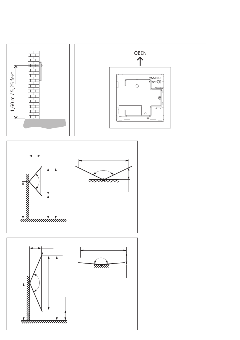
1 Empfohlene Einbauhöhe ca.
1,60 m bis Kameramitte.
2 Einbaulage der Kamera beachten,
die Typenbezeichnung muss auf der
Rückseite des Modules oben lesbar
sein.
3 Blickwinkel der Kamera mit einem
Öffnungswinkel von 130°
4 Blickwinkel der Kamera mit einem
Öffnungswinkel von 180°, im
Vollbildmodus.
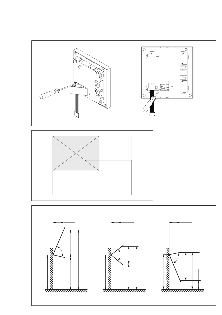
5 Der Blickwinkel der Kamera mit
einem Öffnungswinkel von 180°
kann je nach Einbausituation eingestellt werden. Klappe auf der
Rückseite des Moduls mit Hilfe eines
Schraubendrehers öffnen.
6 Gewünschten Bildausschnitt
(1 bis 9) oder Vollbild (0) am Drehschalter einstellen. Nachdem der
gewünschte Bildausschnitt eingestellt wurde, die Klappe schließen
und Modul einbauen.
7 Bildausschnitt anhand der vorliegenden Einbausituation wählen.
a Bildausschnitt (1-3)
Kameraausrichtung oben
b Bildausschnitt (4-6)
Kameraausrichtung Mitte
c Bildausschnitt (7-9)
Kameraausrichtung unten
Klemmenbelegung
BCM 653-.../BCM 658-...
TaK
In-Home-Bus: Video,
TbK
Kamerazweig
Ta TbAnschluss des
Türlautsprecher BTLM/BTLE
Vc
Ansteuerung vom Türlaut-
GND
sprecher für Kamera ein
b cVersorgung 12VAC
für Heizung
ACM 673-.../ACM 678-...
V1V2Videosignal
(Zweidraht FBAS)
V3V4Versorgung
der Kamera
V5V6Ansteuerung des
Videoausgangs
CM 613-.../CM 618-...
+M-MVersorgungsspannung Video
20–30 V DC
Vc-Ansteuerung vom Türlaut-
sprecher für Kamera ein
VKA Ansteuerung Kameraverteiler
–M wird geschaltet
A1A1potentialfreier Kontakt für
zusätzliche Anwendungen
bcVersorgung
12 V AC für Heizung
Koaxkabel
L
Leiter
S
Schirm
Installation
Installation und Inbetriebnahme
ist im jeweiligen Systemhandbuch
beschrieben.
4
Page 5

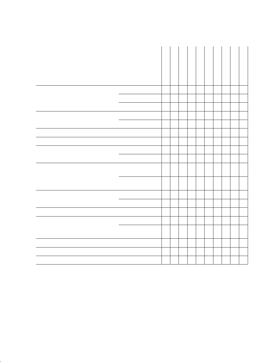
Technische Daten
Sprechsystem In-Home-Bus
Access
Systemfrei
Farbsystem PAL
NTSC
Bildaufnehmer CMOS-Sensor 1/3” 728 x 488 Pixel
1280 x 960 Pixel
Objektiv 2,1 mm
1,4 mm
Blickwinkel horizontal ca. 130°
vertikal ca. 100°
horizontal ca. 170°
vertikal ca. 135°
Auösung 520 TV-Linien
600 TV-Linien
Infrarotbeleuchtung integriert
2-stuge Heizung max. 100 mA
12 V AC
max. 130 mA
Schutzart IP54, IK10
Aufbauhöhe (mm) 15
Abmessungen (mm) B x H x T 99x99x41
BCM 653-0
BCM 658-0
ACM 673-0
ACM 678-0
CM 613-0
CM 618-0
BCM 653-1 USA
BCM 658-1 USA
CM 613-1 USA
X X X X
X X
X X X X
X X X X X X
X X X X
X X X X X
X X X X X
X X X X X
X X X X X
X X X X X
X X X X X
X X X X X
X X X X X
X X X X X X X X X X
X X
X X X X X X X X
X X X X X X X X X X
X X X X X X X X X X
X X X X X X X X X X
CM 618-1 USA
5
Page 6
English
Application
Wide-angle camera with a 130° or
180° angle of aperture, mounted in
Siedle Classic. Infrared lighting and
heating integrated.
Electrical voltage
Mounting, installation and servicing
work on electrical devices may only
be performed by a suitably qualied
electrician.
In the case of video systems, the following mounting situation must be
avoided at all costs:
• direct ajour light
• direct sunlight
• very bright image backgrounds
• highly reective walls opposite the
camera
• lamps or direct light sources
Mounting
1 Recommended mounting height
appr. 1.60m to centre camera.
2 Note the mounting position of the
camera, the type designation must
be legible at the top back of the
module.
3 Pick-up angle of the camera with
an angle of aperture of 130°
4 Pick-up angle of the camera with
an angle of aperture of 180° in the
full screen mode.
5 With an angle of aperture of 180°,
the pick-up angle of the camera
can be adjusted to any mounting
situation. Open the ap on the back
of the module with the aid of a
screwdriver.
6 Set the required picture excerpt
(1 to 9) or full screen (0) using the
rotary switch. Once the required picture excerpt has been set, close the
ap and mount the module.
7 Select the picture excerpt based
on the existing mounting situation.
a Picture excerpt (1-3) top camera
alignment
b Picture excerpt (4-6) central
camera alignment
c Picture excerpt (7-9) bottom
camera alignment
Terminal assignment
BCM 653-.../BCM 658-...
TaK
In-Home bus: Video,
TbK
camera branch
Ta TbConnection of the
BTLM/BTLE door loudspeaker
Vc
Actuation from the door
GND
loudspeaker to turn the
camera on
b c12VAC supply
for heating
ACM 673-.../ACM 678-...
V1V2video signal
(two-wire FBAS)
V3V4camera supply
V5V6Actuation of
video output
CM 613-.../CM 618-...
+M-MSupply voltage Video
20–30 V DC
Vc-Actuation from door loud-
speaker for camera on
VKA Actuation of camera
distributor –M is switched
A1A1Potential-free contact for
additional applications
bcPower supply 12 V AC
for heating
Coaxial cable
L
conductor
S
shield
Installation
Installation and commissioning are
described in the relevant system
manual.
6
Page 7
Specications
Intercom system In-Home bus
Access
System-free
Colour system PAL
NTSC
Image pick-up CMOS sensor 1/3" 728 x 488 pixel
1280 x 960 pixel
Lens 2.1 mm
1.4 mm
Aperture angle horizontal appr. 130°
vertical appr. 100°
horizontal appr. 170°
vertical appr. 135°
Resolution 520 TV-lines
600 TV-lines
Integrated lighting infrared
2-stage heating max. 100 mA
12 V AC
max. 130 mA
Protection system IP54, IK10
Height of structure (mm) 15
Dimensions (mm) W x H x D 99x99x41
w
BCM 653-0
BCM 658-0
ACM 673-0
ACM 678-0
CM 613-0
CM 618-0
BCM 653-1 USA
BCM 658-1 USA
CM 613-1 USA
X X X X
X X
X X X X
X X X X X X
X X X X
X X X X X
X X X X X
X X X X X
X X X X X
X X X X X
X X X X X
X X X X X
X X X X X
X X X X X X X X X X
X X
X X X X X X X X
X X X X X X X X X X
X X X X X X X X X X
X X X X X X X X X X
CM 618-1 USA
7
Page 8

Français
Application
Caméra grand angle avec angle
d’ouverture 130° ou 180°, intégrée
à Siedle Classic. Éclairage infrarouge
et chauffage intégrés.
Tension électrique
L’installation, le montage et l’entretien d’appareils électriques ne
doivent être réalisés que par un spécialiste en électricité.
Pour les installations vidéo, les situations de montage suivantes doivent
impérativement être évitées :
• un contre-jour direct
• le rayonnement direct du soleil
• un fond d’une grande luminosité
• des parois très rééchissantes des
parois très rééchissantes dans l’axe
de prise de vue de la caméra
• des lampes ou des sources de
lumière directe
Montage
1 Hauteur de montage conseillée
env. 1,60m du centre de la caméra.
2 Respecter la position de montage
de la caméra, la désignation du type
doit être lisible sur la face arrière du
module, en haut.
3 Angle de vision de la caméra, avec
un angle d’ouverture de 130°
4 Angle de vision de la caméra, avec
un angle d’ouverture de 180°, en
mode pleine image.
5 L’angle de vision de la caméra,
avec un angle d’ouverture de 180°,
peut être réglé en fonction de la
situation de montage. Ouvrir le
volet se trouvant en face arrière du
module, à l’aide d’un tournevis.
6 Régler la section d‘image souhaitée (1 à 9) ou régler Pleine image
(0) sur le commutateur rotatif. Une
fois que la section d‘image souhaitée
a été réglée, fermer le volet et
monter le module.
7 Choisir la section d‘image à l‘appui
de la situation de montage en présence.
a Section d‘image (1-3) orientation
de la caméra en haut
b Section d‘image (4-6) orientation
de la caméra au centre
c Section d‘image (7-9) orientation
de la caméra en bas
Implantation des bornes
BCM 653-.../BCM 658-...
TaK
Bus In-Home: Vidéo,
TbK
branche caméra
Ta TbRaccordement du portier
BTLM/BTLE
Vc
Activation du portier pour
GND
mise en marche de la caméra
b cAlimentation 12 V AC
pour chauffage
ACM 673-.../ACM 678-...
V1V2Signal vidéo
(FBAS deux ls)
V3V4Alimentation
de la caméra
V5V6Activation de la
sortie vidéo
CM 613-.../CM 618-...
+M-MTension d'alimentation vidéo
20–30 V DC
Vc-Activation du portier pour
mise en marche de la caméra
VKA Commutation de l'activation
du distributeur de la caméra
–M
A1A1Contact sans potentiel pour
applications complémentaires
bcAlimentation 12 V AC
pour chauffage
Câble coaxial
L
Conducteur
S
Blindage
Installation
L’installation et la mise en service
sont décrites dans le manuel système
correspondant.
8
Page 9

Caractéristiques techniques
Système interphonique Bus In-Home
Access
Sans système
Système couleur PAL
NTSC
Appareil de prise de vues capteur CMOS
1/3"
Objectif 2,1 mm
Angle de visée horizontal 130°
Résolution 520 TV-lignes
Eclairage infrarouge intégré
Chauffage 2 niveaux max. 100 mA
Indice de protection IP54, IK10
Epaisseur saillante (mm) 15
Dimensions (mm) l x H x P 99x99x41
728 x 488 pixels
1280 x 960 pixels
1,4 mm
vertical 100° environ
horizontal 170°
vertical 135° environ
600 TV-lignes
12 V AC
max. 130 mA
BCM 653-0
BCM 658-0
ACM 673-0
ACM 678-0
CM 613-0
CM 618-0
BCM 653-1 USA
BCM 658-1 USA
CM 613-1 USA
X X X X
X X
X X X X
X X X X X X
X X X X
X X X X X
X X X X X
X X X X X
X X X X X
X X X X X
X X X X X
X X X X X
X X X X X
X X X X X X X X X X
X X
X X X X X X X X
X X X X X X X X X X
X X X X X X X X X X
X X X X X X X X X X
CM 618-1 USA
9
Page 10

Italiano
Impiego
Telecamera grandangolo con angolo
di apertura di 130° o 180°, installata
in Siedle Classic. Illuminazione ad
infrarossi e riscaldamento integrati.
Tensione elettrica
Gli interventi di installazione, montaggio e assistenza agli apparecchi
elettrici devono essere eseguiti esclusivamente da elettricisti specializzati.
Negli impianti video occorre evitare
assolutamente le seguenti situazioni
di montaggio:
• in controluce diretta
• direttamente verso la luce del sole
• verso uno sfondo con intensa
luminosità
• verso pareti molto riettenti di
fronte la telecamera
• verso luci o fonti di luce dirette
Montaggio
1 Altezza di montaggio raccoman-
data circa 1,60 m no al centro della
telecamera.
2 Fare attenzione alla posizione
di montaggio della telecamera; la
denominazione del tipo deve essere
leggibile sul lato posteriore del
modulo in alto.
3 Angolo di ripresa della telecamera
con un angolo di apertura di 130°
4 Angolo di ripresa della telecamera
con un angolo di apertura di 180° in
modalità schermo intero.
5 L’angolo di ripresa della telecamera con un angolo di apertura di
180° può essere regolato in base alla
situazione di montaggio. Aprire lo
sportello sul retro del modulo con
l’ausilio di un cacciavite.
6 Sul selettore girevole impostare
la sezione d‘immagine desiderata
(1 – 9) oppure lo schermo interno
(0). Dopo aver impostato la sezione
d‘immagine desiderata, chiudere lo
sportello e montare il modulo.
10
7 Selezionare la sezione d‘immagine
in base alla posizione di montaggio
presente.
a Sezione d‘immagine (1-3) orientamento telecamera verso l‘alto
b Sezione d‘immagine (4-6) orientamento telecamera al centro
c Sezione d‘immagine (7-9) orientamento telecamera verso il basso
Assegnazione dei morsetti
BCM 653-.../BCM 658-...
TaK
In-Home-Bus: video,
TbK
derivazione della telecamera
Ta Tbcollegamento del
porter BTLM/BTLE
Vc
comando del porter per
GND
telecamera ON
b calimentazione 12VAC per
riscaldamento
ACM 673-.../ACM 678-...
V1V2Segnale video
(FBAS bilare)
V3V4Alimentazione della
telecamera
V5V6Comando
dell’uscita video
CM 613-.../CM 618-...
+M-Mtensione di alimentazione
video 20–30 V DC
Vc-comando del porter per tele-
camera ON
VKA comando distribuzione
telecamera –M attivato
A1A1contatto a potenziale zero per
applicazioni supplementari
bcalimentazione 12 V AC per
riscaldamento
Cavo coassiale
L
Conduttori
S
Schermatura
Installazione
L’installazione e la messa in funzione
sono descritte nel rispettivo manuale
del sistema.
Page 11

Dati tecnici
Sistema citofonico In-Home-Bus
Access
Senza sistema
Sistema colori PAL
NTSC
Ripresa immagini sensore
CMOS 1/3"
Obiettivo 2,1 mm
Angolo di ripresa orizzontale circa 130°
Risoluzione 520 TV-linee
Illuminazione agli infrarossi integrata
Riscaldamento a 2 livelli max. 100mA
Classe di protezione IP54, IK10
Altezza di montaggio (mm) 15
Dimensioni (mm) Larg. x Alt. x Prof. 99x99x41
728 x 488 pixel
1280 x 960 pixel
1,4 mm
verticale circa 100°
orizzontale circa 170°
verticale circa 135°
600 TV-linee
12VAC
max. 130mA
BCM 653-0
BCM 658-0
ACM 673-0
ACM 678-0
CM 613-0
CM 618-0
BCM 653-1 USA
BCM 658-1 USA
CM 613-1 USA
X X X X
X X
X X X X
X X X X X X
X X X X
X X X X X
X X X X X
X X X X X
X X X X X
X X X X X
X X X X X
X X X X X
X X X X X
X X X X X X X X X X
X X
X X X X X X X X
X X X X X X X X X X
X X X X X X X X X X
X X X X X X X X X X
CM 618-1 USA
11
Page 12

Nederlands
Toepassing
Breedhoekcamera met 130° of 180°
openingshoek, ingebouwd in Siedle
Classic. Infrarood verlichting en verwarming geïntegreerd.
Elektrische spanning
Inbouw, montage en onderhoudswerkzaamheden aan elektrische
apparaten mogen uitsluitend door
een elektro-vakman worden uitgevoerd.
B video-installaties moeten de volgende inbouwsituaties absoluut vermeden worden:
• direct tegenlicht
• directe zonnestralen
• achtergrondbeeld met grote felheid
• sterk reecterende muren tegenover de kamera
• lampen resp. directe lichtbronnen
Montage
1 Aanbevolen inbouwhoogte ca.
1,60m tot midden van de camera.
2 Let op de inbouwpositie van de
camera, de type-aandiuding moet
op de achterkant van de module
boven te lezen zn.
3 Beeldhoek van de camera met een
openingshoek van 130°
4 Beeldhoek van de camera met een
openingshoek van 180°, in de volledige beeld modus.
5 De beeldhoek van de camera met
een openingshoek van 180° kan
afhankelk van de inbouwsituatie
worden ingesteld. Klep op de ach-
terzde van de module met behulp
van een schroevendraaier openen.
6 Gewenste beelduitsnede (1 tot 9)
of volledig beeld (0) met de draaischakelaar instellen. Nadat de
gewenste beelduitsnede is ingesteld, de klep sluiten en module
inbouwen.
7 Beelduitsnede aan de hand van de
geldende inbouwsituatie kiezen.
a Beelduitsnede (1-3) camera-uitrichting boven
b Beelduitsnede (4-6) camerauitrichting midden
c Beelduitsnede (7-9) camera-uitrichting beneden
Klemmenindeling
BCM 653-.../BCM 658-...
TaK
In-Home-Bus: Video,
TbK
cameratak
Ta Tbaansluiting van de deurliud-
spreker BTLM/BTLE
Vc
aansturing van de
GND
deurluidspreker voor
camera in
b cverzorging 12VAC voor
verwarming
ACM 673-.../ACM 678-...
V1V2videosignaal
(tweedraads FBAS)
V3V4verzorging van
de camera
V5V6aansturing van
de video uitgang
CM 613-.../CM 618-...
+M-Mverzorgingsspanning
video 20–30 V DC
Vc-aansturing van de deurluid-
spreker voor camera in
VKA aansturing cameraverdeler
–M wordt geschakeld
A1A1potentiaalvr contact voor
extra toepassingen
bcverzorging 12 V AC voor
verwarming
Coaxkabel
L
geleider
S
scherm
Installatie
Installatie en ingebruikname is
steeds in het betreffende systeemhandboek omschreven.
12
Page 13

Technische gegevens
Spraaksysteem In-Home-Bus
Access
Systeemvr
Kleurensysteem PAL
NTSC
Beeldopname CMOS-sensor 1/3” 728 x 488 pixels
1280 x 960 pixels
Objectief 2,1 mm
1,4 mm
Blikhoek horizontaal ca. 130°
verticaal ca. 100°
horizontaal ca. 170°
verticaal ca. 135°
Resolutie 520 TV-lnen
600 TV-lnen
Infrarood verlichting geïntegreerde
verwarming 2-traps max. 100mA
12VAC
max. 130mA
Beschermingsklasse IP54, IK10
Opbouwhoogte (mm) 15
Afmetingen (mm) B x H x D 99x99x41
BCM 653-0
BCM 658-0
ACM 673-0
ACM 678-0
CM 613-0
CM 618-0
BCM 653-1 USA
BCM 658-1 USA
CM 613-1 USA
X X X X
X X
X X X X
X X X X X X
X X X X
X X X X X
X X X X X
X X X X X
X X X X X
X X X X X
X X X X X
X X X X X
X X X X X
X X X X X X X X X X
X X
X X X X X X X X
X X X X X X X X X X
X X X X X X X X X X
X X X X X X X X X X
CM 618-1 USA
13
Page 14

Dansk
Anvendelse
Vidvinkelkamera med 130° eller
180° åbningsvinkel, indbygget i
Siedle Classic. Infrarødbelysning og
varme integreret.
Elektrisk spænding
Indbygning og montering af samt
servicearbejde på elektrisk materiel
må kun foretages af en aut. elinstallatør.
Ved videoanlæg er det vigtigt, at følgende monteringssituationer
undgås:
• direkte modlys
• direkte sollys
• meget lys baggrund
• kraftigt reekterende mure på
modsat side af kameraet
• belysningsmoduler eller direkte
lyskilder
Montage
1 Anbefalet indbygningshøjde ca.
1,60 m til kameraets midte.
2 Vær opmærksom på kameraets
indbygningsposition, typebetegnelsen skal kunne læses øverst på
modulets bagside.
3 Kameraets blikvinkel med en
åbningsvinkel på 130°
4 Kameraets blikvinkel med en
åbningsvinkel på 180°, i funktionen
fuld skærm.
5 Kameraets blikvinkel med en
åbningsvinkel på 180° kan indstilles
afhængigt af indbygningssituationen. Klap bag på modul åbnes vha.
en skruetrækker.
6 Ønsket billedudsnit (1 til 9) eller
fuld skærm (0) indstilles med drejekontakt. Når det ønskede billedudsnit er indstillet, lukkes klappen, og
modulet indbygges.
7 Billedudsnit vælges på basis af den
aktuelle indbygningssituation.
a Billedudsnit (1-3) kameraindstilling oppe
b Billedudsnit (4-6) kameraindstilling
i midten
c Billedudsnit (7-9) kameraindstilling nede
Klemmekonguration
BCM 653-.../BCM 658-...
TaK
In-Home-Bus: Video,
TbK
kameraafgrening
Ta TbTilslutning af dørstationen
BTLM/BTLE
Vc
Aktivering af kameraet
GND
fra dørstationen
b c12 V AC-strømforsyning
til varmelegemet
ACM 673-.../ACM 678-...
V1V2Videosignal
(totråds FBAS)
V3V4Forsyning til kameraet
V5V6Styring af videoudgangen
CM 613-.../CM 618-...
+M-MForsyningsspænding
til video 20–30 V DC
Vc-Aktivering af kameraet
fra dørstationen
VKA Styring af kamerafordeler, –M
kobles
A1A1Potentialfri kontakt til
yderligere anvendelser
bc12 V AC-strømforsyning
til varmelegemet
Koaksialkabel
L
leder
S
skærm
Installation
Installation og ibrugtagning er
beskrevet i den enkelte systemmanual.
14
Page 15

Tekniske data
Samtalesystem In-Home-bus
Access
Systemfri
Farvesystem PAL
NTSC
Kamera CMOS-sensor 1/3" 728 x 488 pixel
1280 x 960 pixel
Objektiv 2,1 mm
1,4 mm
Betragtningsvinkel horisontal ca. 130°
vertikal ca. 100°
horisontal ca. 170°
vertikal ca. 135°
Opløsning 520 TV-linjer
600 TV-linjer
Infrarød belysning integreret
2-trins varmeelement maks. 100mA
12VAC,
maks. 130mA
Kapslingsklasse IP54, IK10
Frembygningsdybde (mm) 15
Mål (mm) b x h x d 99x99x41
BCM 653-0
BCM 658-0
ACM 673-0
ACM 678-0
CM 613-0
CM 618-0
BCM 653-1 USA
BCM 658-1 USA
CM 613-1 USA
X X X X
X X
X X X X
X X X X X X
X X X X
X X X X X
X X X X X
X X X X X
X X X X X
X X X X X
X X X X X
X X X X X
X X X X X
X X X X X X X X X X
X X
X X X X X X X X
X X X X X X X X X X
X X X X X X X X X X
X X X X X X X X X X
CM 618-1 USA
15
Page 16

Svenska
Användning
Vidvinkelkamera med en öppningsvinkel på 130° eller 180°, monterad
i Siedle Classic. Integrerad infraröd
belysning och värme.
Elektrisk spänning
Installation, montering och servicearbeten på elektriska apparater får
utföras endast av behörig eltekniker.
Vid videoanläggningar måste ovillkorligen följande monteringssituationer undvikas:
• Direkt motljus
• Direkt solsken
• Bildbakgrund med stor ljusstyrka
• Starkt reekterande väggar som
benner sig mittemot kameran
• Lampor resp. direkta ljuskällor
Montage
1 Rekommenderad monteringshöjd
ca 1,60 m till mitten på kameran.
2 Beakta kamerans position vid
monteringen, typbeteckningen
måste kunna läsas upptill på
modulens baksida.
3 Blickvinkeln till kameran med en
öppningsvinkel på 130°
4 Blickvinkeln till kameran med en
öppningsvinkel på 180°, i helbildsläget.
5 Blickvinkeln till kameran med en
öppningsvinkel på 180° kan ställas
in i förhållande till monteringssituationen. Öppna luckan på baksidan av
modulen med hjälp av en skruvmejsel.
6 Ställ in önskat bildavsnitt (1 till 9)
eller helbild (0) med vridomkopplaren. När det önskade bildavsnittet är inställt, stäng luckan
och montera modulen igen.
7 Välj bildavsnittet i förhållande till
den aktuella monteringssituationen.
a Bildavsnitt (1-3) kamerariktning
uppe
b Bildavsnitt (4-6) kamerariktning
i mitten
c Bildavsnitt (7-9) kamerariktning
nere
Klämtilldelning
BCM 653-.../BCM 658-...
TaK
In-Home-buss: Video,
TbK
kameragren
Ta TbAnslutning för dörrhögtalare
BTLM/BTLE
Vc
Aktivering av dörrhögtalaren
GND
när kameran är på
b cFörsörjnin 12 V AC
för värmen
ACM 673-.../ACM 678-...
V1V2Videosignal (tvåtråds FBAS)
V3V4Försörjning av kameran
V5V6Aktivering av videoutgången
CM 613-.../CM 618-...
+M-MFörsörjningsspänning video
20–30 V DC
Vc-Aktivering av dörrhögtalaren
när kameran är på
VKA Aktiveringen av kameraförde-
laren –M kopplas
A1A1Potentiallös kontakt för ytter-
ligare användningar
bcFörsörjning 12 V AC
för värmen
Koaxialkabel
L
ledare
S
skärm
Installation
Installationen och idrifttagningen är
beskrivna i respektive systemhandbok.
16
Page 17

Tekniska data
Talsystem In-Home-buss
Access
Systemfri
Färgsystem PAL
NTSC
Bildupptagare CMOS-sensor 1/3" 728 x 488 pixel
1280 x 960 pixel
Objektiv 2,1 mm
1,4 mm
Betragtningsvinkel horisontal ca. 130°
vertikal ca. 100°
horisontal ca. 170°
vertikal ca. 135°
Upplösning 520 TV-linjer
600 TV-linjer
Infrarød belysning integreret
2-trins varmeelement maks. 100mA
12VAC,
maks. 130mA
Skyddstyp IP54, IK10
Konstruktionshöjd (mm) 15
Mått (mm) B X H X D 99x99x41
BCM 653-0
BCM 658-0
ACM 673-0
ACM 678-0
CM 613-0
CM 618-0
BCM 653-1 USA
BCM 658-1 USA
CM 613-1 USA
X X X X
X X
X X X X
X X X X X X
X X X X
X X X X X
X X X X X
X X X X X
X X X X X
X X X X X
X X X X X
X X X X X
X X X X X
X X X X X X X X X X
X X
X X X X X X X X
X X X X X X X X X X
X X X X X X X X X X
X X X X X X X X X X
CM 618-1 USA
17
Page 18

Español
Aplicación
Cámara de gran angular con apertura angular de 130° o 180°, montada en Siedle Classic. Iluminación
por infrarrojos y calefacción integradas.
Tensión eléctrica
La integración, montaje y los trabajos de servicio en aparatos eléctricos deben ser realizados exclusivamente por electricistas
especializados.
En instalaciones de vídeo, es absolutamente imprescindible evitar las
siguientes situaciones de montaje:
• Contraluz directa
• Radiación solar directa
• Fondo de imagen con gran luminosidad
• Paredes muy reectantes en el
lado opuesto de la cámara
• Lámparas o fuentes de luz directas
Montaje
1 Altura de montaje recomendada
aprox. 1,60 m hasta el centro de la
cámara.
2 Tener presente la posición de
montaje de la cámara y asegurarse
de que la designación de modelo sea
legible en la parte superior del lado
posterior del módulo.
3 Ángulo de visión de la cámara con
una apertura angular de 130°
4 Ángulo de visión de la cámara con
una apertura angular de 180°, en
modo de pantalla completa.
5 El ángulo de visión de la cámara
con una apertura angular de 180° se
puede ajustar en función de la situación de montaje. Abrir la tapa articulada del lado posterior del módulo
con ayuda de un destornillador.
18
6 Congurar el encuadre deseado
(1 hasta 9) o pantalla completa (0)
con el selector giratorio. Después
de haber congurado el encuadre
deseado, cerrar la tapa articulada y
montar el módulo.
7 Seleccionar el encuadre en función
de la situación de montaje existente.
a Encuadre (1-3) orientación de la
cámara arriba
b Encuadre (4-6) orientación de la
cámara centro
c Encuadre (7-9) orientación de la
cámara abajo
Funciones de los bornes
BCM 653-.../BCM 658-...
TaK
Bus In-Home: vídeo,
TbK
ramal de videocámara
Ta TbConexión del altavoz de
puerta BTLM/BTLE
Vc
Control desde el altavoz
GND
de puerta para encender la
cámara
b cAlimentación de 12VAC
para la calefacción
ACM 673-.../ACM 678-...
V1V2Señal de vídeo
(FBAS bilar)
V3V4Alimentación eléctrica
de la cámara
V5V6Control de la salida
de vídeo
CM 613-.../CM 618-...
+M-MTensión de alimentación de
vídeo 20-30 V DC
Vc-Control desde el altavoz
de puerta para encender la
cámara
VKA Se conmuta el control del
distribuidor para cámara -M
A1A1Contacto libre de potencial
para aplicaciones adicionales
bcAlimentación de 12 V AC
para la calefacción
Cable coaxial
L
conductor
S
apantallamiento
Instalación
La instalación y la puesta en servicio
se describen en el manual del sistema pertinente.
Page 19

Características técnicas
Sistema de interfonía Bus In-Home
Access
Libre de sistema
Sistema de color PAL
NTSC
Sensor de imagen Sensor
CMOS de 1/3"
Objetivo 2,1 mm
Ángulo de visión horizontal aprox. 130°
Resolución 520 TV-líneas
Iluminación por infrarrojos integrada
Calefacción de 2 niveles máx. 100mA
Grado de protección IP54, IK10
Altura de montaje (mm) 15
Dimensiones (mm) An x Al x Pr 99x99x41
728 x 488 píxeles
1280 x 960 píxeles
1,4 mm
vertical aprox. 100°
horizontal aprox. 170°
vertical aprox. 135°
600 TV-líneas
12VAC
máx. 130mA
BCM 653-0
BCM 658-0
ACM 673-0
ACM 678-0
CM 613-0
CM 618-0
BCM 653-1 USA
BCM 658-1 USA
CM 613-1 USA
X X X X
X X
X X X X
X X X X X X
X X X X
X X X X X
X X X X X
X X X X X
X X X X X
X X X X X
X X X X X
X X X X X
X X X X X
X X X X X X X X X X
X X
X X X X X X X X
X X X X X X X X X X
X X X X X X X X X X
X X X X X X X X X X
CM 618-1 USA
19
Page 20

Polski
Zastosowanie
Kamera szerokokątna z kątem
aperturowym 130° lub 180°, zabudowana w systemie Siedle Classic.
Ze zintegrowanym podświetleniem
podczerwienią i ogrzewaniem.
Napięcie elektryczne
Wbudowanie, montaż i prace serwisowe na urządzeniach elektrycznych
może wykonywać jedynie upraw-
niony elektryk.
W przypadku instalacji wideo należy
unikać następujących sytuacji:
• bezpośrednio padające światło
• bezpośrednie nasłonecznienie
• tło obrazu o bardzo dużej jasności
• silnie odbijające ściany po przeciwnej stronie kamery
• lampy lub bezpośrednie źródła
światła
Montaż
1 Zalecana wysokość montażowa
ok. 1,60 m od środka kamery.
2 Zwrócić uwagę na prawidłową
pozycję montażową kamery, oznaczenie typu musi być widoczne na
tylnej ściance modułu u góry.
3 Kąt widzenia kamery z kątem
aperturowym 130°
4 Kąt widzenia kamery z kątem
aperturowym 180°, w trybie pełno-
ekranowym.
5 Kąt widzenia kamery z kątem
aperturowym 180° można regulować w zależności od warunków
montażowych. Otworzyć klapę z tyłu
modułu przy pomocy śrubokręta.
6 Na przełączniku obrotowym
ustawić żądany fragment obrazu
(1 do 9) albo pełny obraz (0). Po
ustawieniu żądanego fragmentu
obrazu zamknąć klapę i zamontować moduł.
7 Fragment obrazu wybrać odpowiednio do warunków montażo-
wych na miejscu.
a Fragment obrazu (1-3) ustawienie
kamery w górę
b Fragment obrazu (4-6) ustawienie
kamery na środku
c Fragment obrazu (7-9) ustawienie
kamery na dół
Podłączenie zacisków
BCM 653-.../BCM 658-...
TaK
In-Home-Bus: wideo,
TbK
obwód kamery
Ta TbPodłączenie głośnika przy-
drzwiowego BTLM/BTLE
Vc
Zasterowanie z głośnika
GND
przydrzwiowego włączania
kamery
b cZasilanie ogrzewania
napięciem 12 V AC
ACM 673-.../ACM 678-...
V1V2sygnał wideo
(kabel dwużyłowy FBAS)
V3V4zasilanie kamery
V5V6zasterowanie wyjścia
wideo
CM 613-.../CM 618-...
+M-MNapięcie zasilania kamery
wideo 20-30 V DC
Vc-Zasterowanie z głośnika
przydrzwiowego włączania
kamery
VKA Zasterowanie rozdzielczość
kamery –M jest włączana
A1A1zestyk bezpotencjałowy dla
dodatkowych zastosowań
bczasilanie ogrzewania
napięciem zmiennym 12 V
kabel koncentryczny
L
przewód
S
ekran
Instalacja
Instalacja i uruchomienie opisane są
w odpowiednim podręczniku obsługi
systemu.
20
Page 21

Dane techniczne
System domofonowy In-Home-Bus
Access
bezsystemowa
System nadawania koloru PAL
NTSC
Przetwornik obrazu
CMOS-sensor 1/3"
Obiektyw 2,1 mm
Pole widzenia w poziomie ok. 130°
Rozdzielczość 520 TV linii
Podświetlenie podczerwienią zintegrowane
2-stopniowe ogrzewanie max. 100mA
stopień ochrony IP54, IK10
Wysokość montażu (mm) 15
wymiary (mm) szer. x wys. x gł. 99x99x41
728 x 488 pikseli
1280 x 960 pikseli
1,4 mm
w pionie ok. 100°
w poziomie ok. 170°
w pionie ok. 135°
600 TV linii
12VAC,
max. 130mA
BCM 653-0
BCM 658-0
ACM 673-0
ACM 678-0
CM 613-0
CM 618-0
BCM 653-1 USA
BCM 658-1 USA
CM 613-1 USA
X X X X
X X
X X X X
X X X X X X
X X X X
X X X X X
X X X X X
X X X X X
X X X X X
X X X X X
X X X X X
X X X X X
X X X X X
X X X X X X X X X X
X X
X X X X X X X X
X X X X X X X X X X
X X X X X X X X X X
X X X X X X X X X X
CM 618-1 USA
21
Page 22

русский
Область применения
Широкоугольная камера с углом
охвата 130° или 180°, установленная в Siedle Classic. Встроенное
инфракрасное освещение и обогрев.
Электрическое напряжение
Встраивание, монтаж и обслуживание электроприборов разрешается выполнять только квалифицированным электрикам.
Следующих ситуаций при монтаже видеосистем необходимо
избегать:
• прямой свет, падающий с противоположной стороны
• прямые солнечные лучи
• фон с большой яркостью
• интенсивно отражающие стены
на противоположной от камеры
стороне
• светильники и источники прямого света
Монтаж
1 Рекомендуемая высота мон-
тажа: ок. 1,60 м до центра
камеры.
2 Учитывать монтажное положение камеры, обозначение типа
должно располагаться вверху на
задней панели модуля.
3 Угол обзора камеры с углом
охвата 130°
4 Угол обзора камеры с углом
охвата 180°, в полноэкранном
режиме.
5 Угол обзора камеры с углом
охвата 180° можно настроить
в зависимости от варианта
монтажа. С помощью отвертки
открыть крышку на задней стороне модуля.
6 Настроить требуемый сегмент
изображения (1 – 9) или полное
изображение (0) поворотным
переключателем. После того, как
требуемый сегмент изображения
был настроен, закрыть крышку и
установить модуль.
7 Выбрать сегмент изображения,
основываясь на имеющемся варианте монтажа.
a Сегмент изображения (1-3) –
ориентация камеры вверх
b Сегмент изображения (4-6) –
ориентация камеры по центру
c Сегмент изображения (7-9) –
ориентация камеры вниз
Разводка клемм
BCM 653-.../BCM 658-...
TaK
In-Home-Bus: Видео,
TbK
ответвление камеры
Ta TbПодключение дверного
громкоговорителя
BTLM/BTLE
Vc
Активирование включения
GND
камеры от дверной
аудиопанели
b cЭлектропитание
12 В перем. тока для
нагревателя
ACM 673-.../ACM 678-...
V1V2Видеосигнал (двухпрово-
дная схема FBAS)
V3V4Электропитание
камеры
V5V6Активирование
видеовыхода
CM 613-.../CM 618-...
+M-MЭлектропитание видео
20-30 В пост. тока
Vc-Активирование включения
камеры от дверной
аудиопанели
VKA Включается управление
распределителем камер –M
A1A1Контакт с нулевым потен-
циалом для дополнительного оборудования
bcЭлектропитание
12 В перем. тока для
нагревателя
Коаксиальный кабель
L
Провод
S
Экран
Монтаж
Монтаж и ввод в эксплуатацию
описаны в соответствующем
системном руководстве.
22
Page 23

Технические данные
Переговорная система Шина, установленная
Стандарт PAL
Датчик изображения формирователь
видеосигналов на К-МОП 1/3"
Объектив 2,1 мм
Угол обзора по горизонтали ок. 130°
Степень разрешения 520 линий
Инфракрасное освещение интегрировано
2-ступенчатый нагрев макс. 100 мА
Тип защиты IP 54, IK 10
Высота установки (мм) 15
Размеры (мм) Ш x В x Г 99x99x41
внутри помещения
Access
Внесистемный
NTSC
728 x 488 пикселей
1280 x 960 пикселей
1,4 мм
по вертикали ок. 100°
по горизонтали ок. 170°
по вертикали ок. 135°
600 линий
12 В ~,
макс. 130 мА
BCM 653-0
BCM 658-0
ACM 673-0
ACM 678-0
CM 613-0
CM 618-0
BCM 653-1 USA
BCM 658-1 USA
CM 613-1 USA
X X X X
X X
X X X X
X X X X X X
X X X X
X X X X X
X X X X X
X X X X X
X X X X X
X X X X X
X X X X X
X X X X X
X X X X X
X X X X X X X X X X
X X
X X X X X X X X
X X X X X X X X X X
X X X X X X X X X X
X X X X X X X X X X
CM 618-1 USA
23
Page 24

S. Siedle & Söhne
Telefon- und Telegrafenwerke OHG
Postfach 1155
78113 Furtwangen
Bregstraße 1
78120 Furtwangen
Telefon +49 7723 63-0
Telefax +49 7723 63-300
www.siedle.de
info@siedle.de
© 2014/07.14
Printed in Germany
Best. Nr. 0-1101/048690
 Loading...