

Page 1
SM800, Assembly Manual
PCB Version 1.1
358
G6753
334
Page 2
SM800, Assembly Manual
PCB Version 1.1
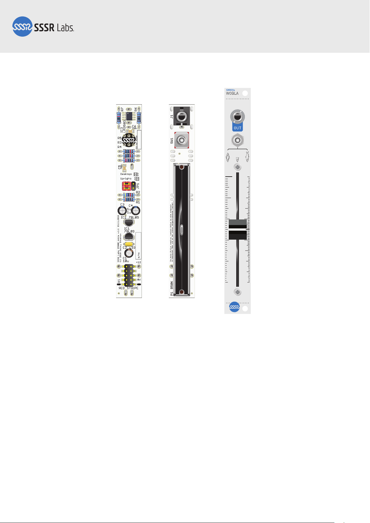
Step 1: PCB
The SM800 DIY Kit contains only one board. Most of the components have to be
installed on the REAR side. Short instructions: please assemble the module in the
following order: Solder the SMD chip (as shown on the picture), SMD capacitors, resistors, 330 nF capacitor, power header, configuration header. Push all pins of the configuration header completely into the hole. Solder the electrolytic capacitors, voltage regulators. Important: Trim all pins sticking up inside the potentiometer footprint flush to
the joints with a flush cutters! Clean the PCB. Solder the socket, the switch and the
potentiometer. Wear one nut on the switch. Put two spacers on the pot's threaded
holes. Install the panel. Gently tighten the potentiometer mounting screws through the
spacers by 2-3 turns. Wear and firmly tighten the nuts on the socket and switch. Adjust
the pot mounting screws tension. If you need more details, the following pages will
guide you through this process.
Page 2 of 9
Page 3

SM800, Assembly Manual
PCB Version 1.1
Step 2: SMD components
358
G6753
358
G6753
Start with soldering the LM358 chip. Place it as shown in the picture, accurately
aligned to its footprint, then solder just the pin 1. Adjust the orientation of the chip with
a pair of tweezers, keeping the solder melted, then let it cool down and solder the
opposite pin 5. If orientation is alright, solder the remaining pins. Solder the SMD
capacitors the similar way. These components are not polarized.
Page 3 of 9
Page 4

SM800, Assembly Manual
PCB Version 1.1
358
G6753
334
334
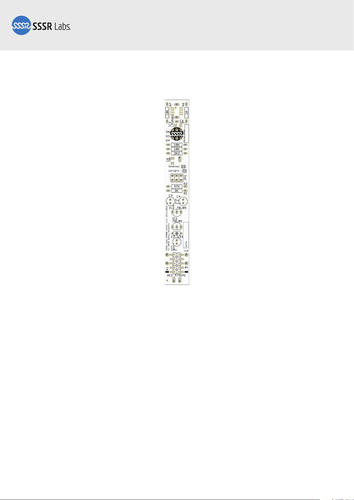
Step 3: Resistors, ceramic capacitor, power header
Install the resistors. You can use the above picture as the reference to verify values
before soldering. Solder all resistors from the top.
Install the 330 nF ceramic capacitor. It's not polarized. Flip the PCB over, solder the
capacitor and reflow some of resistors, which have their pads not completely covered
with the solder.
Now return to the other side and solder the power header, using the same technique
as used with the chip.
Page 4 of 9
Page 5

SM800, Assembly Manual
PCB Version 1.1
358
G6753
334
HEAT MELT PUSH
Step 4: Configuration header
Solder the configuration header. You can put on the power cable to prevent the header
pins from moving during soldering. The plastic base is tend to melt. After soldering all
pins, you additionally need to push each pin completely into its hole in order to leave
this area of the PCB a flat plane. It can be easily performed by forced pushing them
with the tip of the soldering iron.
Page 5 of 9
Page 6

SM800, Assembly Manual
PCB Version 1.1
358
G6753
334
78L05
78L09
Step 5: Electrolytic capacitors and power regulators
Install the electrolytic capacitors as shown on the picture, following the polarity. There
is only one 10 uF capacitor and two 1 uF capacitors in the kit. Install the power regulators, 78L05 and 78L09.
Now you can trim the pins sticking up from the PCB. The slider potentiometer has to
be installed on the top side of the PCB and its base will be very close to the surface, so
you need to flush trim all pins in potentiometer's area shown by the footprint. This
can't be done with a symmetrical cutters, so please use the special flush cutters for
this. If you do not have a flush cutters, trim the pins, then melt the joints and elevate
the components to drag and hide the pins into its holes. Now you can clean the PCB
your most preferred way, including complete immersion in cleaning solution.
Page 6 of 9
Page 7

SM800, Assembly Manual
PCB Version 1.1
Install all hardware on the FRONT side of the PCB!
Step 6: Panel hardware
Install and solder the jack socket, the mode switch and the sliding potentiometer. You
do not yet need to install the front panel. Just make sure that all components are
installed straight and firmly, and solder them. If you want to wipe the flux off the PCB,
do this gently not letting your solution to get inside the mechanical parts.
Page 7 of 9
Page 8

SM800, Assembly Manual
PCB Version 1.1
Step 7: Front panel
As you can see, all components have different heights. We need to compensate this by
placing spacers between the front panel and too low parts.
Screw on and tighten the first nut on the switch. Now gently place two PVC spacers on
the threaded holes of the potentiometer. If spacers have a bit different height, set the
tallest one closer to the edge. Now gently put on the front panel. Holding the panel
pressed down to the spacers, adjust position of the spacers if needed, and put the
M2x7 screws through the panel and spacers and tighten them by 2-3 turns.
Now, put on and firmly tighten the remaining nuts. After that, adjust the tension of the
potentiometer mounting screws to just pull the potentiometer to the panel and establish some friction, preventing screws from unscrewing. Put on the slider cap.
Page 8 of 9
Page 9

SM800, Assembly Manual
PCB Version 1.1
358
G6753
358
G6753
358
G6753
358
G6753
358
G6753
334
334
334
334
334
If you would like to use an array of Wobla
modules with a single power connector, you
can connect them together with a jumper
SM800a (Desktop) SM800b (Upright)
wires, using the holes next to the power
connector. +12 goes to +12, GND goes to GND.
Step 8: Installing the jumpers
The position of two jumpers depends on the panel type in your kit, and the desired
orientation of the module. By default, configuration for SM800a is Desktop, and for
SB800b is Upright. This way, the zero point of the slider will be at the bottom, with
respect to the labels on the panel. You can reverse this by setting the jumpers to the
opposite position.
That's all, folks! The module does not need any adjustment and ready to use. Thank
you for reading the instructions and purchasing this SSSR Labs DIY kit!
Page 9 of 9
 Loading...