

Page 1
180
180
20.000
1n
1n
.1 uF
.1 uF
.1 uF
.1 uF
.1 uF
.1 uF
.1 uF
.1 uF
.1 uF
SN74HC595
SN74HC595
SSSR Labs MCU Chip
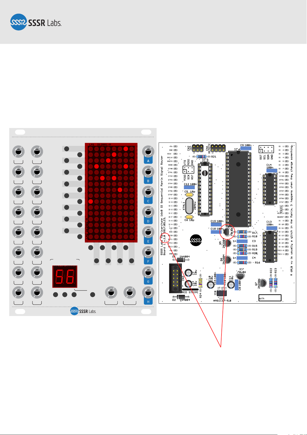
MATRIXARCHATE 1.0
MT8816AE
MATRIXARCHATE SM010
16×8 IO SEQUENTIAL MATRIX SIGNAL ROUTER
1
2
3
4
5
6
7
8
9
10
11
12
13
14
15
16
A B C D E F G H
15
16
13 14
11 12
9 10
7 8
5 6
3 4
1 2
PREV SAVE SETUP/EXITNEXT
PROGRAM
STEP RESET
−10 REVERT CLEAR+10
[ LOCK ]
f2f1
SM010, Assembly Manual
PCB Version 1.0
DON’T SHOOT YOURSELF IN THE FOOT!
PCB VERSION 1.0:
PLEASE READ PAGE 15 CAREFULLY!
Page 2
SM010, Assembly Manual
PCB Version 1.0
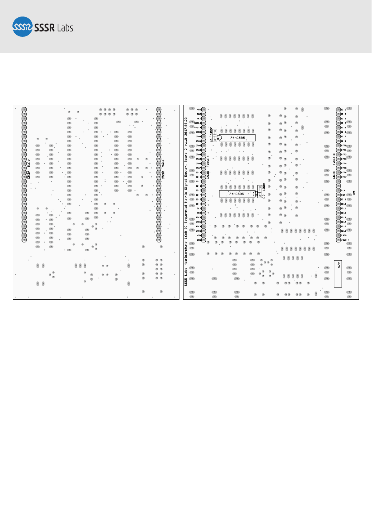
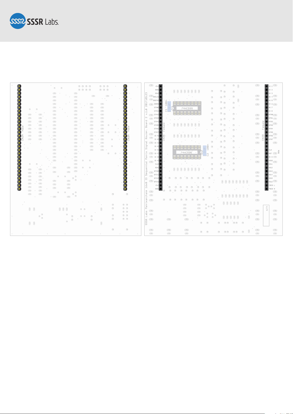
Step 1: PCB Bottom side
The SM010 DIY Kit contains two boards:
Board 1. (Rear) This board contains the power connector, microcontroller, and the
matrix switch chip.
Board 2. (Front) This board is entirely dedicated to the interface.
Most of the components have to be placed on the top side of both boards, but you must
start with soldering the back side — the one shown above. It is used for pin-headers,
which connect boards together, and for two shift registers handling the LED matrices.
You could speed up the building process using a tool holding the boards firmly during
stuffing and soldering.
Page 2 of 22
Page 3
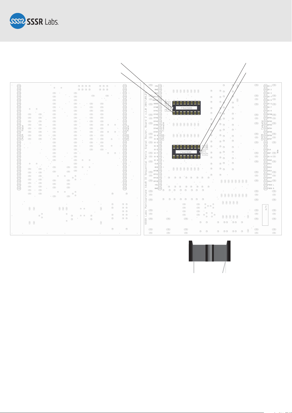
Notch
SM010, Assembly Manual
PCB Version 1.0
Pin 1
Pin 1
Notch
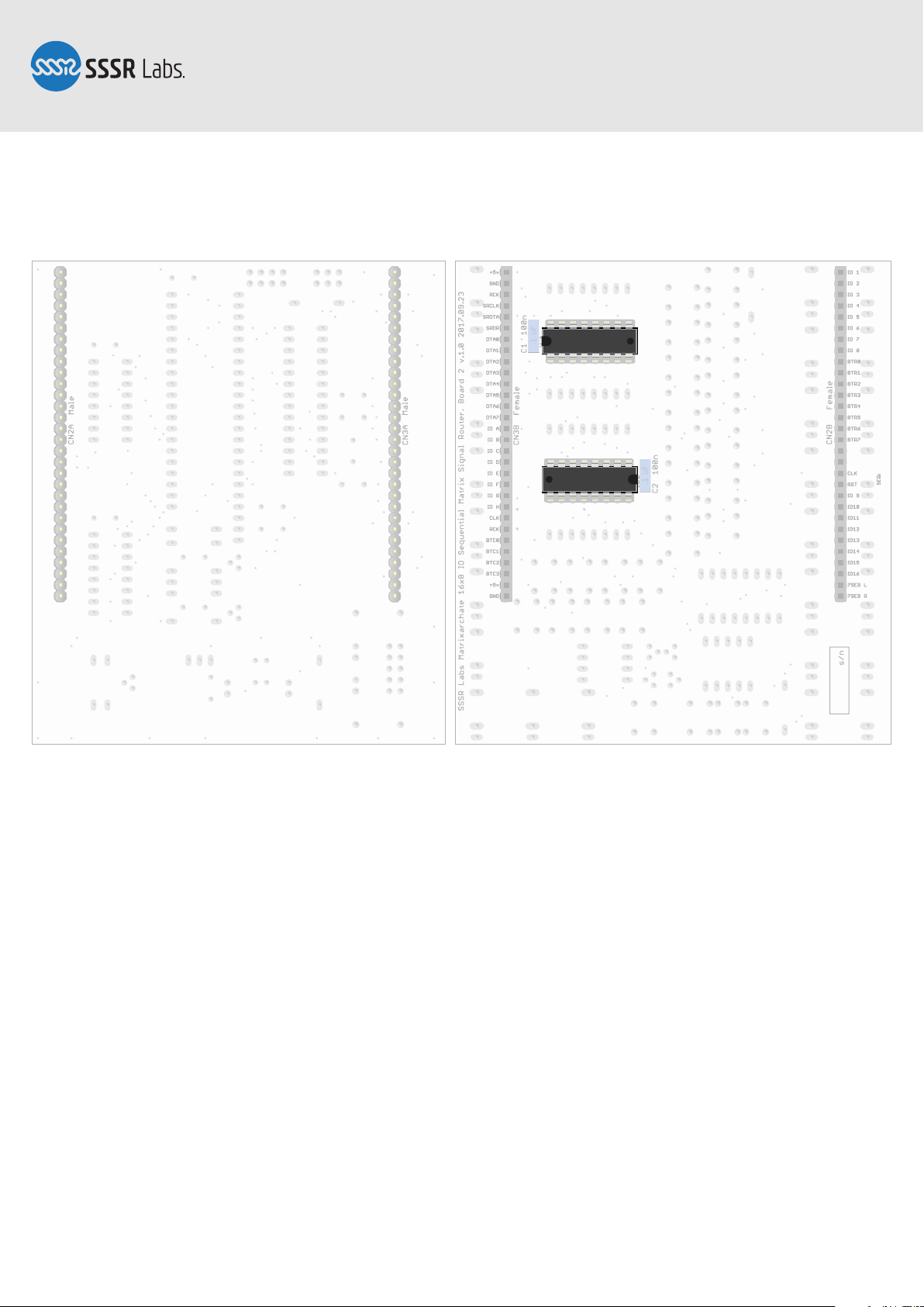
Step 2: IC Sockets for the board 2
Insert two DIP IC sockets. Please pay attention to the correct orientation, which is
different for this particular sockets!
These sockets tend to slip off the holes, so it’s practical to gently bend their pins
towards each other to help them fit in the holes while you’re flipping the board over
and soldering them. It’s recommended to solder just two pins in the diagonally opposite corners of each socket and then, if needed, reflow them while pushing the socket
closer to the surface of the PCB. Then solder the rest of the pins.
Page 3 of 22
Page 4
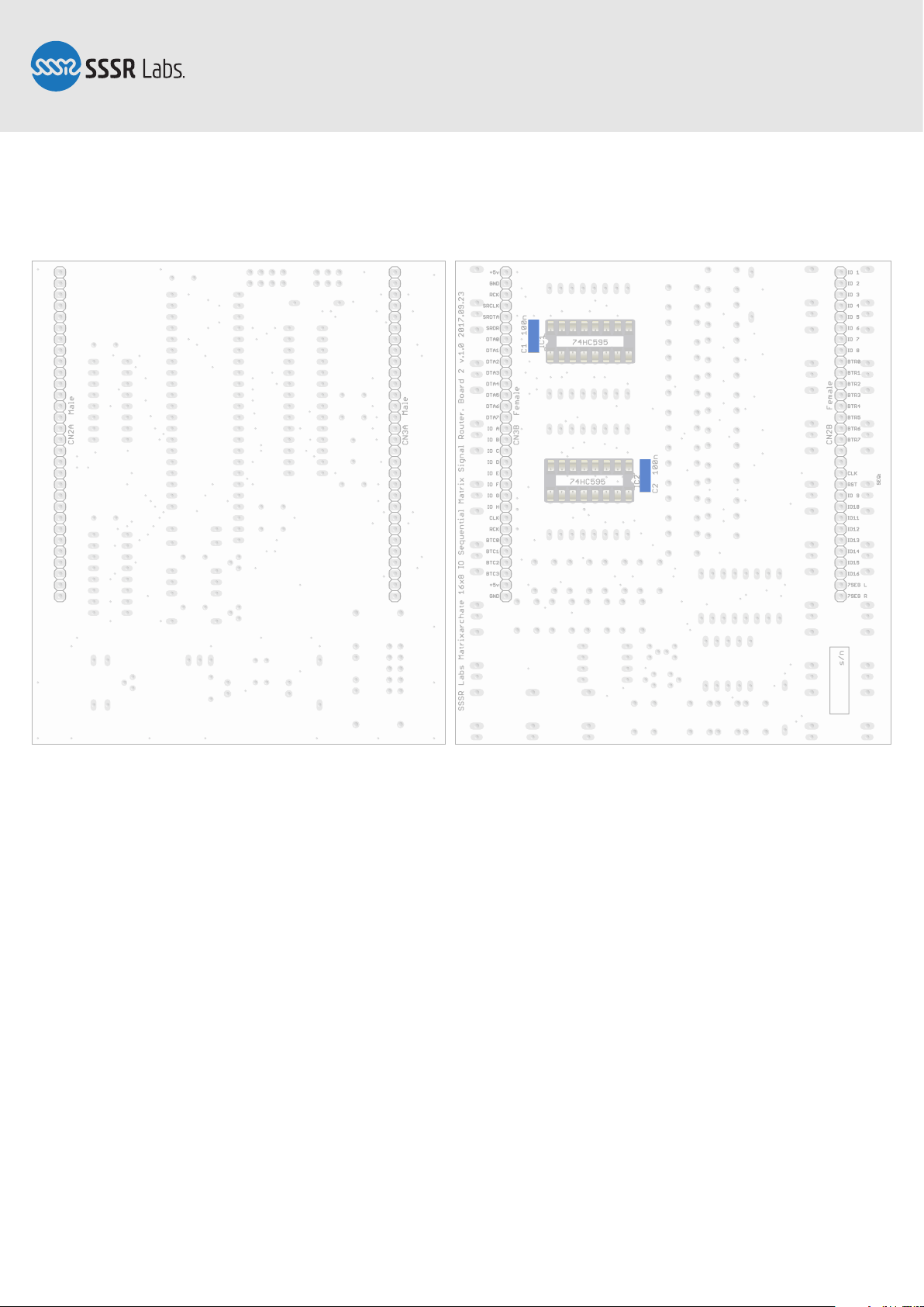
.1 uF
.1 uF
SM010, Assembly Manual
PCB Version 1.0
Step 3: Bypass capacitors
These two 100nF capacitors must also be placed on this side. These are not polarized
components labeled as “104”, “100n” or “.1µF”.
Page 4 of 22
Page 5
.1 uF
.1 uF
SM010, Assembly Manual
PCB Version 1.0
Step 4: 30-pin Headers
In order to align both boards perfectly, you need to solder all pin-headers at once when
they are in their working position. Connect each pair, then insert the male sides into
the Board 1, then carefully wear the Board 2 on the female sides to form a sandwich.
Then solder pins at each corner of each board to let headers keep this sandwich
together. After soldering the rest, you can disassemble the sandwich and continue to
the next step.
Page 5 of 22
Page 6
.1 uF
.1 uF
SN74HC595
SN74HC595
SM010, Assembly Manual
PCB Version 1.0
Step 5: ICs
Insert all chips into its sockets. Please pay attention to the orientation! All capacitors
are installed near the Pin 1
You’ve finished working with this side! It’s highly recommended to clean the top side of
this boards now, before installing the rest of components.
Page 6 of 22
Page 7
SM010, Assembly Manual
PCB Version 1.0
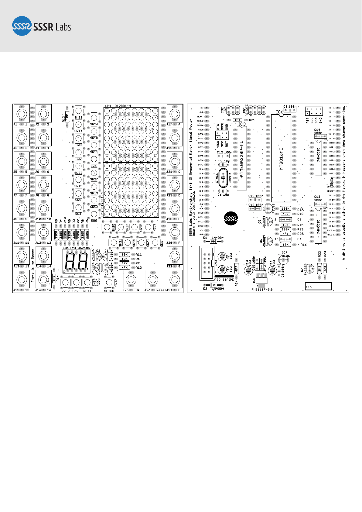
Step 6: Top Side of the PCB
The rest of the components will be installed on this side. Short instructions: please
assemble the module in the following order: Solder SMD voltage regulator, resistors,
diodes, quartz crystal, 18 pF capacitors, IC sockets, 1 nF capacitors, 100 nF capacitors,
all TO92 components (transistors, voltage regulators). Install and solder remaining
pin-headers, electrolytic capacitors, insert ICs, insert jack sockets, pushbuttons and
all displays, insert the windows (if needed), remove the rear protective film off the
windows, put the front panel on, and fasten few nuts by hand, solder everything but
displays, solder displays tightly pressing them to the windows, then put on the rest of
nuts, remove the front film, ..., PROFIT! If you need more details, the following pages
will guide you through this process more detailed.
Page 7 of 22
Page 8

SM010, Assembly Manual
PCB Version 1.0
Step 7: Voltage regulator
The AMS1117-5.0 is the only SMD component in our DIY kit.Place it accurately aligned
to its footprint, then solder just the pin 1. Adjust the orientation of the regulator with a
pair of tweezers, keeping the solder melted, then let it cool down and finally solder the
pin 3. Only after that, solder the pin 2 and the heatsink pin. This one will require long
heating up. Don’t worry about the overheating, this component is designed to be
heated seriously!
Page 8 of 22
Page 9

SM010, Assembly Manual
PCB Version 1.0
Step 8: Resistors
Install the resistors. You can use the above picture as the reference to verify values
before soldering.
Solder all resistors to the top side of the PCB, then proceed to step 9 and then flip the
PCB over, cut the leads and reflow and solder everything to the back side. This technique is the best method to accurately and firmly solder radial components, so it is
recommended to use with all components allowing you access to the top side.
Page 9 of 22
Page 10

SM010, Assembly Manual
PCB Version 1.0
Step 9: Protection Diodes
Solder two protection diodes. The 1n4004 may be substituted with any diode of the
40xx series: 1n4001–1n4007. Take care of the right orientation. (Refer to the picture)
It’s time to cut the leads and reflow installed components on the back side.
Page 10 of 22
Page 11

180
180
20.000
SM010, Assembly Manual
PCB Version 1.0
Step 10: The Crystal and 18p capacitors
Solder two 18 pF capacitors. Insert the crystal’s pins into the plastic spacer of the
similar shape and then solder them.
Page 11 of 22
Page 12

180
180
20.000
SM010, Assembly Manual
PCB Version 1.0
Step 11: IC Sockets
Insert all DIP IC sockets. Please pay double attention to the correct orientation. The
pin 1 of each chip on this side is directed up. Please refer to page 3 for best practice for
installing IC sockets.
Page 12 of 22
Page 13

180
180
20.000
1n
1n
SM010, Assembly Manual
PCB Version 1.0
Step 12: 1 nF Capacitors
Solder the 1 nF capacitors, which are labeled as “102” or “1n”.
Page 13 of 22
Page 14

180
180
20.000
1n
1n
.1 uF
.1 uF
.1 uF
.1 uF
.1 uF
.1 uF
.1 uF
.1 uF
.1 uF
SM010, Assembly Manual
PCB Version 1.0
Step 13: 100 nF Capacitors
Solder the 100 nF capacitors, which are labelled as “104” or “100n” or “0.1 µF”.
Page 14 of 22
Page 15

180
180
20.000
1n
1n
.1 uF
.1 uF
.1 uF
.1 uF
.1 uF
.1 uF
.1 uF
.1 uF
.1 uF
SM010, Assembly Manual
PCB Version 1.0
Step 14: Transistors and Voltage Regulators
There are two errors on the silkscreen of the PCB version 1.0.
1. IC9 (79L06) is shown contrariwise. You should place this regulator exactly as shown
in the picture.
2. IC7 (78L10) is labeled as 78L06. The correct IC is included to all kits.
Everything else is correct. Certain components in the TO92 package will need their
leads to be bent a little to better fit into their holes. Use sharp metal tweezers to do it.
Page 15 of 22
Page 16

180
180
20.000
1n
1n
.1 uF
.1 uF
.1 uF
.1 uF
.1 uF
.1 uF
.1 uF
.1 uF
.1 uF
SM010, Assembly Manual
PCB Version 1.0
Notch
Step 15: Power Header and Electrolytic Capacitors
Install the power pin-header. Notice the orientation! It’s recommended to solder two
pins in the opposite corners, then solder the rest of pins. The six central pins are connected to the ground plane and require extra heating. It is also recommended to plug
the Eurorack power cable to prevent pins from bending if the plastic case has started
melting due to extensive heating.
Install other pin-headers using a similar technique.
Solder the 10 µF electrolytic capacitors. They are polar components and must be oriented the right way according to the illustration. The blue or white stripe with the
Minus markings shows the negative pin, and the holes for the positive pins are marked
on the PCB with the Plus signs. Also, the positive lead is longer than negative.
Page 16 of 22
Page 17

180
180
20.000
1n
1n
.1 uF
.1 uF
.1 uF
.1 uF
.1 uF
.1 uF
.1 uF
.1 uF
.1 uF
SN74HC595
SN74HC595
SSSR Labs MCU Chip
MATRIXARCHATE 1.0
MT8816AE
SM010, Assembly Manual
PCB Version 1.0
Step 16: ICs
Insert all chips into its sockets. Please pay attention to the orientation. You can additionally clean the top sides of the PCB now, before installing the controls and the front
panel.
Page 17 of 22
Page 18

180
180
20.000
1n
1n
.1 uF
.1 uF
.1 uF
.1 uF
.1 uF
.1 uF
.1 uF
.1 uF
.1 uF
SN74HC595
SN74HC595
SSSR Labs MCU Chip
MATRIXARCHATE 1.0
MT8816AE
SM010, Assembly Manual
PCB Version 1.0
Step 17: Inserting Controls and LED Windows
Insert all jack sockets, all pushbuttons, and displays. The LED matrices have one side
labeled with the part number. This side must be oriented down as indicated by the
thick lines on footprints. The orientation and placement of other components are obvious. DO NOT solder anything before installing the front panel!
You need to insert plastic transparent windows into holes in the front panel if they are
not initially inserted. Some windows may have little barbs. You have to cut them out
with an Exacto knife. Also, the larger window may be a bit too tall for its hole. You’re
allowed to bend it and press to fit it into. Once the window has been inserted it will not
deform and will just fit very tightly. Don’t forget to remove the protective film on the
rear side of both windows!
Page 18 of 22
Page 19

MATRIXARCHATE SM010
16×8 IO SEQUENTIAL MATRIX SIGNAL ROUTER
1
2
3
4
5
6
7
8
9
10
11
12
13
14
15
16
A B C D E F G H
15
16
13 14
11 12
9 10
7 8
5 6
3 4
1 2
PREV SAVE SETUP/EXITNEXT
PROGRAM
STEP RESET
−10 REVERT CLEAR+10
[ LOCK ]
f2f1
SM010, Assembly Manual
PCB Version 1.0
Step 18: Soldering Controls
Put the front panel on the installed jacks. Fasten four nuts at the corners just to keep
the panel in its place. Pay attention to keep jack sockets being pressed tightly against
the PCB with no gaps! Solder all sockets.
Solder each pushbutton, two diagonally opposite pins at once, then correct their positions if needed, and solder the rest of pins.
You must tightly press LED displays against their windows and solder diagonally opposite leads of each component to the PCB. There will be a gap between the bottom of
the matrices and the surface of the PCB. It’s OK. Adjust the position if needed. Once
it's correct, solder the rest of leads.
Page 19 of 22
Page 20

MATRIXARCHATE SM010
16×8 IO SEQUENTIAL MATRIX SIGNAL ROUTER
1
2
3
4
5
6
7
8
9
10
11
12
13
14
15
16
A B C D E F G H
15
16
13 14
11 12
9 10
7 8
5 6
3 4
1 2
PREV SAVE SETUP/EXITNEXT
PROGRAM
STEP RESET
−10 REVERT CLEAR+10
[ LOCK ]
f2f1
SM010, Assembly Manual
PCB Version 1.0
Page 20 of 22
Step 19: Finishing the assembly
Clean the PCB if needed. Install and tighten the rest of nuts. Remove the protective
film from the front side of LED windows. Connect boards 1 and 2 together.
Page 21

MATRIXARCHATE SM010
16×8 IO SEQUENTIAL MATRIX SIGNAL ROUTER
1
2
3
4
5
6
7
8
9
10
11
12
13
14
15
16
A B C D E F G H
15
16
13 14
11 12
9 10
7 8
5 6
3 4
1 2
PREV SAVE SETUP/EXITNEXT
PROGRAM
STEP RESET
−10 REVERT CLEAR+10
[ LOCK ]
f2f1
SM010, Assembly Manual
PCB Version 1.0
Page 21 of 22
Step 20: ... PROFIT!
Congratulations! You’ve just assembled the Matrixarchate!
Page 22

MATRIXARCHATE SM010
16×8 IO SEQUENTIAL MATRIX SIGNAL ROUTER
1
2
3
4
5
6
7
8
9
10
11
12
13
14
15
16
A B C D E F G H
15
16
13 14
11 12
9 10
7 8
5 6
3 4
1 2
PREV SAVE SETUP/EXITNEXT
PROGRAM
STEP RESET
−10 REVERT CLEAR+10
[ LOCK ]
f2f1
SM010, Assembly Manual
PCB Version 1.0
Page 22 of 22
The Matrixarchate module does not require any adjustment since it’s completely digital
except for the analog switch IC. So, it is ready to be installed in your Eurorack system
or to be updated via ISP.
If everything is correct, after power-on it should display the program number and
some pattern on the LED matrix, depending on contents of the default firmware.
 Loading...