

S+S Regeltechnik HYGRASGARD RFTF-Modbus, HYGRASGARD RFTF-Modbus-P T 5L, HYGRASGARD RFTF-Modbus-PT D5 5L Operating Instructions, Mounting & Installation

D G F r
6000-3280-0000-1XX 328 00 -2 019 V 103 06 ⁄ 2019
HYGRASGARD
Bedienungs- und Montageanleitung
D
®
RFTF - Modbus
Raumbedien-Feuchte und -Temperaturfühler (± 2 %),
Aufputz, für Temperatur, relative / absolute Feuchte,
Taupunkt, Mischungsverhältnis, Enthalpie,
kalibrierfähig, mit
Operating Instructions, Mounting & Installation
G
Modbus
-Anschluss
Roomoperating humidity and temperaturesensor (± 2 %),
on-wall, for temperature, relative / absolute humidity,
dew point, mixture ratio, enthalpy,
calibratable, with
Notice d’instruction
F
Modbus
connection
Sonde d'humidité et de température ambiante (± 2 %),
en saillie, pour température, humidité relative et absolue,
point de rosée, rapport de mélange, enthalpie,
étalonnable, avec raccordement
Руководство по монтажу и обслуживанию
r
Modbus
Комнатный датчик влажности и температуры (± 2 %),
для открытого монтажа, для измерения температуры,
относительной ⁄ абсолютной влажности, точки росы,
соотношения компонентов смеси, энтальпии,
калибруемый, с подключением к шине
Modbus
S+S REGELTECHNIK GMBH
PIRNAER STRASSE 20
90411 NÜRNBERG ⁄ GERMANY
FON +49 (0) 911 ⁄ 5 19 47- 0
FAX +49 (0) 911 ⁄ 5 19 47-70
mail@SplusS.de
www.SplusS.de
Herzlichen Glückwunsch!
Sie haben ein deutsches Qualitätsprodukt erworben.
Congratulations!
You have bought a German quality product.
Félicitations !
Vous avez fait l’acquisition d’un produit allemand de qualité.
Примите наши поздравления !
Вы приобрели качественный продукт, изготовленный в Германии.

D G F r
HYGRASGARD
Maßzeichnung
Dimensional drawing
Plan coté
Габаритный чертеж
(Baldur 2)
®
RFTF - Modbus
34.6
32.6
RFTF - M odbus
98
TK: ø60
98
RFTF - M odbus - P T 5L
mit Display, Potentiome ter, Taster und LED-A nzeige
with display, potentiometer, push -but tons and LED display
avec écran, pot entio mètre, poussoir et affichag e LED
c дисплеем, потенциометром, кнопкой
и светодиодными индикаторами
RFTF - M odbus
mit Display
with display
avec écran
c дисплеем
2
mit Potentiometer, Taster, Drehschalter und LED-Anzeige
with potentiomet er, push-bu ttons, rota ry swi tches and LED display
avec po tentiomètre, pouss oir, commutateur rotatif et affichage LED
с потенциометром, кнопкой, поворотным выключателем
RFTF - M odbus - P T D5 5L
и светодиодными индикаторами

HYGRASGARD
3
4
5
1 2
r.H .
°C
offset
123456
ON DIPB
12345678
ON DIPA
°Cr.H .
+UB 24V AC/DC
–UB GND
Stecker
Display
RS485 Modbus A
RS485 Modbus B
Schirmung
Potentiometer
Präsenztaster
LED (interner Status)
DIP A: Busadresse
DIP B: Busparameter
(Baudrate, Parity ...)
Telegramm-Anzeige.
Empfang (LED grün)
Fehler (LED rot)
Stecker für Display
Kontaktseite:
rechts
Offset-Korrektur
Feuchte: ± 10% r.H.
Offset-Korrektur
Temperatur: ± 10°C
Drehschalter
D
Der kalibrierfähige Raumsensor
misst die relativen Feuchte und die Temperatur der Raum luft. Aus diesen Messgrößen werden intern verschieden Kenngrößen berechnet. Über den Modbus
können die folgenden Kenngrößen abgefragt werden: relative Feuchte [% r. H.], absolute Feuchte [g ⁄ m³], Mischungs verhältnis [g ⁄ kg], Taupunkt temperatur
[°C], Enthalpie [kJ ⁄ kg] (unter Vern achlässigung des atm. Luftdr uckes) und Raum temperatur [°C].
Hierbei ist wahlweise als Bedienelement ein Sollwert-Potentio meter, ein 5-poliger Drehschalter und ein Präsenztaster verfügbar. Für die Temperatur /
relative Feuchte / absolu te Feuchte / Taupunk t / Misc hungsv erhältnis / Enthalpie oder Sollw erta usgabe sind optional Ger äte mit LCD-A nzeige f ür die Mess wertdarstellung erhältlich. Über maximal 5 mehrfarbige LEDs können Betriebs zustände angezeigt werden. Die Ansteuerung der Anzeigen (LCDs), sowie
die Abf rage der Mess- und Bedienwert e erfolgt über die Bus-Schnit tstelle Modbus.
®
RFTF - Modbus
HYGRASGARD®
RFTF - M odbus
Rev. 2019 - V23
mit Modbus- Anschluss, wahlw eise mit ⁄ o hne Display im for mschönen Gehä use (Baldur 2)
TECHNISCHE DATEN
Spannungsversorg ung: 24 V AC (± 20 %) und 15…36 V DC
Leistungsaufnahm e: < 1 VA ⁄ 24 V DC; < 2,2 VA ⁄ 24 V AC
Sensor:
Datenpunkte: Temperatur, relative Feuchte, absolute Feuchte,
Messbereich: 0...100 % r.H. (Feuchte)
Abwei chung Feuchte: typisch
Abweichung Temperatur: typisch ± 0,2 K bei +25 °C
Nullpunkt-Offset: ± 10 % r.H. (Feuchte)
Umgebungstemperatur: Lag eru ng – 35...+8 5 °C;
Medium: saubere Luf t und
Busparameter:
ohne Bestromung
Bussch nitts telle: RS 485,
Busprotokoll: Modbus (RTU-Mode),
Baudrate: 9600, 19200, 38400 Baud
Statusanzeige: LED grün = Telegramm gültig
Signal filter ung: 4 s / 32 s
Gehäuse: Kunststoff, Werkstoff ABS,
Abmaß e: 98 x 98 x 3 3 mm (B aldur 2)
Montage: Wandmontage o der auf UP-Dose, Ø 55 mm, Unter teil mit
Langz eitst abilitä t: ± 1 % ⁄ Jah r
zulässige Luftfeuchte: < 95 % r. H., nicht k ondensierende Luft
Schut zklasse: III (nach EN 60 730)
Schut zart : IP 30 (n ach EN 6 0 529)
Normen: CE-Konformität nach EMV-Richtlinie 2 014 ⁄ 30 ⁄ EU,
Optional:
digitaler Feuchtesensor
mit integriertem Temperatursensor,
kleine Hysterese, hohe Langzeitstabilität
Taupunkt, Mischungsverhältnis, Enthalpie
sowie Sollwert-Potentiometer,
Drehschalter und Präsenztaster
0...+ 50 °C ( Temperat ur)
± 2,0 %
(20...80 % r. H.) bei +25 °C, sonst ± 3,0 %
± 10 °C (Temp eratur)
über Potentiometer einstellbar
Bet rie b 0...+50 °C
nicht aggressive
über DIP-Schalter
Busabschluss über DIP-Schalter aktivierbar.
Bis zu 32 Ge räte auf einem Segment möglich.
Bei größerer Anzahl von Geräten müssen
RS 485 -Transceiver eingesetzt werden.
Adr essber eich 0...
LEDs farblich programmierbar
, nicht br ennba re Gase
(im spannungslosem Zustand)
konfigurier- und adressierbar !
galvanisch getrennt,
247
einstellbar,
LED rot = Telegrammfehler
Farbe Reinweiß (ähnlich RAL 9010)
4-Loch, für Befestigung auf senkrecht oder waagerecht
installierten UP-Dosen für Kabeleinführung hinten, mit
Sollbruchst elle für K abeleinführung oben ⁄ u nten bei AP
nach EN 61 326
Display mit Beleuchtung,
Aussch nitt c a. 36 x 15 mm (B x H),
zur Anzeige der Ist-Feuchte und Ist-Temperatur oder
einer wählbaren Kenngröße oder
eines individuell programmierbaren Anzeigewertes
zweizeilig, programmierbar,
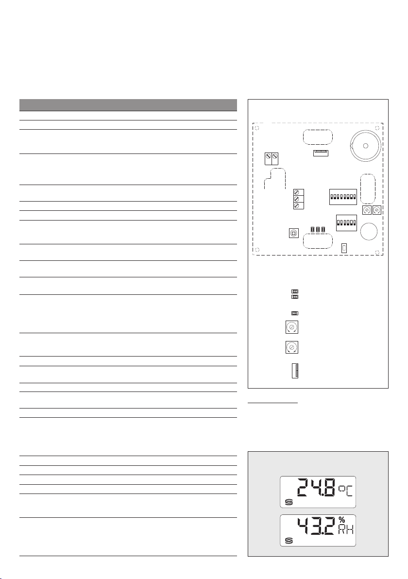
Schaltbild
DIP A: Busadresse
DIP B: Busparameter
(Baudrate, Parity ...)
Telegramm-Anzeige.
Empfang (LED grün)
Fehler (LED rot)
LED (interner Status)
Offset-Korrektur
Temperatur: ± 10°C
°C
Offset-Korrektur
Feuchte: ± 10% r.H.
r.H .
Stecker für Display
Kontaktseite:
rechts
RFTF- Modbus
Nullpunktkalibrierung
Die Fühler sind werkseitig eingestellt und abgeglichen.
Eine Justage ist über die beiden Offset-Potentio meter
möglich. Der Einstellber eich beträgt ca. ± 10 °C bzw.
± 10 % r.H.
Anzeige
Standard
RFTF - M odbus
Display
3
HYGRASGARD
D
®
RFTF - Modbus
Rev. 2019 - V23
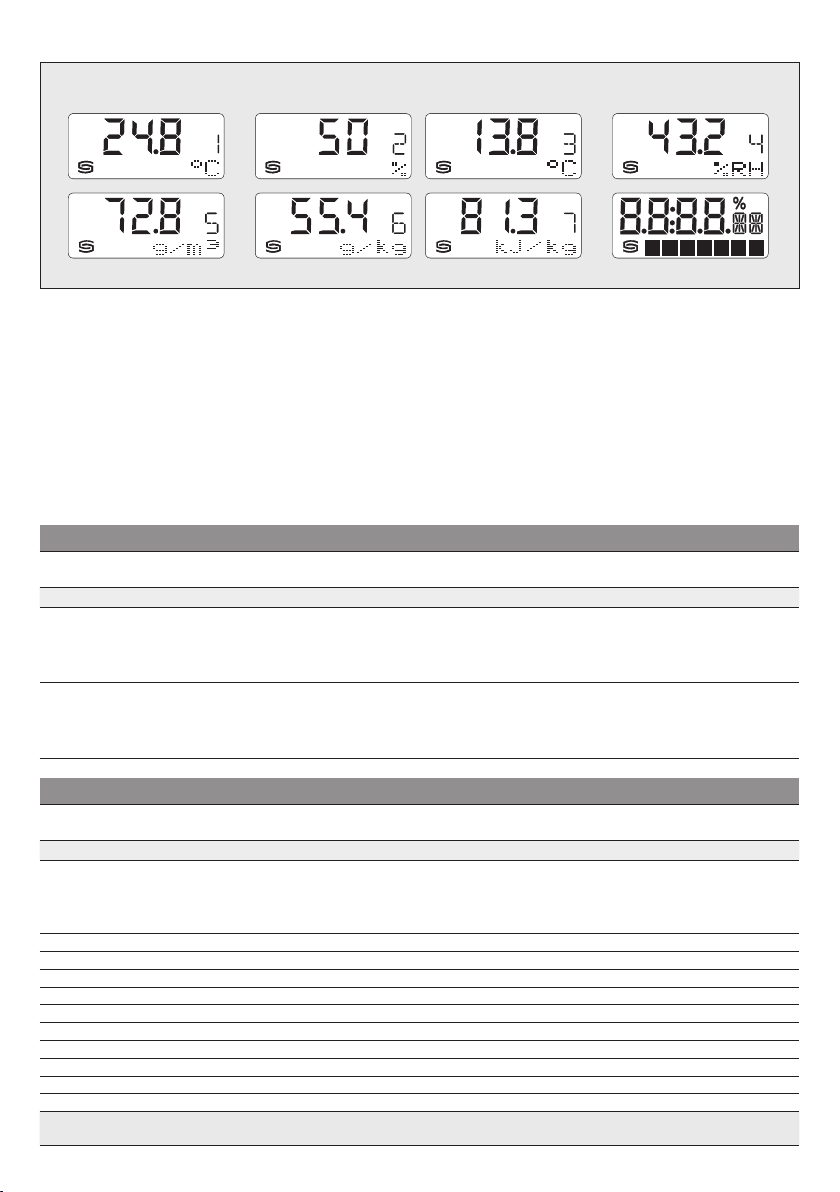
Anzeige
alternative Ausgangsgrößen
Standardmäßig werden in der ersten Zeile folgende
Mess werte mit den entsprechenden Einheiten
nacheinander angezeigt:
Temperatur
in °C,
relative Feuchte
Zur besseren Ablesbarkeit ist eine Hintergrund beleuchtung
vorha nden. Über die Modbusschnitts telle kann das Display
sowohl im 7- und 14-Segment-Bereich,
im Dot-Matrix-Bereich
individuell
programmiert werden.
HYGRASGARD® RFT F - Modbus
Typ ⁄ WG01 Messbereich ⁄ Anzeige
zyklisch
in % r.H.
als a uch
Raum-Feuchte und -Temperaturfü hler
Feuchte (umschaltbar) Temperatur
Über die Modbusschnittstelle kann anstelle
der Standard-Anzeige eine
Ausgangs größe
Hierbei wird in der ersten Zeile der Wert
mit Index und in der z weiten Zeile die
entsprechende Einheit
Der Index kennzeichnet den Anzeigetyp:
RFTF - Modbus
RFTF-MODBUS 0...100 % r. H. (default)
RFTF-MODBUS LCD
0...80 g ⁄ kg (MV )
3
0...80 g ⁄ m
0...85 kJ ⁄ kg (ENT.)
–20...+80 °C (T P)
0...100 % r. H. (default)
0...80 g ⁄ kg (MV )
0...80 g ⁄ m
0...85 kJ ⁄ kg (ENT.)
–20...+80 °C (T P)
(a .F. )
3
(a .F. )
Display
Index 1
Index 2
Index 3
Index 4
Index 5
Index 6
Index 7
Art.-Nr.
alternative
programmiert werden.
statisch
angezeigt.
Ausgang
0...+5 0 °C Modbus 1201-42B6-6000-000
0...+5 0 °C
Modbus ■ 1201-42B6-7000-000
RFTF - M odbus
Display
= Temperat ur in °C
= Sollwert-Poteniometer in
= Taupunkt in
= relative Feuchte in
= absolu te Feuchte in
= Mischungsver hältnis in
= Enthalpie in
°C
% r.H.
g ⁄ m³
kJ ⁄ kg
g ⁄ kg
%
HYGRASGARD® RFT F - Modbus
Typ ⁄ WG01 Messbereich ⁄ Anzeige
Raumbedien-Feuchte und -Temperaturfühler
Feuchte (umschaltbar) Temperatur
RFTF - Modbu s - xx
RFTF-MODBUS
RFTF-MODBUS
RFTF-MODBUS
RFTF-MODBUS
RFTF-MODBUS
RFTF-MODBUS
RFTF-MODBUS
RFTF-MODBUS
RFTF-MODBUS
RFTF-MODBUS
RFTF-MODBUS
Ausstattung: P
P
P
LCD (5 x wie o ben) (1 x wi e oben) Modbus ■ 1201-42B6-7001-005
P 5L
P 5L
LCD (5 x wie o ben) (1 x wi e oben) Modbus ■ 1201-42B6-7119-005
P D5
P D5 5L
P T D5 5L
P T
P T
LCD (5 x wie o ben) (1 x wi e oben) Modbus ■ 1201-42B6-7047-005
P T 5L
P T 5L
LCD (5 x wie ob en) (1 x wie oben) Modbus ■ 1201-42B6-7051-005
0...100 % r. H. (default)
0...80 g ⁄ kg (MV )
0...80 g ⁄ m
0...85 kJ ⁄ kg (ENT.)
–20...+80 °C (T P)
3
(a .F. )
(5 x wie o ben) (1 x wi e oben) Modbus 1201-42B6-6119-005
(5 x wie o ben) (1 x wi e oben) Modbus 1201-42B6-6012-841
(5 x wie o ben) (1 x wi e oben) Modbus 1201-42B6-6120-841
(5 x wie o ben) (1 x wi e oben) Modbus 1201-42B6-6121-841
(5 x wie o ben) (1 x wi e oben) Modbus 1201-42B6-6047-005
(5 x wie o ben) (1 x wi e oben) Modbus 1201-42B6-6051-005
= Potentiometer (Sollwertsteller)
T
= Präsenztaster
Ausgang
Display
Art.-Nr.
0...+5 0 °C Modbus 1201-42B6-6001-005
D5
= Drehschalter, 5-stufig
5L = LED-A nzeige, mehrf arbig (5x)
4

HYGRASGARD
1 2 3 4 5 6 7 8
ON DIP A
1 2 3 4 5 6
ON DIP B
D
®
RFTF - Modbus
| Konfiguration
BUSADRESSE
Busadresse
(binär codiert, Wertigkeit 1 bis 247 einstellbar)
DIP 1 DIP 2 DIP 3 DIP 4 DIP 5 DIP 6 DIP 7 DIP 8
128 64 32 16 8 4 2 1
O N O N
Beispiel zeigt 128 + 64 + 1 = 193 als Modbus -Adresse.
Die
Geräteadresse
Schalterst ellung Pos. 1 bis 8 – siehe Tabelle auf Rückseite!
Die Adresse 0 ist für Broadcast-Meldungen reserviert, die Adressen größer 247 dürfen nicht belegt werden
und werden vom Gerät ignoriert. Die DIP-Schalter sind binärcodiert mit folgender Wertigkeit:
DIP 1 =
128
DIP 2 =
64
DIP 3 = 32 ............ DIP 3 = OFF
DIP 4 = 16 ............ DIP 4 = OFF
DIP 5 = 8 ............ DIP 5 = OFF
DIP 6 = 4 ............ DIP 6 = OFF
DIP 7 = 2 ............ DIP 7 = OFF
DIP 8 =
OFF OFF OFF OFF OFF
im Bereich von
............ DIP 1 = ON
............ DIP 2 = ON
1
............ DIP 8 = ON folgt die Modbus-Adresse
1 bis 247
(Binärformat) wird über den DIP-Schalter [A] eingestellt.
O N
128 + 64 + 1 = 193
MODBUS
DIP-Schalter [A
BUSPARAMETER
Baudrate
(einstellbar)
9600 Baud
19200 Baud
38400 Baud
reserviert
DIP
DIP
1
O N
OFF
O N O N
O N
OFF
OFF OFF
2
MODBUS
DIP-Schalter [B
]
]
Parity
(einstellbar)
EV EN
(gerade)
ODD
(ungerade)
Die
Einstellbar sind
Die
Einstellbar sind
Die
Einstellbar ist Parity-Sicherung
Der 8N1-Modus wird über Pos. 5 des DIP-Schalters [B] aktiviert.
Die Funk tionalität der Pos. 3 (Parity) und Pos. 4 (Parity-Sicherung) des DIP-Schalters [B] wird somit deaktiver t.
Einstellbar ist 8N1 aktiv oder inaktiv (default) – siehe Tabelle !
Der
Einstellbar ist
Bei Änderung der Busparameter und Busadresse werden bei Geräten mit
im Display f ür ca. 30 S ekunden angezeigt.
KOMMUNIKATIONSANZEIGE
Die Kommunikation wird über 2 LED-Anzeigen signalisiert. Fehlerfrei empfangene Telgramme werden unabhängig von
der Geräteadresse durch Aufleuchten der grünen Anzeige signalisiert. Fehlerhafte Telegramme oder ausgelöste Modbus
Exception-Telegramme werden durch das Aufleuchten der roten Anzeige dargestellt.
DIAGNOSE
Fehlerdiagnosefunktion integriert
Parity-Sicherung
DIP
3
(ein/aus)
ak tiv
O N
(1 Stoppbit)
inaktiv (keine Parität)
OFF
(2 Stoppbits)
Baudrate
(Übertragungsgeschwindigkeit) wird über Pos. 1 und 2 des DIP-Schalters [B] eingestellt.
9600 Baud, 19200 Baud
Parity
wird über Pos. 3 des DIP-Schalters [B] eingestellt.
EVEN (gerade)
Parity-Sicherung
Busabschluss
aktiv
wird über Pos. 6 des DIP-Schalters [B] aktiviert.
oder
ODD (ungerade)
wird über Pos. 4 des DIP-Schalters [B] aktiviert.
(Busabschlusswiderstand von 120 Ohm) oder
aktiv (1 Stoppbit)
oder
38400 Baud
– siehe Tabelle !
oder
inaktiv (2 Stoppbits)
– siehe Tabelle !
8N1-M odus
DIP
4
(ein/aus)
O N
aktiv
OFF inak tiv
inaktiv
5
(default) OFF in ak ti v OFF
, d.h. keine Parity-Sicherung – siehe Tabelle !
(ohne Busabschluss) – siehe Tabelle !
Displayanzeige
DIP
O N
5
Busabschluss
(ein/aus)
aktiv
die entsprechenden Einstellungen
DIP
6
O N

HYGRASGARD
D
®
RFTF - Modbus
| Konfiguration
ANZEIGE IM DISPLAY
Standardmäßig werden in der ersten Zeile folgende Mess werte mit den entsprechenden Einheiten
Temperatur
Über die Modbusschnittstelle kann anstelle der Standard-Anzeige eine
Taupunkt
relative Feuchte
Hierbei wird in der ersten Zeile der Wert mit Index und in der zweit en Zeile die entsprechende Einheit
Der Index kennzeichnet den Anzeigetyp, z.B. Taupunkttemperatur (siehe Tabelle "Function 06 Write Single Register").
Über die Modbusschnittstelle kann die Display-Anzeige sowohl im 7- und 14-Segment-Bereich als auch im Dot-Matrix-Bereich
programmiert werden. Somit können auch beispielsweise Meldungen von der SPS angezeigt werden.
Für die
Die Register 4x0002 bis 4x0012 enthalten Informationen über die dar zustellenden Zeichen und Segmente.
Der Dot-Matrix-Ber eich ist ebenfalls in der Defaulteinstellung (Register 4x0001 enthält den Wert 0) programmierbar.
Im 7-Segment-Bereich wird dabei automatisch der aktuelle Messwert angezeigt.
Aufbau Segment-Muster (Register 4x0005)
Bit 0 ......
Bit 1 ......
Bit 2 ......
Bit 3 ......
Bit 4 ......
Bit 5 ......
Bit 6 ......
Bit 7 ......
Bit 8 ......
Bit 9 ......
Bit 10 ....
Bit 11 ....
Bit 12 ....
Bit 13 ....
Bit 14 ....
Bit 15 ....
Aufbau 14-Segment-Muster (Register 4x0003 und 4x0004)
Bit 0 ......
Bit 1 ......
Bit 2 ......
Bit 3 ......
Bit 4 ......
Bit 5 ......
Bit 6 ......
Bit 7 ......
Bit 8 ......
Bit 9 ......
Bit 10 ....
Bit 11 ....
Bit 12 ....
Bit 13 ....
Bit 14 ....
Bit 15 ....
in °C,
relative Feuchte
(in °C),
Mischungsverhältnis
(in %),
Temperatur
individuelle Anzeige
Dot A
Dot B
Dot C
Dot D
Dot DP
Prozent
- -
- -
- -
- -
- -
- -
- -
- -
- -
- -
A
B
C
D
E
F
G
G'
H
I
J
K
L
M
- -
- -
in % r.H. (Die Auflösung beträgt 1/10 °C bzw. 1/10 % r.H.)
(in g ⁄ kg),
(in °C) oder
Anzeigewert:
Index:
Einheit:
muss das Register 4x0001 (physikalischer Anzeigewert) den Wert 10 enthalten.
Dot A
Dot Matrix A B C D E F G
H
F B
G G'
E C
M
absolute Feuchte
Sollwert-Poteniometer
13.8
1
°C
Dot B Dot C Dot D Prozent
A
I
D
L
alternative Ausgangs größe
(in g ⁄ m3),
(in %)
Dot DP
J
K
Enthalpie
Beispiel für Zeichen
Grad Celsius (°C)
14-Segment 1:
227 57
(Register 4x003) (Register 4x004)
programmiert werden:
(in kJ ⁄ kg),
zyklisch
nacheinander angezeigt:
statisch
14-Segment 2:
angezeigt.
14-Segment 1
14-Segment 2
6
HYGRASGARD
D
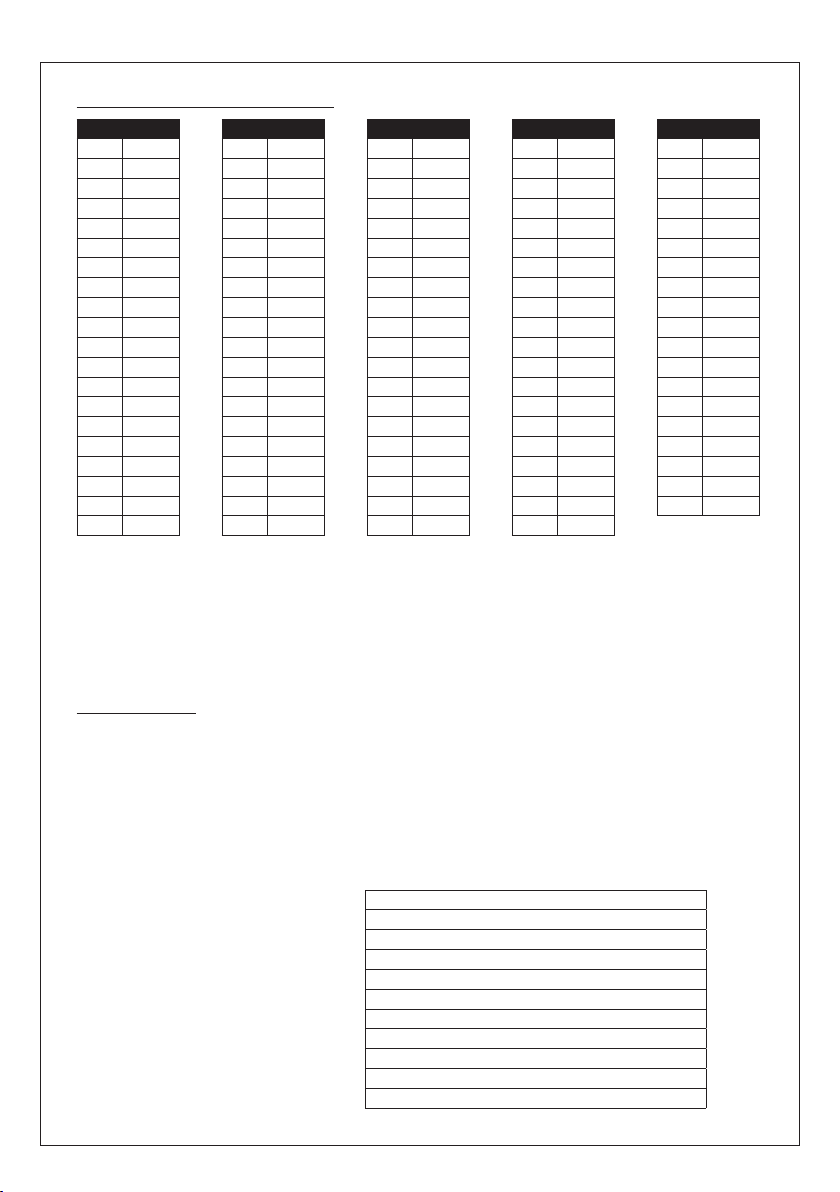
ASCII-Code-Tabelle für Dot Matrix Anzeigebereich
ASCII
32
33
34
35
36
37
38
40
41
42
43
44
45
46
47
48
49
50
51
52
Nicht in der Tabelle aufgeführte ASCII-Zeichen bzw. Steuerzeichen werden als Leerzeichen dargestellt.
®
RFTF - Modbus
Sign
Leer
!
“
#
$
%
&
(
)
*
+
,
-
.
/
0
1
2
3
4
ASCII
53
54
55
56
57
58
59
60
61
62
63
64
65
66
67
68
69
70
71
72
| Konfiguration
Sign
5
6
7
8
9
:
;
<
=
>
?
@
A
B
C
D
E
F
G
H
ASCII
73
74
75
76
77
78
79
80
81
82
83
84
85
86
87
88
89
90
91
93
Sign
I
J
K
L
M
N
O
P
Q
R
S
T
U
V
W
X
Y
Z
[
]
ASCII
100
101
102
103
104
105
106
107
108
109
110
111
112
113
Sign
94
^
95
_
96
\
97
a
98
b
99
c
d
e
f
g
h
i
j
k
l
m
n
o
p
q
ASCII
114
115
116
117
118
119
120
121
122
123
124
125
129
132
142
148
153
154
223
Sign
r
s
t
u
v
w
x
y
z
{
|
}
ü
ä
Ä
ö
Ö
Ü
°
LED-ANZEIGE
Einzelanzeige der LEDs (Register 4x0014 = 0)
Die LEDs können über Modbus einzeln in Farbe und Helligkeit angesteuert wer den.
Mit den Registern 4x0015 bis 4x0019 (LED x Mode, x=1…5) kann der jeweilige
(Dauerlicht/verschiedene Blinkarten) bzw. der Präsenztaster der LED zugeordnet werden.
Über die Register 4x0020 bis 4x0024 (LED x Farbe, x=1...5) kann die
(siehe Tabelle). Dabei st eht die Zehnerstelle für die Farbe, die Einerstelle für die Helligkeit. Der Wert 100 verweist bei
der Farb- und Helligkeitszuor dnung auf die entsprechenden Farbregister der LED (4x0025 bis 4x0039) mit der Möglichkeit
der einzelnen Zuordnung der drei Farben Rot, Grün und Blau.
Die LED-Anzeigen werden durch das MODBUS-Telegramm "
Die nebenstehende Registereinstellungen
entsprechen dem folgenden Beispiel
für verschiedene Betriebs-Störmeldungen:
LED 1 rot
Alarm – schnell blinkend
LED 2 gelb
LED 3 weiß
LED 4 grün
LED 5 weiß
Verknüpfung mit Taster
Warnung – langsam blinkend
Betrieb
Betrieb
Präsenz inklusive
Function 05 Write Single Coil
4x0014
= 0 (LEDs einzeln ansprechbar)
4x0015
= 4 (Blinken schnell)
4x0016
= 2 (Blinken mittel)
4x0017
= 0 (Dauerlicht)
4x0018
= 0 (Dauerlicht)
4x0019
= 5 (Zustandswechsel über Präsenztaster)
4x0020
= 35 Farbe Rot
4x0021
= 25 Farbe Gelb
4x0022
= 5 Farbe Weiß
4x0023
= 55 Farbe Grün
4x0024
= 5 Farbe Weiß
7
Anzeigezustand der LED
Farbe und Helligkeit der LED
" einzeln ein- und ausgeschaltet.
eingestellt werden
vorgegeben werden

HYGRASGARD
D
Bargraph-Anzeige der LEDs (Register 4x0014 = 1 bis 4)
Die LEDs sind in einer Anzeigekette verschaltet und zeigen den im Register 4x0013 (Bargraph Wert) eingetragenen Wert
farbig an. Einzelne Zwischenstufen werden über Helligkeitsänderungen dargestellt.
Die Farbauswahl des Bargraphs ist über das Register 4x0014 (Bargraph Mode) wählbar und kann gegebenenfalls über die
Farbregister der LED (4x0025 bis 4x0039) individuell eingestellt werden.
Die nebenstehende Registereinstellungen
entsprechen dem folgenden Beispiel
für eine
LED 1 rot (Farbregister)
LED 2 gelb
LED 3 gelbgrün
LED 4 grün
LED 5 grün
®
RFTF - Modbus
selbstdefinierte Ampelanzeige
| Konfiguration, Telegramme
4x0013
Anzeigewert
4x0014
:
= 4
4x0020
= 100 (selbst definierte Farbe Rot)
4x0021
= 25 Farbe Gelb
4x0022
= 45 Farbe Gelbgrün
4x0023
= 55 Farbe Grün
4x0024
= 55 Farbe Grün
4x0025
= 40 Farbregister Rot
4x0026
= 1 Farbregister Grün
4x0027
= 2 Farbregister Blau
POTENTIOMETER UND DREHSCHALTER
Die Potentiometerstellung wird im Bereich 0-100% erfasst und über das Register 3x0005 (Sollwert Potentiometer) ausgegeben.
Die Drehschalterstellung (optional) ist über das Register 3x0010 (Drehschalter) in den Stellungen 1 bis 5 abfragbar.
PRÄSENZTASTER
Der Präsenztaster ist über die Register 1x0001 bis 1x0003 abgebildet. Wird dem Taster keine LED zugeordnet
LED Mode ist ungleich Wert 5
(
1x0001 Taster gedrückt = 1, Erkennung über Flankenwechsel
1x0002 Taster freigegeben = 1, Erkennung über Flankenwechsel
1x0003 Tasterstatus, aktueller Tasterzustand zum Abfragezeitpunkt
Die Tasterinformationen, die durch Flankenwechsel ausgelöst werden, sind bis zur nächsten MODBUS-Telegrammabfrage
"
Function 02 Read Discrete Input
die Tasterbetätigung sicher erfasst werden kann.
Bei Zuordnung des Tasters zu einer LED (
LED-Zustandes. Die entsprechende LED muss über die Funktion 05 Write Single Coil eingeschaltet sein.
Die Abfrage des LED-Zustandes ist über das Register 1x0001 möglich.
Das Register 1x0002 ist ohne Funktion.
Das Register 1x0003 zeigt den aktuellen Tasterzustand zum A bfragezeit punkt an.
Der LED Zustand kann zusätzlich über die Funktion 05 Write Single Coil Bit 6 gesetzt bzw. gelöscht werden.
) so können die Tasterzustände über folgende Register erfasst werden:
" gespeichert, so dass auch bei längeren Bus-Abtastzyklen (z.B. 1 Sekunde)
LED Mode enthält Wert 5
) erfolgt automatisch bei jedem Tastendruck ein Wechsel des
TELEGRAMME
Function 04 Read Input Register
Register Parameter Data Typ e Value Range
3x0001
3x0002
3x0003
3x0004
3x0005
3x0006
3x0007
3x0008
3x0009
3x0010
Temperatur
Temperatur
Relative Feuchte
Relative Feuchte
Sollwert-Potentiometer Signed 16 Bit 0...1000 0.0...100.0 %
Taupunkt Berechneter Wert Signed 16 Bit 0...500 0.0...+50.0 °C
Absolute Feuchte Berechneter Wert Signed 16 Bit 0...800 0.0...80.0 g/m
Mischungsverhältnis Berechneter Wert Signed 16 Bit 0...800 0.0...80.0 g/kg
Enthalpie Berechneter Wert Signed 16 Bit 0...850 0.0...85.0 kJ/kg
Drehschalter Unsigned 8 Bit 0...4 Stellung 1...5
Abtastung 4 s
Filterung 32 s
Abtastung 4 s
Filterung 32 s
8
Signed 16 Bit 0...500 0.0...+50.0 °C
Signed 16 Bit 0...500 0.0...+50.0 °C
Signed 16 Bit 0...1000 0.0...100.0 % r.H.
Signed 16 Bit 0...1000 0.0...100.0 % r.H.
3

HYGRASGARD
D
®
RFTF - Modbus
| Telegramme
Function 06 Write Single Register & Function 16 Write Multiple Register
Register Parameter (Display) Data Ty pe Value Range
4x0001
4x0002
4x0003
4x0004
4x0005
4x0006
4x0007
4x0008
4x0009
4x0010
4x 00 11
4x0012
4x0040
physikalischer Anzeigewert Index im Display Unsigned 8 Bit 0...10 0...10
Standardanzeige (zyklisch):
Temperatur in °C,
relative Feuchte in % r.H.
alternative Anzeige (statisch):
Temperatur in °C 1 1
Sollwert-Potentiometer in % 2 2
Taupunkt in °C 3 3
Relative Feuchte in % r.H. 4 4
Absolute Feucht in g/m
Mischungsverhältnis in g/kg 6 6
Enthalpie in kJ/kg 7 7
frei konfigurierbare Anzeige – 10
7-Segment Wert Signed 16 Bit –999...9999 –999...9999
14-Segment Muster 1 siehe Grafik Unsigned 16 Bit siehe Bitmuster
14-Segment Muster 2 siehe Grafik Unsigned 16 Bit siehe Bitmuster
Segment Muster Unsigned 16 Bit siehe Bitmuster
Dot Matrix Zeichen A Unsigned 8 Bit 0...255 ASCII-Zeichen
Dot Matrix Zeichen B Unsigned 8 Bit 0...255 ASCII-Zeichen
Dot Matrix Zeichen C Unsigned 8 Bit 0...255 ASCII-Zeichen
Dot Matrix Zeichen D Unsigned 8 Bit 0...255 ASCII-Zeichen
Dot Matrix Zeichen E Unsigned 8 Bit 0...255 ASCII-Zeichen
Dot Matrix Zeichen F Unsigned 8 Bit 0...255 ASCII-Zeichen
Dot Matrix Zeichen G Unsigned 8 Bit 0...255 ASCII-Zeichen
Helligkeit LCD-Hintergrundbeleuchtung Unsigned 8 Bit 0...63 0...100%
3
– 0
5 5
Default-
einstellung
Register Parameter (LEDs) Data Ty pe Value Range
4x0013
4x0 014
4x0015
4x0016
4x0017
4x0018
4x0019
Bargraph Wert (LED) Unsigned 16 Bit 0...1000 0...1000
Bargraph Mode Unsigned 8 Bit 0...4
LEDs unabhängig ansteuerbar 0 Defaulteinstellung
Bargraph A Grün - Grün - Gelb - Gelb - Rot
Bargraph B Grün - Gelb - Rot
Bargraph C Blau - Rotblau - Rot
Bargraph D Farbe aus
LED 1 Mode Unsigned 8 Bit 0...5 Default = 0
LED 2 Mode Unsigned 8 Bit 0...5 Default = 0
LED 3 Mode Unsigned 8 Bit 0...5 Default = 0
LED 1 Mode Unsigned 8 Bit 0...5 Default = 0
LED 5 Mode Unsigned 8 Bit 0...5 Default = 0
Dauerlicht 0 Defaulteinstellung
Blinken kurz 1
Blinken mittel 2
Blinken lang 3
Blinken schnell 4
Wechsel mit Taster 5
(LED-Ampel)
(alle LEDs in gleicher Farbe)
(alle LEDs in gleicher Farbe)
LED-Farbregister
9
1
2
3
4

HYGRASGARD
D
®
RFTF - Modbus
| Telegramme
Function 06 Write Single Register & Function 16 Write Multiple Register
Register Parameter (LEDs) Data Ty pe Value Range
4x0020
4x0021
4x0022
4x0023
4x0024
4x0025
4x0026
4x0027
4x0028
4x0029
4x0030
4x0031
4x0032
4x0033
4x0034
4x0035
4x0036
4x0037
4x0038
4x0039
LED 1 Farbe Unsigned 8 Bit 0...100 Default = 0
LED 2 Farbe Unsigned 8 Bit 0...100 Default = 0
LED 3 Farbe Unsigned 8 Bit 0...100 Default = 0
LED 4 Farbe Unsigned 8 Bit 0...100 Default = 0
LED 5 Farbe Unsigned 8 Bit 0...100 Default = 0
Weiß 0...9
Gelb 10...19
Orange 20...29
Rot 30...39
Gelbgrün 40...49
Grün 50...59
Türkis 60...69
Blau 70...79
Violett 80...89
Farbregister
LED 1 Farbregister Rot 0...63
LED 1 Farbregister Grün 0...63
LED 1 Farbregister Blau 0...63
LED 2 Farbregister Rot 0...63
LED 2 Farbregister Grün 0...63
LED 2 Farbregister Blau 0...63
LED 3 Farbregister Rot 0...63
LED 3 Farbregister Grün 0...63
LED 3 Farbregister Blau 0...63
LED 4 Farbregister Rot 0...63
LED 4 Farbregister Grün 0...63
LED 4 Farbregister Blau 0...63
LED 5 Farbregister Rot 0...63
LED 5 Farbregister Grün 0...63
LED 5 Farbregister Blau 0...63
100
dunkel = 0
hell = 9
dunkel = 10
hell = 19
dunkel = 20
hell = 29
dunkel = 30
hell = 39
dunkel = 40
hell = 49
dunkel = 50
hell = 19
dunkel = 60
hell = 69
dunkel = 70
hell = 79
dunkel = 80
hell = 89
10

HYGRASGARD
D
®
RFTF - Modbus
| Telegramme
Function 05 Write Single Coil
Register Parameter Dat a Ty pe Value Range
0x0001
0x0002
0x0003
0x0004
0x0005
0x0006
0x0007
Multicolor LED 1 Bit 0 0 / 1 OFF - ON
Multicolor LED 2 Bit 1 0 / 1 OFF - ON
Multicolor LED 3 Bit 2 0 / 1 OFF - ON
Multicolor LED 5 Bit 3 0 / 1 OFF - ON
Multicolor LED 6 Bit 4 0 / 1 OFF - ON
Set / Clear
LED-Taster-Status
LCD-Hintergrundbeleuchtung Bit 6 0 / 1 OFF - ON
Bit 5 0 / 1 CLEAR - SET
Function 02 Read Discrete Input
Register Parameter Dat a Ty pe Value Range
1x0001
1x0002
1x0003
Hinweis: Die Adressen 1x0004...1x0008 werden mit dem Wert "0" gelesen.
Function 08 Diagnostics
Folgende
Sub Function
Code
00
01
04
10
11
12
13
14
15
Präsenztaster /
LED-Status
Präsenztaster freigegeben Bit 1 0 / 1 OFF - ON
Präsenztaster aktuell Bit 2 0 / 1 OFF - ON
Sub Function Codes
werden unterstützt
Parameter Data Ty pe Antwort
Echo der Sendedaten
(Loopback)
Neustart Modbus
(Reset Listen Only Mode)
Aktivierung Listen Only Mode Keine Antwort
Lösche Zähler Echo Telegramm
Zähler Bustelegramme Unsigned 16 Bit alle gültigen Bustelegramme
Zähler Kommunikationsfehler
(Parity, CRC, Framefehler, etc.)
Zähler Exception-Meldungen Unsigned 16 Bit Fehlerzähler
Zähler Slave-Telegramme Unsigned 16 Bit Slave-Telegramme
Zähler Telegramme ohne Antwort Unsigned 16 Bit Broadcastmeldungen (Adresse 0)
gedrückt /
gesetzt
Bit 0 0 / 1 OFF - ON
Echodaten
Echo Telegramm
Unsigned 16 Bit fehlerhafte Bustelegramme
Function 17 Report Slave ID
Aufbau Antworttelegramm
Byte Nr. Parameter Data Type Antwort
00
01
02
03
04
05
06
Byteanzahl Unsigned 8 Bit 6
Slave ID (Device Typ) Unsigned 8 Bit 11 =
Slave ID (Device Class) Unsigned 8 Bit 20 =
Statu s Unsigned 8 Bit 255 = RUN, 0 = STOP
Versionsnummer (Release) Unsigned 8 Bit 1...9
Versionsnummer (Version) Unsigned 8 Bit 1…99
Versionsnummer (Index) Unsigned 8 Bit 1
11
HYGRASGARD® MODBUS
HYGRASGARD® /
HYGRASREG
®

HYGRASGARD
D
Allgemeiner Aufbau Busstruktur
®
RFTF - Modbus
| Installation
MODBUS
RTU-Master
Passiver
Abzweig
LA LA
Leitungsabschluss
Stichleitung
(Drop-Kabel)
Slave 1 Slave 2
Bustopologie mit Abschluss- und Vorspannungswiderständen
Leitungsabschluss
Aktiver
Abzweig
MODBUS
RTU-Master
Stammleitung
(Trunk-Kabel)
Stichleitung:
kürzer 20m
A (D1) D+
B (D0) D–
RS-485
Slave n
Mehrfachabzweigung n:
kürzer 40m/n
5 V
Pull-Up- /
Vorspannungswiderstand
Pull-Down- /
Vorspannungswiderstand
Leitungsabschluss
Leitungsabschluss
Common
(GND)
Slave 1 Slave 2
Abschlusswiderstände dürfen nur an den Enden der Busleitung angebracht werden.
In Netzen ohne Repeater sind nicht mehr als 2 Leitungsabschlüsse erlaubt.
Über DIP 6 kann der Leitungsabschluss am Gerät aktiviert werden. Die Vorspannungswiderstände zur Buspegeldefinition
im Ruhezustand werden üblicherweise am Modbus-Master / Repeater aktiviert.
Die maximale Teilnehmerzahl pro Modbussegment beträgt 32 Geräte.
Bei größerer Teilnehmerzahl ist der Bus in mehrere über Repeater getrennte Segmente aufzuteilen.
Die Teilnehmeradresse kann von 1 bis 247 eingestellt werden.
Für die Busleitung ist ein Kabel mit paarverseilter Datenleitung / Spannungsversorgung und Kupferabschirmgeflecht
verwendet werden. Der Kapazitätsbelag der Leitung sollte dabei kleiner 100 pF/m betragen (z.B. Profibusleitung).
12

Montage und Inbetriebnahme
D
Die Geräte sind im spannungslosen Zustand anzuschließen. Der Anschluss
der Geräte darf nur an Sicherheitskleinspannung er folgen. Folgeschäden,
welche durch Fehler an diesem Gerät entstehen, sind von der Gewährleistung und Haf tung ausgeschlossen. Montage und Inbetriebnahme der
Geräte darf nur durch autorisiertes Fach personal erfolgen. Es gelten
ausschließlich die technischen Daten und Anschluss be dingungen der zum
Gerät gelieferten Geräte etikettdaten, der Mon tage- und Bedienungsan
leitung. Abweichungen zur Katalog dar stellung sind nicht zusätzlich aufgeführt und im Sinne des technischen Fortschritts und der stetigen
Verbesserung unserer Produkte möglich. Bei Veränderungen der Geräte
durch den Anwender entfallen alle Gewährleistungs an sprüche. Der Betrieb
in der Nähe von Geräten, welche nicht den EMV-Richtlinien entsprechen,
kann zur Beeinflussung der Funktionsweise führen. Dieses Gerät darf
nicht für Überwachungszwecke, welche dem Schutz von Personen gegen
Gefährdung oder Verle tzung dienen und nicht als NOT-AUS-Schalter an
Anlagen und Maschinen oder vergleichbare sicherheitsrelevante Aufgaben
verwendet werden.
Die Gehäuse- und Gehäusezubehörmaße können geringe Toleranzen zu
den Angaben dieser Anleitung aufweisen.
Veränderungen dieser Unterlagen sind nicht gestattet.
Bei Reklamationen werden nur vollständige Geräte in Original ver packung
angenommen.
Wichtige Hinweise
D
Als AGB gelten ausschließlich unsere sowie die gültigen „Allgemeinen Lieferbedingungen für Erzeugnisse und Leistungen der Elektro industrie“
(ZVEI Bedingungen) zuzüglich der Ergänzungsklausel „Erweiterter Eigentumsvorbehalt“.
Außerdem sind folgende Punkte zu beachten:
– Vor der Installation und Inbetriebnahme ist diese A nleitung zu lesen und die alle darin gemachten Hinweise sind zu beachten!
– Der Anschluss der Gerät e darf nur an Sicherheit skleinspannung und im spannungslosen Zustand erfolgen.
Um Schäden und Fehler am Gerät (z.B. durch Spannungsinduktion) zu verhindern, sind abgeschirmte Leitungen zu verwenden,
eine Parallelverlegung zu stromführenden Leitungen zu vermeiden und die EM V- Richtlinien zu beachten.
– Dieses Gerät ist nur für den angegebenen Verwendungszweck zu nutzen, dabei sind die entsprechenden Sicherheitsvorschrif ten des VDE,
der Länder, ihrer Überwachungsorgane, des TÜV und der örtlichen EVU zu beachten.
Der Käu fer hat die Einhaltung der Bau- und Sicherungsbestimmung zu gewährleis ten und Gefährdungen aller Ar t zu ver meiden.
– Für Mängel und Schäden, die durch unsachgemäße Verwendung dieses Gerätes entstehen,
werden keinerlei Gewährleistungen und Haftungen übernommen.
– Folgeschäden, welche durch Fehler an diesem Gerät entstehen, sind von der Gewährleistung und Haftung ausgeschlossen.
– Montage und Inbetriebnahme der Geräte darf nur durch Fachpersonal erfolgen.
– Es gelten ausschließlich die technischen Daten und Anschlussbedingungen der zum Gerät gelieferten Montage- und Bedienungs anleitung,
Abweichungen zur Katalogdarstellung sind nicht zusätzlich aufgeführt und im Sinne des technischen For tschritts und der stetigen Verbesserung
unserer Produkte möglich.
– Bei Veränderungen der Geräte durch den Anwender entfallen alle Gewährleistungsansprüche.
– Dieses Gerät dar f nicht in der Nähe von Wärmequellen ( z.B. Heizk örpern) oder deren Wär mestrom eingesetz t werden,
eine direkte Sonnen einstrahlung oder Wärmeeinstrahlung durch ähnliche Quellen (starke Leuchte, Halogenstrahler) ist unbedingt zu vermeiden.
– Der Betrieb in der Nähe von Geräten, welche nicht den EMV- Rich tlinien entspr echen, k ann zur B eeinflussung der Funk tionsweise führen.
– Dieses Gerät dar f nicht f ür Über wachungszwecke, welche dem Schut z von Personen gegen Gefährdung oder Verletzung dienen
und nicht als Not-Aus-Schalter an Anlagen und Maschinen oder vergleichbare sicherheitsrelevante Aufgaben verwendet werden.
– Die Gehäuse- und Gehäusezubehörmaße können geringe Toleranzen zu den Angaben dieser Anleitung aufweisen.
– Veränderungen dieser Unterlagen sind nicht gestattet.
– Reklamationen werden nur vollständig in Originalverpackung angenommen.
Eine Inbetriebnahme ist zwingend durchzuführen und darf nur von Fachpersonal vorgenommen werden!
Vor der Montage und Inbetriebnahme ist diese Anleitung zu lesen und die alle darin gemacht en Hinweise sind zu beachten!
Hinweise zum mechanischen Ein- und Anbau:
Der Einbau hat unter Berücksichtigung der einschlägigen, für den Messort
gültigen Vorschriften und S tandards (wie z. B. Schweiß vor schriften usw.)
zu erfolgen. Insbesondere sind zu berücksichtigen:
– VDE ⁄ VDI Technische Temperatur messungen, Richtlinie,
Mess an ordnungen für Temperaturmessungen
– die EMV-Richtlinien, diese sind einzuhalten
– eine Parallelverlegung mit stromführenden Leitungen ist
unbedingt zu vermeiden
– es wird empfohlen abgeschirmte Leitungen zu verwenden,
dabei ist der Schirm einseitig an der DDC ⁄ SPS aufzulegen.
Der Einbau hat unter Beachtung der Übereinstimmung der vor liegenden
technischen Parameter der Thermometer mit den realen Einsatzbedingungen zu erfolgen, insbesondere:
– Messbereich
– zulässiger maximaler Druck, Strömungsgeschwindigkeit
– Einbaulänge, Rohrmaße
– Schwingungen, Vibrationen, St öße sind z u vermeiden (< 0,5 g)
Hinweise zur Inbetriebnahme:
Dieses Gerät wurde unter genormten Bedingungen kalibriert, abgeglichen
und geprüft. Bei Betrieb unter abweichenden Bedingungen empfehlen wir
Vorort eine manuelle Justage erstmals bei Inbetriebnahme sowie
anschließend in regelmäßigen Abständen vorzunehmen.
13
HYGRASGARD
3
4
5
1 2
r.H .
°C
offset
123456
ON DIPB
12345678
ON DIPA
°Cr.H .
Plug for
display
+UB 24V AC/DC
–UB GND
RS485 Modbus A
RS485 Modbus B
Shielding
Potentiometer
Presence
button
Plug for display
contact is
on the right side
DIP A: Bus address
DIP B: Bus parameters
(Baud rate, parity ...)
Telegram indicator
Reception (LED green)
Error (LED red)
LED (internal status)
Offset correction
temperature: ± 10°C
Offset correction
humidit y: ± 10% r.H.
Turn switch
G
The calibratable room sensor
measur es the relativ e hu midity and temperat ure of the room air. These measurands are used to internally
used to r etrie ve the following parameters: relative humidity [% r. H.], absolute humidity [g ⁄ m³], mixture ratio [g ⁄ kg], dew point temperature [°C], enthalpy
[kJ ⁄ kg] (ignoring atmospheric air pressure) and room temperature [°C]. As operating element you ca n chooc e betw een a pot entiometer, a 5-p ole rot ary
switch or a presence bu tton. For the t emper ature / r elati ve humidity / abs olute humidit y / dew poin t / mixture rat io / enthalpy or setpoint o utput devices with
LCD display are op tionally available for displaying readings. Oper ating status can be displayed via a
(LCDs), as well as the retrieval of measure ment and control values, are controlled via the Modbus inter face.
®
RFTF - Mo dbus
HYGRASGARD®
RFTF - M odbus
with Modbus connection, with/without
Rev. 2019 - V23
optional display in an elega nt housing (Baldur 2)
calculate var ious parameters. The Modbus c an be
maximum of 5 mult i-coloured L EDs. These displays
TECHNICAL DATA
Power s upply: 24 V AC (± 20 %) and 15…36 V DC
Power c onsumption: < 1 VA ⁄ 24 V DC; < 2.2 VA ⁄ 24 V AC
Sensor:
Data points: Temperatu re, rela tive humidity, absolut e humidi ty,
Measur ing rang e: 0...100 % r.H. (humidity)
Deviation, humidity: t ypically
Temperat ure deviatio n: typic ally ± 0.2 K a t +25 °C
Zero point of fset: ± 10 % r.H. (humidi ty)
Ambient temperature: Stor age –35...+ 85 °C;
Medium: clean air and
Bus parameters:
Bus in terfa ce: R S 485,
Bus pr oto col: Modbus ( RTU mo de),
Baud ra te: 9600, 1920 0, 38400 Baud
Stat us indicator: LED green = Telegra m valid
Signal filtering: 4 s / 32 s
Housing: plastic, mate rial AB S,
Dimensi ons: 98 x 98 x 3 3 mm (Ba ldur 2)
Installation: wall mounting or on in- wall flush box, Ø 5 5 m m,
Long- term s tabilit y: ± 1 % ⁄ year
Permissible air humidit y: < 95 % r. H., non-p recipi tating air
Prot ectio n class: III (acc ording to EN 60 730)
Prot ectio n type: IP 30 (acc ording to EN 60 529)
Standards: CE conformity
Features:
Digital humidity sensor
with integrated temperature sensor,
low hysteresis, high long-ter m stability
dew poin t, mixt ure ra tio, ent halpy
and setpoint potentiometer,
rotary switch and p resence button
0...+ 50 °C (tem peratu re)
± 2.0 %
(20...80 % r. H.) at +25 °C, otherwise ± 3.0 %
± 10 °C (te mperat ure)
adjustable using potentiometer
Operation 0...+50 °C
other
non-aggressive
In the absence of current delivery
can be
configured and addressed v ia DIP switch!
galvanically isolated,
bus ter mination can be a ctivated via DIP swit ch.
Up to 32 de vices possible in o ne segment.
In case of a g reat er number of devices,
RS 485 transceivers mus t be used.
address ran ge 0...
LEDs colour-programmable
, non-combustible gases
247
selectable,
LED red = Telegram err or
colour pure white (similar to RA L 9010)
base with 4 holes, f or att achment to vertically or
horizontall y installed in-wall flus h boxes for rear cable ent ry,
with predetermined breaking point for cable entry
from t op ⁄ bott om in case of plain on -wall installation
accor ding to EMC Direc tive 2014 ⁄ 30 ⁄ EU,
accor ding to EN 61 326
Display with illumination,
cuto ut appr ox. 36 x 15 mm (B x H),
to displa y actual humidity and temperature
or a selectable parameter
or an individually programmable display value
two-line, programmable,
(under currentless conditions)
14
Schematic diag ram
°C
r.H .
DIP A: Bus address
DIP B: Bus parameters
(Baud rate, parity ...)
Telegram indicator
Reception (LED green)
Error (LED red)
LED (internal status)
Offset correction
temperature: ± 10°C
Offset correction
humidit y: ± 10% r.H.
Plug for display
contact is
on the right side
RFTF- Modbus
Zero point calibration
The sensors ar e prese t and calibrated at the f actory.
Adjust ment is possible using the t wo offset potentiometers.
Range of a djustment: approx. ± 10 °C or ± 10 % r.H.
Display
standard
RFTF - M odbus
Display

HYGRASGARD
G
®
RFTF - Mo dbus
Rev. 2019 - V23
Display
alternative output variables
By default, the first lines indicate the following measurements
with the corr esponding unit s
temperature
Backlighting is provided for improved legibility. The Modbus
inter face allows the display t o be
both in t he 7 and 14 segment range an d in the dot-mat rix
range.
in °C,
HYGRASGARD® RFT F - Modbus
Type ⁄ WG01 Measuring Range ⁄ Readout
cyclically
relative humidity
and consecutively:
in % r.H.
individually
configured,
Room humidity and temperature sensor
Humidity (switchable) Temperature
The Modbus int erface can be used to pr ogram
an
alternative output variable
sta nda rd d ispl ay.
In this case, the first line indicat es the value
and index while th e second line indicates t he
corresponding unit
The index ident ifies the display type:
RFTF - Modbus
RFTF-MODBUS 0...100 % r. H. (default)
RFTF-MODBUS LCD
0...80 g ⁄ kg (MR)
3
0...80 g ⁄ m
0...85 kJ ⁄ kg (ENT.)
–20...+80 °C (DP )
0...100 % r. H. (default)
0...80 g ⁄ kg (MR)
0...80 g ⁄ m
0...85 kJ ⁄ kg (ENT.)
–20...+80 °C (DP )
(A.H.)
3
(A.H.)
RFTF - M odbus
Index 1
= temperature in °C
Index 2
= setpoint pot entiometer in
Index 3
= dew poin t in
Index 4
= relative humidity in
Index 5
= absolu te humidity in
Index 6
= mixture rat io in
Index 7
= enthalpy in
Item No.
°C
kJ ⁄ kg
statically
instead of t he
.
Output
Display
0...+5 0 °C Modbus 1201-42B6-6000-000
0...+5 0 °C
Modbus ■ 1201-42B6-7000-000
g ⁄ kg
Display
% r.H.
g ⁄ m³
%
HYGRASGARD® RFT F - Modbus
Type ⁄ WG01 Measuring Range ⁄ Readout
Roomoperating humidity and temperature sensor
Humidity (switchable) Temperature
RFTF - Modbu s - xx
RFTF-MODBUS
RFTF-MODBUS
RFTF-MODBUS
RFTF-MODBUS
RFTF-MODBUS
RFTF-MODBUS
RFTF-MODBUS
RFTF-MODBUS
RFTF-MODBUS
RFTF-MODBUS
RFTF-MODBUS
Equipment: P
P
P
LCD (5 x as ab ove) (1 x as abo ve) Modbus ■ 1201-42B6-7001-005
P 5L
P 5L
LCD (5 x as ab ove) (1 x as abo ve) Modbus ■ 1201-42B6-7119-005
P D5
P D5 5L
P T D5 5L
P T
P T
LCD (5 x as ab ove) (1 x as abo ve) Modbus ■ 1201-42B6-7047-005
P T 5L
P T 5L
LCD (5 x as abo ve) (1 x as abov e) Modbus ■ 1201-42B6-7051-005
0...100 % r. H. (default)
0...80 g ⁄ kg (MR)
0...80 g ⁄ m
0...85 kJ ⁄ kg (ENT.)
–20...+80 °C (DP )
3
(A.H.)
(5 x as ab ove) (1 x as abo ve) Modbus 1201-42B6-6119-005
(5 x as ab ove) (1 x as abo ve) Modbus 1201-42B6-6012-841
(5 x as ab ove) (1 x as abo ve) Modbus 1201-42B6-6120-841
(5 x as ab ove) (1 x as abo ve) Modbus 1201-42B6-6121-841
(5 x as ab ove) (1 x as abo ve) Modbus 1201-42B6-6047-005
(5 x as ab ove) (1 x as abo ve) Modbus 1201-42B6-6051-005
= Potentiometer (setpoint setter)
T
= Presence push-but tons
Output
Display
Item No.
0...+5 0 °C Modbus 1201-42B6-6001-005
D5
= Rotar y swit ch, 5-step
5L = LED display, multi- colour (5x)
15

HYGRASGARD
1 2 3 4 5 6 7 8
ON DIP A
1 2 3 4 5 6
ON DIP B
G
®
RFTF - Mo dbus
| Configuration
BUS ADDRESS
Bus addr ess
(binar y coded, value selectable from 1 to 247)
DIP 1 DIP 2 DIP 3 DIP 4 DIP 5 DIP 6 DIP 7 DIP 8
128 64 32 16 8 4 2 1
O N O N
Example shows 128 + 64 + 1 = 193 as Modbus address.
The
device address
For switch positions 1 t o 8 see the table on the back!
Address 0 is reserved for broadcast messages. Addresses greater than 247 must not be assigned
and are ignored by the device. The DIP swit ches ar e binary-coded with the following values:
128
DIP 1 =
64
DIP 2 =
DIP 3 = 32 ............ DIP 3 = OFF
DIP 4 = 16 ............ DIP 4 = OFF
DIP 5 = 8 ............ DIP 5 = OFF
DIP 6 = 4 ............ DIP 6 = OFF
DIP 7 = 2 ............ DIP 7 = OFF
DIP 8 =
OFF OFF OFF OFF OFF
in the range of
............ DIP 1 = ON
............ DIP 2 = ON
1
............ DIP 8 = ON The switch positions shown here results in the Modbus address
1 to 247
is set at DIP switch [A].
O N
DIP switch [A
BUS PARAMETERS
Baud rate
(selectable)
9600 baud
19200 baud
38400 baud
Reserved
DIP 1 DIP
O N
OFF
O N O N
O N
OFF
OFF OFF
2
MODBUS
DIP switch [B]
MODBUS
]
128 + 64 + 1 = 193
Parity
(selectable)
EVEN
(numbered)
ODD
(numbered)
The
Selectable are
Parity
Selectable are EVEN or
Parity check
Selectable are
The 8N1 mode is activated via DIP switch 5 of DIP switch block [B].
The functionality of DIP switch 3 (parit y) and DIP switch 4 (parity check) of DIP switch block [B] is ther efore deactivated.
Select able are 8N1 active or inactive (default) – see table !.
Bus termination
Selectable are
When bus parameters and bus address are changed at devices with
the respective settings are shown on the display for approx. 30 seconds.
COMMUNICATION INDICATOR
Communication is indicated via two LEDs. Error-fr ee received telegrams are signalized by t he green LED lighting up, regardless of
the device addr ess. Faulty telegrams or triggered Modbus exception telegrams are depicted by the red LED lighting up.
DIAGNOSTICS
An error diagnostic function is integrated
Parity check
DIP
3
(on / off)
Active
O N
(1 stop bit)
Inactive (no parity)
OFF
(2 stop bits)
baud rate
(speed of transmission) is set at DIP switches 1 and 2 of DIP switch block [B].
9600 baud, 19200 baud
is set at DIP switch 3 of DIP switch block [B].
is activated via DIP switch 4 of DIP switch block [B].
ODD
– see table!
active (1 stop bit)
is activated via DIP switch 6 of DIP switch block [B].
active
(bus termination resistance of 120 Ohm), or inactive (no bus termination) – see table!
, or
, or
38400 baud
inactive (2 stop bits)
DIP
4
O N
OFF Inactive (default) OFF I naktive OFF
– see table!
, i.e. no parit y check – see table!
display
16
8N1-M odus
(on / off)
Active
,
DIP
O N
5
Bus termination
(on / off)
Aktive
DIP
6
O N

HYGRASGARD
G
®
RFTF - Mo dbus
| Configuration
READOUT IN THE DISPLAY
By default, the first lines indicate the following measurements with the corresponding units
temperature
The Modbus interface can be used to program
dew point
relative humidity
In this case, the first line indicates the value and indexwhile the second line indicates the corresponding unit
The index indicates the display type, e.g. dew-point t emperature (see the table "Function 06 Write Single Register").
The Modbus interface allows the display screen to be individually conf igured, both in the 7 and 14 segment range and in
the dot-matrix range. This means that messages such as those from the PLC can be displayed.
For the
The registers 4x0002 to 4x0012 contain information about the characters and segments to be displayed.
The dot-matrix area is also programmable in the default setting (register 4x0001 contains the value 0).
In this case, the current measured value is automatically displayed in the 7-segment ar ea.
Composition of Segment Pattern (Register 4x0005)
Bit 0 ......
Bit 1 ......
Bit 2 ......
Bit 3 ......
Bit 4 ......
Bit 5 ......
Bit 6 ......
Bit 7 ......
Bit 8 ......
Bit 9 ......
Bit 10 ....
Bit 11 ....
Bit 12 ....
Bit 13 ....
Bit 14 ....
Bit 15 ....
Composition of 14-Segment Pattern (Register 4x0003 and 4x0004)
Bit 0 ......
Bit 1 ......
Bit 2 ......
Bit 3 ......
Bit 4 ......
Bit 5 ......
Bit 6 ......
Bit 7 ......
Bit 8 ......
Bit 9 ......
Bit 10 ....
Bit 11 ....
Bit 12 ....
Bit 13 ....
Bit 14 ....
Bit 15 ....
in °C,
relative humidity
(in °C),
mixture ratio
(in %),
individual display
Dot A
Dot B
Dot C
Dot D
Dot DP
Percent
- -
- -
- -
- -
- -
- -
- -
- -
- -
- -
A
B
C
D
E
F
G
G'
H
I
J
K
L
M
- -
- -
in % r.H. (Resolution: 1/10 °C or 1/10 % r.H.)
(in g ⁄ kg),
temperature
Reading:
Index:
Unit:
, the register 4x0001 (physical value displayed) must contain the value 10.
Dot A
Dot Matrix A B C D E F G
H
F B
G G'
E C
M
an alternative output variable
absolute humidity
(in °C) or
setpoint potentiometer
13.8
1
°C
Dot B Dot C Dot D Percent
A
D
(in g ⁄ m3),
Dot DP
I
L
instead of the standard display:
enthalpy
(in kJ ⁄ kg),
(in %)
J
K
cyclically
and consecutively:
Example for characters
Degrees Celsius (°C)
14-Segment 1:
227 57
(Register 4x003) (Register 4x004)
statically
14-Segment 1
14-Segment 2
14-Segment 2:
.
17

HYGRASGARD
G
ASCII Code Table for Dot Matrix Display Area
ASCII
32
33
34
35
36
37
38
40
41
42
43
44
45
46
47
48
49
50
51
52
ASCII characters or control characters are displayed as spaces.
®
Sign
Blank
!
“
#
$
%
&
(
)
*
+
,
-
.
/
0
1
2
3
4
RFTF - Modbus
ASCII
53
54
55
56
57
58
59
60
61
62
63
64
65
66
67
68
69
70
71
72
| Configuration, Telegrams
Sign
5
6
7
8
9
:
;
<
=
>
?
@
A
B
C
D
E
F
G
H
ASCII
73
74
75
76
77
78
79
80
81
82
83
84
85
86
87
88
89
90
91
93
Sign
I
J
K
L
M
N
O
P
Q
R
S
T
U
V
W
X
Y
Z
[
]
ASCII
94
95
96
97
98
99
100
101
102
103
104
105
106
107
108
109
110
111
112
113
Sign
^
_
\
a
b
c
d
e
f
g
h
i
j
k
l
m
n
o
p
q
ASCII
114
115
116
117
118
119
120
121
122
123
124
125
129
132
142
148
153
154
223
Sign
r
s
t
u
v
w
x
y
z
{
|
}
ü
ä
Ä
ö
Ö
Ü
°
LED DISPLAY
Individual LED display (Register 4x0014 = 0)
The colour and brightness of LEDs can be controlled individually via Modbus.
With the registers 4x0015 to 4x0019 (LED x mode, x=1…5), the corresponding
light, various flashing options) or the LED presence buttons can be assigned.
Registers 4x0020 to 4x0024 (LED x colour, x=1...5) can be used to set the
stand for the colour while the units stand for brightness. For colour and brightness allocation, the value 100 refers to the corresponding LED colour register (4x0025 to 4x0039) with the option of individually assigning the three colours red, green and blue.
The LED displays are switched on and off individually through the MODBUS telegram "
The adjacent register settings correspond to the following example of various operating fault messages:
LED 1 red
Alarm – flashes quickly
LED 2 yellow
LED 3 white
LED 4 green
LED 5 white
button
Warning – flashes slowly
operation
operation
Presence including connection with
4x0 014
= 0 (LEDs individually addressable)
4x0015
= 4 (quick flashing)
4x0016
= 2 (medium flashing)
4x0017
= 0 (continuous light)
4x0018
= 0 (continuous light)
4x0019
= 5 (status change via presence button)
4x0020
= 35 colour red
4x0021
= 25 colour yellow
4x0022
= 5 colour w hite
4x0023
= 55 colour green
4x0024
= 5 colour w hite
18
display status of the LED
colour and brightness of the LED
Function 05 Write Single Coil
can be set (continuous
(see table). The tens
".

HYGRASGARD
G
LED bar graph display (Register 4x0014 = 1 to 4)
The LEDs are connected in a display chain and show the value recorded in the register 4x0013 (bar graph value) in colour. Individual
intermediary stages are displayed by changes in brightness.
The bar graph colour choice can be selected via the register 4x0014 (bar graph mode) and can be set individually via the LED colour
register (4x0025 to 4x0039) if required.
The adjacent register settings correspond to the following example of a
LED 1 red (colour register)
LED 2 yellow
LED 3 yellow-green
LED 4 green
LED 5 green
®
RFTF - Mo dbus
user-defined traffic light display
| Configuration, Telegrams
4x0013
:
Reading
4x0 014
= 4
4x0020
= 100 (user-defined colour red)
4x0021
= 25 colour yellow
4x0022
= 45 colour yellow-green
4x0023
= 55 colour green
4x0024
= 55 colour green
4x0025
= 40 colour register red
4x0026
= 1 colour r egister green
4x0027
= 2 colour r egister blue
POTENTIOMETER AND ROTWARY SWITCH
The potentiometer setting is recorded in the range from 0-100% and is emit ted via the register 3x0005 (setpoint
poten tiometer). The rotar y switch setting (optional) can be queries via the register 3x0010 (rotary switch) in the positions
1 to 5.
PRESENCE BUTTON
The presence button is mapped via registers 1x0001 to 1x0003. If the button is not assigned any LED
LED mode is not equal to a value of 5
(
1x0001 Button pressed = 1, detection via edge change
1x0002 Button released = 1, detection via edge change
1x0003 Button status, current but ton st atus at time of query
The button information that is triggered by an edge change can be saved until the next MODBUS telegram query "
02 Read Discrete Input
(e.g. 1 second).
When assigning the butt on to a LED (
button is pressed. The corresponding LED must be swit ched on via the function 05 Writ e Single Coil.
The LED status can be queried via regist er 1x0001.
The register 1x0002 has no function.
The register 1x0003 shows the current button status at the time of query.
The LED status can also be set or deleted via the function 05 Write Single Coil Bit 6.
" in order to enable the reliable detection of button activation even with longer bus sampling cycles
) the but ton states can be recorded via the following regist er:
LED mode contains a value of 5
), the LED status w ill change automatically ever y time a
Function
TELEGRAMS
Function 04 Read Input Register
Register Parameter Data Type Value Range
3x0001
3x0002
3x0003
3x0004
3x0005
3x0006
3x0007
3x0008
3x0009
3x0010
Temperature
Temperature
Relative humidity
Relative humidity
Setpoint potentiometer Signed 16 Bit 0...1000 0.0...100.0 %
Dew point Computed value Signed 16 Bit 0...500 0.0...+50.0 °C
Absolute humidity Computed value Signed 16 Bit 0...800 0.0...80.0 g/m
Mixture ratio Computed value Signed 16 Bit 0...800 0.0...80.0 g/kg
Enthalpy Computed value Signed 16 Bit 0...850 0.0...85.0 kJ/kg
Rotary switch Unsigned 8 Bit 0...4 Positions 1...5
Sampling 4 s
Filtering 32 s
Sampling 4 s
Filtering 32 s
19
Signed 16 Bit 0...500 0.0...+50.0 °C
Signed 16 Bit 0...500 0.0...+50.0 °C
Signed 16 Bit 0...1000 0.0...100.0 % r.H.
Signed 16 Bit 0...1000 0.0...100.0 % r.H.
3

HYGRASGARD
G
®
RFTF - Mo dbus
| Telegrams
Function 06 Write Single Register & Function 16 Write Multiple Register
Register Parameter (display) Dat a Type Value Range
4x0001
4x0002
4x0003
4x0004
4x0005
4x0006
4x0007
4x0008
4x0009
4x0010
4x 00 11
4x0012
4x0040
Physical parameter displayed Index on display Unsigned 8 Bit 0 …10 0…10
Standard display (cyclic):
Temperature in °C,
Relative humidity in % r.H.
alternative display (static):
Temperature in °C 1 1
Setpoint potentiometer in % 2 2
Dew poin t in °C 3 3
Relative humidity in % r.H. 4 4
Absolu te humidity in g /m
Mixture ratio in g/ kg 6 6
Enthalpy in kJ/kg 7 7
Freely configurable display – 10
7-Segment Value Signed 16 Bit -999…9999 -999…9999
14-Segment Pattern 1 See Graphic Unsigned 16 Bit See Binary Pattern
14-Segment Pattern 2 See Graphic Unsigned 16 Bit See Binary Pattern
Segment Pattern Unsigned 16 Bit See Binary Pattern
Dot Matrix Character A Unsigned 8 Bit 0…255 ASCII character
Dot Matrix Character B Unsigned 8 Bit 0…255 ASCII character
Dot Matrix Character C Unsigned 8 Bit 0…255 ASCII character
Dot Matrix Character D Unsigned 8 Bit 0…255 ASCII character
Dot Matrix Character E Unsigned 8 Bit 0…255 ASCII character
Dot Matrix Character F Unsigned 8 Bit 0…255 ASCII character
Dot Matrix Character G Unsigned 8 Bit 0…255 ASCII character
Brightness LCD-backlighting Unsigned 8 Bit 0...6 3 0...100%
3
– 0 Default setting
5 5
Register Parameter (LEDs) Data Ty pe Value Range
4x0013
4x0 014
4x0015
4x0016
4x0017
4x0018
4x0019
Bar graph value (LED) Unsigned 16 Bit 0…1000 0…1000
Bar graph mode Unsigned 8 Bit 0…4
LEDs can be controlled independently 0 Default setting
Bar graph A G reen - gre en - yellow - yell ow - red
Bar graph B Green - yellow - red (all LEDS in the
Bar graph C Blue - red-blue - red (all LEDS in the
Bar graph D Colour from LED colour register 4
LED 1 mode Unsigned 8 Bit 0…5 Default = 0
LED 2 mode Unsigned 8 Bit 0…5 Default = 0
LED 3 mode Unsigned 8 Bit 0…5 Default = 0
LED 1 mode Unsigned 8 Bit 0…5 Default = 0
LED 5 mode Unsigned 8 Bit 0…5 Default = 0
Continuous light 0 Default setting
Brief flash 1
Medium flash 2
Long flash 3
Quick flash 4
Change with button 5
(LED tr affic lights)
same colour)
same colour)
20
1
2
3

HYGRASGARD
G
®
RFTF - Mo dbus
| Telegrams
Function 06 Write Single Register & Function 16 Write Multiple Register
Register Parameter (LEDs) Data Ty pe Value Range
4x0020
4x0021
4x0022
4x0023
4x0024
4x0025
4x0026
4x0027
4x0028
4x0029
4x0030
4x0031
4x0032
4x0033
4x0034
4x0035
4x0036
4x0037
4x0038
4x0039
LED 1 colour Unsigned 8 Bit 0…1 0 0 Default = 0
LED 2 colour Unsigned 8 Bit 0…1 0 0 Default = 0
LED 3 colour Unsigned 8 Bit 0…1 0 0 Default = 0
LED 4 colour Unsigned 8 Bit 0…1 0 0 Default = 0
LED 5 colour Unsigned 8 Bit 0…1 0 0 Default = 0
White 0…9
Yello w 10…1 9
Orange 20…29
Red 30…39
Yellow-green 40…49
Green 50…5 9
Turquoise 60…69
Blue 70…79
Violet 80…89
Colour register
LED 1 colour register Red 0…63
LED 1 colour register Green 0…63
LED 1 colour register Blue 0…63
LED 2 colour register Red 0…63
LED 2 colour register Green 0…63
LED 2 colour register Blue 0…63
LED 3 colour register Red 0…63
LED 3 colour register Green 0…63
LED 3 colour register Blue 0…63
LED 4 colour register Red 0…63
LED 4 colour register Green 0…63
LED 4 colour register Blue 0…63
LED 5 colour register Red 0…63
LED 5 colour register Green 0…63
LED 5 colour register Blue 0…63
100
dark = 0
light = 9
dark = 10
light = 19
dark = 20
light = 29
dark = 30
light = 39
dark = 40
light = 49
dark = 50
light = 19
dark = 60
light = 69
dark = 70
light = 79
dark = 80
light = 89
21

HYGRASGARD
G
®
RFTF - Mo dbus
| Telegrams
Function 02 Read Discrete Input
Register Parameter Dat a Ty pe Value Range
0x0001
0x0002
0x0003
0x0004
0x0005
0x0006
0x0007
Multi- coloured LED 1 Bit 0 0 / 1 OFF - ON
Multi- coloured LED 2 Bit 1 0 / 1 OFF - ON
Multi- coloured LED 3 Bit 2 0 / 1 OFF - ON
Multi- coloured LED 5 Bit 3 0 / 1 OFF - ON
Multi- coloured LED 6 Bit 4 0 / 1 OFF - ON
Set / Clear LED button status Bit 5 0 / 1 CLE AR - SET
Brightness LCD-backlighting Bit 6 0 / 1 OFF - ON
Function 02 Read Discrete Input
Register Parameter Dat a Ty pe Value Range
1x0001
1x0002
1x0003
Note: The addresses 1x0004...1x0008 are read with the value "0".
Function 08 Diagnostics
The following
Sub Function
Code
00
01
04
10
11
12
13
14
15
Presence but ton /
LED status
Presence button released Bit 1 0 / 1 OFF - ON
Presence button current Bit 2 0 / 1 OFF - ON
sub func tion codes
Parameter Data Ty pe Answer
Echo of transmission dat a
(Loopback)
Restart Modbus
(Reset listen-only mode)
Activation listen-only mode No answer
Delete counter Echo telegram
Counter bus telegrams Unsigned 16 Bit All valid bus telegrams
Counter communication errors
(Parity, CRC, fr ame errors, et c.)
Counter exception telegrams Unsigned 16 Bit Error counter
Counter slave telegrams Unsigned 16 Bit Slave telegrams
Counter telegrams without answer Unsigned 16 Bit Broadcast messages (address 0)
pressed /
set
are supported
Bit 0 0 / 1 OF F - ON
Echo data
Echo telegram
Unsigned 16 Bit Faulty bus telegrams
Function 17 Report Slave ID
Composition of answer telegram
Byte No. Parameter Da ta Typ e Answer
00
01
02
03
04
05
06
Number of bytes Unsigned 8 Bit 6
Slave ID (device t ype) Unsigned 8 Bit 11 =
Slave ID (device class) Unsigned 8 Bit 20 =
Statu s Unsigned 8 Bit 255 = RUN, 0 = STOP
Version number (release) Unsigned 8 Bit 1…9
Version number (version) Unsigned 8 Bit 1…99
Version number (index) Unsigned 8 Bit 1
22
HYGRASGARD® MODBUS
HYGRASGARD® /
HYGRASREG
®

HYGRASGARD
G
General layout of bus structure
®
RFTF - Modbus
| Installation
MODBUS
RTU-Master
Passive
branch
LA LA
Line
termination
Stub line
Slave 1 Slave 2
Bus topology with terminating and bias resistors
Line
termination
Active
branch
MODBUS
RTU-Master
Trunk line
Stub line:
shorter 20m
A (D1) D+
B (D0) D–
RS-485
5 V
Slave n
Pull-up /
bias resistor
Pull-down /
bias resistor
Multiple branch n:
shorter 40m/n
Line
termination
Line
termination
Common
(GND)
Slave 1 Slave 2
Terminating resistor may only be installed at the ends of the bus line.
In networks with repeaters not more than two line t erminations are allowed.
Line termination at the device can be activat ed via DIP switch 6.
The bias r esistors for bus level definition in the resting state are usually activated at the Modbus master / repeater.
The maximum number of subscribers per Modbus segment is 32 devices.
When the number of subscribers is greater, the bus must be subdivided into several segments separated by repeaters.
The subscriber address can be set from 1 t o 247.
For the bus line, a tw isted-pair cable data line / power supply line and copper mesh wire shield must be used.
Therefore, the line capacitance should be less than 100 pF / m (e.g. Profibus cable).
23

Installation and Commissioning
G
Devices are to be connected under dead-volt age condition. Devices
must onl y be connected to safety extra-low voltage. Consequential
damages caused by a fault in this device are excluded f rom warranty or
liabilit y. These devic es must be inst alled and comm issioned by aut horised
specialists. The technical data and connecting conditions shown on the
device labels and in the mounting and opera ting instructions delivered
toget her with the device are exclusively valid. Deviations from the
catalogue representation are not explicitly mentioned and are possible
in terms of technical pr ogress and continuous improvement of our
products. In case of any modifications made by the user, all warranty
claims ar e forfeited. Opera ting this device close to other devices that
do not comply with EMC dir ectives may influence func tionality. This
device must not be used for monitoring applications, which solely serve
the purpose of protecting persons against hazards or injury, or as an
EMERGENCY STOP switch for systems or machinery, or f or any other
similar safety-relevant purposes.
Dimensions of housings or housing accessories may show slight
tolerances on the specifications provided in these instructions.
Modifications of these records are not permitted.
In case of a c omplaint, only complet e devic es returned in original
packing will be ac cepted.
Important notes
G
Our “General Terms and Conditions for Business“ together with the “General Conditions for the Supply of Products and Services of the
Electrical and Electronics Industry“ (ZVEI conditions) including supplementary clause “Extended Retention of Title“ apply as the exclusive terms
and conditions.
In additionIn addition, the following points are to be observed:
– These instructions must be r ead bef ore ins tallation and putting in opera tion and all notes provided therein are to be regarded!
– Devices must only be connected to saf ety ex tra-low voltage and under dead-voltage condition. To avoid damages and errors the device
(e.g. by volt age induction) shielded cables are to be used, laying parallel with current-carrying lines is to be avoided,
and EMC directi ves are
to be observed.
– This device shall only be used for its intended purpose. Respective safety regulations issued by the VDE, the st ates, their cont rol authorities,
the TÜ V and the local energy supply company must be observed. The purchaser has to adhere to the building and safety regulations and has
to prevent perils of any k ind.
– No warranties or liabili ties will be assumed for defects and damages arising from improper use of this device.
– Consequential damages caused by a fault in this device are excluded from w arranty or liability.
– These devices must be installed and commissioned by authorised specialists.
– The technical data and connecting conditions of the mounting and operating instructions delivered together with the device are exclusively valid.
Deviations from the catalogue representation are not explicitly mentioned and are possible in terms of t echnical progress and continuous
improvement of our products.
– In case of any modifications made by the user, all warranty claims are forfei ted.
– This device must not be installed close to heat sources (e.g. radiators) or be exposed to their heat flow.
Direct sun irradiation or heat irradiation by similar sour ces (powerf ul lamps, halogen spotligh ts) must absolu tely be a voided.
– Operating this device close to other devices t hat do not comply with EMC directives may influence functionality.
– This device must not be used for monitoring applications, which serve the purpose of protecting persons against hazards or injury,
or as an EMERGENC Y STOP switch for systems or machinery, or for any other similar safety-relevant purposes.
– Dimensions of housing or housing accessories may show slight tolerances on the specifications provided in these instructions.
– Modif ications of these records are not per mitted.
– In case of a complaint, only complete devices ret urned in original packing will be accepted.
Commissioning is mandatory and may only be performed by qualified personnel!
These instructions must be read before installation and commissioning and all notes provided therein ar e to be regard!
Notes regarding mechanical mounting and attachment:
Mounting shall take plac e while observing all relevant regulations and
standards applicable for the place of measurement
(e.g. such as welding instructions, et c.). Particularly the following shall
be regarded:
– V DE ⁄ VDI directive technical temperatur e measurements,
measurement set - up for temperature measurements.
– The EMC dir ectives must be adhered to.
– It is impera tive to avoid parallel la ying of curren t-carrying lines.
– We recommend to use shielded cables with
the shielding being attached at one side to the DDC ⁄ PLC.
Before mounting, make sure that the existing thermometer‘s techncal
parameters comply w ith the actual conditions at the place of utilization,
in part icular in respec t of:
– Measuring range
– Permissible maximum pressure, flow velocity
– Installation length, tube dimensions
– Oscillations, vibrations, shocks are to be avoided (< 0.5 g)
Notes on commissioning:
This device was calibrated, adjusted and tested under standardised
conditions. When operating under deviating conditions, we recommend
performing an initial manual adjustment on-site during commissioning
and subsequently at regular intervals.
24

HYGRASGARD
3
4
5
1 2
r.H .
°C
offset
123456
ON DIPB
12345678
ON DIPA
°Cr.H .
Plug for
display
+UB 24V AC/DC
–UB GND
RS485 Modbus A
RS485 Modbus B
Shielding
Potentiometer
Presence
button
Plug for display
contact is
on the right side
DIP A: Bus address
DIP B: Bus parameters
(Baud rate, parity ...)
Telegram indicator
Reception (LED green)
Error (LED red)
LED (internal status)
Offset correction
temperature: ± 10°C
Offset correction
humidit y: ± 10% r.H.
Turn switch
F
La sonde d'ambiance étalonnable
mesure l' rhumidité relative et la temp érature de l'air ambiant. A part ir de ces gr andeurs de mesu re, dif férents par amètres sont calculés en interne. Via
le Modbus, les paramètr es suiva nts peuvent être consultés : humidité relative [% h.r.],
point de r osée [°C], enthalpie [kJ ⁄ kg] (sans prise en comp te de la pr ession a tmosphérique)
un commutat eur à 5 pôles et un poussoir de présenc e sont disponibles au choix. Pour la t empérature / l'humiditér elative et absolue / le p oint de r osée /
le rapport de mélange / l'enthalpie o u la sort ie de la valeur de consigne des a ppareils équipés d'un écran LCD pour l'af fichage des valeurs mesurées sont
disponibles. Les états de service peuv ent être aff ichés via maximum 5 DEL mul ticolores. La commande des écrans (LCD) ainsi que la requête des valeurs
de mesur e et de contrôle se font v ia l'int erface Modbus
®
RFTF - Mo dbus
HYGRASGARD®
RFTF - M odbus
Rev. 2019 - V23
avec raccordement Modbus, au choix avec ou sans écran dans boî tier élégant (Baldur 2)
humidité absolue [g/m³], rapport de mélange [g/kg], température de
et temp érature ambiante [°C]. Un potentiomètre de consigne,
CARACTÉRISTIQUES TECHNIQUES
Alimen tation en tension : 24 V ca (± 20 %) et 15…36 V cc
Puissance absorbée : < 1 VA ⁄ 24 V c c ; < 2,2 VA ⁄ 24 V ca
Capt eur :
Données : t empérature, humidité relative, humidité absolue,
Plage de m esure : 0...100 % h.r. (humidité)
Incertitude de mesure
humidi té : typique
Incertitude de mesure
tempé ratur e : typique ± 0,2 K à +2 5 °C
Point zéro : ± 10 % h.r. (Hu midité)
Températ ure ambiante: stock age –35...+85 °C
Milieu : air propre et gaz
Param ètres du bus :
Inter face b us : R S 485,
Prot ocole de bus : Modbus ( mode RT U),
Taux de transfer t : 9600, 19200, 38400 Bau d
Affichage de l'état : DEL verte = télégramme valide
Filtrage des signaux : 4 s / 32 s
Boîtier : ma tière plastique, matériau ABS,
Dimensi ons : 98 x 98 x 33 m m (Bald ur 2)
Montage : montage mural ou sur boî te d'encastr ement, Ø 55 mm, partie
Stabilité à long terme : ± 1 % ⁄ an
Humidité d'air admissible : < 95 % h.r., sans condensation de l'air
Classe de p rote ction : III (selon EN 60 730)
Indice de protection : IP 30 (selon EN 60 52 9)
Normes : conformité CE selon la dir ective « CEM » 2014 ⁄ 30 ⁄ E U,
En option :
capteur d'humidité numérique
avec capteur de température intégré,
petit e hystérésis, stabilité à long terme
point de rosée, rapport de mélange, enthalpie
ainsi que p otentiomètre de co nsigne,
commu tateur rotatif et p oussoir de présence
0...+ 50 °C (tem pératu re)
± 2,0 %
(20...80 % h.r.) à +25 °C, sinon ± 3,0 %
± 10 °C (te mpérat ure)
réglable via potentiomètre
ser vic e 0...+5 0 °C
non agressifs
sans alimentation
configurable et adressable
terminaison de bus activable par interrupteur DIP.
Jusqu'à 32 appareils possibles sur un segment.
Pour un nombre supérieur d'appareils,
on devr a utiliser un transceiv er RS 485.
plage d'adresses réglable 0...
DEL couleur programmables
, non inflammables
(hors tension),
via interrup teur DIP!
séparation galvanique,
24 7,
DEL rouge = erreur de télégramme
couleu r blanc pur (similaire à RAL 9010)
inférieure avec 4 trous, pour f ixation sur boî tes d’en castrement
montées verticalement ou horizontalement pour passage de
câble pa r l’arriè re, avec point de r upture pour passage de
câble pa r le haut ⁄ bas pour montage en saillie
selon EN 61326
écran avec éclairage,
décou pe env. 36 x 15 mm (l x h ),
pour l'af fichage de la température e t de l'humidité réelle
ou d'un paramètre sélectionnable
ou d'une valeur d'affichage librement programmable
à deux lignes, programmable,
Schéma de raccordement
DIP A: Bus address
DIP B: Bus parameters
(Baud rate, parity ...)
Telegram indicator
Reception (LED green)
Error (LED red)
LED (internal status)
Offset correction
temperature: ± 10°C
°C
Offset correction
humidit y: ± 10% r.H.
r.H .
Plug for display
contact is
on the right side
RFTF- Modbus
Étalonnage du point zéro
Les sondes sont r églées e t étalonnées en usine.
Un ajust age est possible via les deux pot entiomètres
offset. La plage de réglage est d'env. ± 10 °C ou ± 10 % h.r.
Affichage
standard
RFTF - M odbus
écran
25
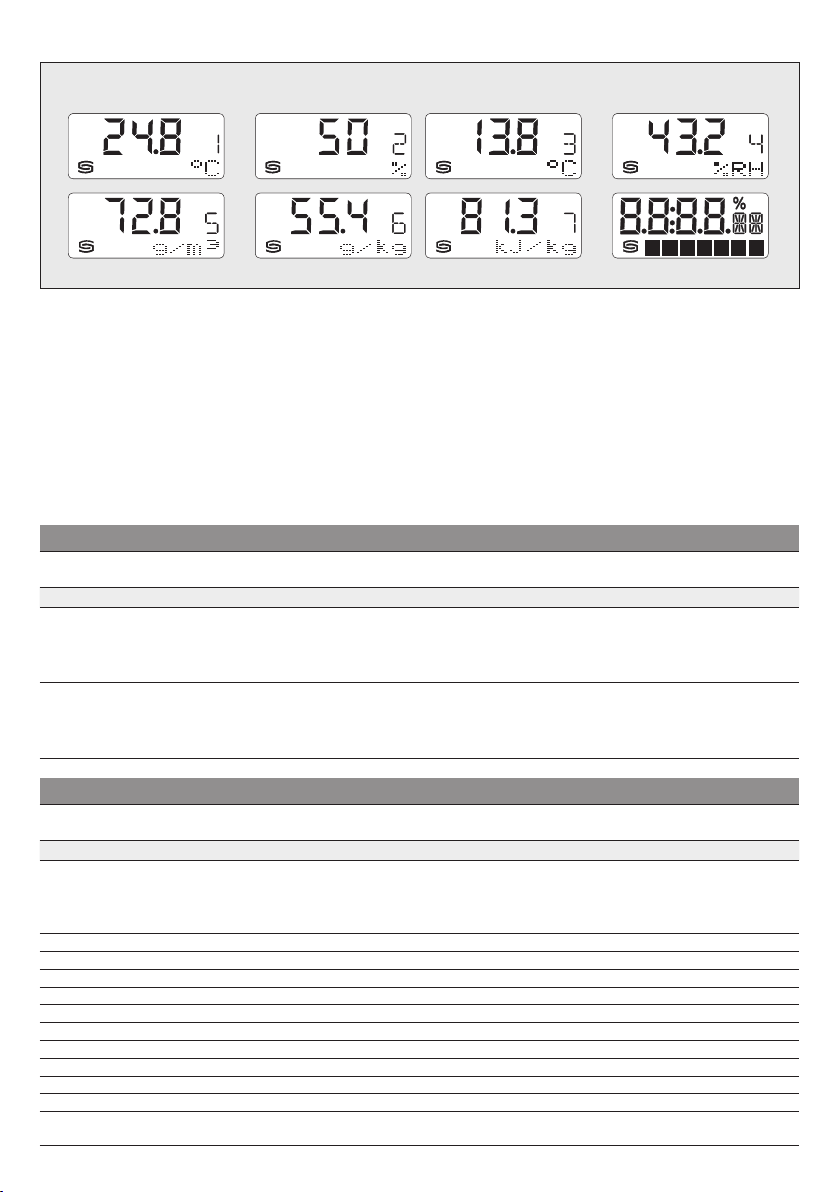
HYGRASGARD
F
®
RFTF - Mo dbus
Rev. 2019 - V23
Affichage
dimensions de sortie alternatives
Par déf aut, les valeurs de mesur e suivantes sont aff ichées
les unes après les a utres
unités correspondantes dans la première lig ne:
Température
Un écran rétr o-éclairé est disponible pour un e meilleure
lisibilit é. Via l'interf ace Modbus, l'écran peut aussi bien être
programmé
segments
en °C,
de manière individuelle
que dans la zone de ma trice de point
HYGRASGARD® RFT F - Modbus
Type ⁄ WG01 plage de mesure ⁄ affichage
de manière cyclique
humidité relative
ave c les
en % h.r.
dans la zone à 7 et 14
.
Sonde d'humidité et de température ambiante
humidité (commutable) température
Via l'int erface Modbus, l'affichag e d'une
dimension de sortie alternative
programmée au lieu de l'affichage standard.
La valeur indice s'a ffiche dans la p remière
ligne et l'unité correspondante est a ffic hée
de manière statique
L'indice caractérise le type d'aff ichage :
RFTF - Modbus
RFTF-MODBUS 0...100 % h.r. (default)
RFTF-MODBUS LCD
0...80 g ⁄ kg (MV )
3
0...80 g ⁄ m
0...85 kJ ⁄ kg (ENT.)
–20...+80 °C (T P)
0...100 % h.r. (default)
0...80 g ⁄ kg (MV )
0...80 g ⁄ m
0...85 kJ ⁄ kg (ENT.)
–20...+80 °C (T P)
(a .F. )
3
(a .F. )
RFTF - M odbus
Indice 1
peu t êt re
dans la seconde lig ne.
sortie
écran
= température en °C
Indice 2
= valeur de consigne du
potentiomètre en
Indice 3
= point de r osée en
Indice 4
= humidité relative enn
Indice 5
= humidité absolue en
Indice 6
= rapport de mélange en
Indice 7
= enthalpie en
kJ ⁄ kg
référence
0...+5 0 °C Modbus 1201-42B6-6000-000
0...+5 0 °C
Modbus ■ 1201-42B6-7000-000
écran
%
°C
% h.r.
g ⁄ m³
g ⁄ kg
HYGRASGARD® RFT F - Modbus
Type ⁄ WG01 plage de mesure ⁄ affichage
Sonde d'humidité et de température ambiante (avec éléments de commande)
humidité (commutable) température
RFTF - Modbu s - xx
RFTF-MODBUS
RFTF-MODBUS
RFTF-MODBUS
RFTF-MODBUS
RFTF-MODBUS
RFTF-MODBUS
RFTF-MODBUS
RFTF-MODBUS
RFTF-MODBUS
RFTF-MODBUS
RFTF-MODBUS
Équipement : P
P
P
LCD
P 5L
P 5L
LCD
P D5
P D5 5L
P T D5 5L
P T
P T
LCD
P T 5L
P T 5L
LCD
0...100 % h.r. (default)
0...80 g ⁄ kg (MV )
3
0...80 g ⁄ m
0...85 kJ ⁄ kg (ENT.)
–20...+80 °C (T P)
(a .F. )
(5 x comme plus haut) (1x comme plus haut)
(5 x comme plus haut) (1x comme plus haut)
(5 x comme plus haut) (1x comme plus haut)
(5 x comme plus haut) (1x comme plus haut)
(5 x comme plus haut) (1x comme plus haut)
(5 x comme plus haut) (1x comme plus haut)
(5 x comme plus haut) (1x comme plus haut)
(5 x comme plus haut) (1x comme plus haut)
(5 x comme plus haut) (1x comme plus haut)
(5 x comme plus haut) (1x comme plus haut)
= poten tiomètre (régleur de consigne)
T
= poussoir de présence
sortie
écran
référence
0...+5 0 °C Modbus 1201-42B6-6001-005
Modbus ■ 1201-42B6-7001-005
Modbus 1201-42B6-6119-005
Modbus ■ 1201-42B6-7119-005
Modbus 1201-42B6-6012-841
Modbus 1201-42B6-6120-841
Modbus 1201-42B6-6121-841
Modbus 1201-42B6-6047-005
Modbus ■ 1201-42B6-7047-005
Modbus 1201-42B6-6051-005
Modbus ■ 1201-42B6-7051-005
D5
= commutateur rotatif à 5 positions
5L = affichage DEL multicolore (5x)
26

HYGRASGARD
ON DIP A
1 2 3 4 5 6
ON DIP B
F
®
RFTF - Mo dbus
| Configuration
ADRESSE DU BUS
Adres se du bus
(code binaire, valance r églable d e 1 à 247)
DIP 1 DIP 2 DIP 3 DIP 4 DIP 5 DIP 6 DIP 7 DIP 8
128 64 32 16 8 4 2 1
O N O N
suit l'adresse Mo dbus 128 + 64 + 1 = 193
L'adresse de l'appareil
Position interrupteur 1 à 8 – voir tableau au verso !
L'adresse 0 est réservée pour des messages de broadcast, les adresses dépassant 247 ne doivent pas être occupées et sont
ignorées par l'appareil. Les interrupt eurs DIP sont codés en binaire avec les valences suivantes :
DIP 1 =
DIP 2 =
DIP 3 = 32 ............ DIP 3 = OFF
DIP 4 = 16 ............ DIP 4 = OFF
DIP 5 = 8 ............ DIP 5 = OFF
DIP 6 = 4 ............ DIP 6 = OFF
DIP 7 = 2 ............ DIP 7 = OFF
DIP 8 =
OFF OFF OFF OFF OFF
dans une plage de
128
............ DIP 1 = ON
64
............ DIP 2 = ON
1
............ DIP 8 = ON L'exemple montr e
1 à 247
O N
(format binair e) est réglée via l'interrupteur DIP [A].
128 + 64 + 1 = 193
MODBUS
Interrupteur DIP [A
]
1 2 3 4 5 6 7 8
comme adresse Modbus.
PARAMÈTRES DU BUS
Taux de transfer t
(réglable)
9600 Baud
19200 Baud
38400 Baud
réservé
Parité
(réglable)
EVEN
(pair)
ODD
(impair)
Le
taux de Baud
On peut r égler 9600 Baud, 19200 Baud ou 38400 Baud – voir tableau !
La
parité
On peut r égler
La
protection par parité
On peut r égler une correction d'erreur (sécurisation par parité)
c.-à.-d. aucune sécurisation par parité – voir tableau !
Le mode 8N1 est activé via la pos. 5 de l'inter rupteur DIP [B].
Le fonctionnement de la pos. 3 (parit é) et de la pos. 4 (protection par parit é) de l'interrupteur DIP [B] est ainsi désactivé.
8N1 est réglable en mode actif ou inactif (par défaut) – voir tableau !
La
terminaison du bus
On peut r égler
En cas de modification des paramètres du bus et de l'adresse du bus, les appareils avec
affichent les paramètres correspondants à l'écran pour env. 30 secondes.
(vitesse de transfer t) est réglé via les pos. 1 et 2 de l'interrupteur DIP [B].
est réglée via la pos. 3 de l'interrupteur DIP [B].
EVEN (pair e)
active
DIP 1 DIP
2
O N
OFF
O N O N
O N
OFF
OFF OFF
Protection par parité
DIP
3
(on / off)
act if
O N
(1 bit stop)
inactif
OFF
ou
(sécurité par parité) est activée via la pos. 4 de l'interr upteur DIP [B].
est activée par la pos. 6 de l'interrupteur DIP [B].
(résistance de terminaison de bus de 120 Ohm) ou
(2 bit stop)
ODD (impaire)
MODBUS
Interrupteur DIP [B
– voir tableau !
]
8N1-M odus
DIP
4
O N
OFF inactif (par défaut) OFF inactif OFF
active (1 bit d'arrêt)
(on / off)
actif
ou
inactive (2 bits d'arrêt)
inactive
(pas de terminaison de bus) – voir tableau !
affichage sur écran
DIP
O N
5
Terminaison de bus
(on / off)
actif
DIP
6
O N
,
AFFICHAGE DE COMMUNICATION
La communication est signalée par deux voyants DEL. Les télégrammes dont la réception est bonne sont signalés
indépendamment de l'adresse de l'appareil par l'allumage du voyant ver t. Les télégrammes erronés ou les télégrammes
d'exception Modbus déclenchés sont représentés par l'allumage du voyant rouge.
DIAGNOSTIC
La fonction de diagnostic de défauts est intégrée
27

HYGRASGARD
F
®
RFTF - Mo dbus
| Configuration
AFFICHAGE SUR L'ÉCRAN
Par défaut, les valeurs de mesure suivantes sont affichées les unes après les autres de manière
correspondantes dans la première ligne:
Température
Via l'interface Modbus, l'affichage d'une dimension
Point de rosée
umidité relative
h
La valeur indice s'affiche dans la première ligne et l'unité correspondante est affichée de manière
L'indice carac térise le type d'affichage, p. ex. températur e de point de rosée (voir le tableau « Function 06 Write Single Register »).
Via l'interface Modbus, l'affichage de l'écran peut aussi bien êtr e programmé dans la zone à 7 et à 14 segments que dans la zone
de matrice de point
Pour
Les registres 4x0002 à 4x0012 contiennent des informations sur les carac tères et segments à af ficher.
La zone de matrice de points est également programmable dans le réglage par défaut (le registre 4x0 001 contient la valeur 0).
Dans la zone à 7 segments, la valeur de mesure actuelle s'af fiche automatiquement.
Structure du modèle du segment (registre 4x0005)
Bit 0 ......
Bit 1 ......
Bit 2 ......
Bit 3 ......
Bit 4 ......
Bit 5 ......
Bit 6 ......
Bit 7 ......
Bit 8 ......
Bit 9 ......
Bit 10 ....
Bit 11 ....
Bit 12 ....
Bit 13 ....
Bit 14 ....
Bit 15 ....
Structure du modèle à 14 segment s (registre 4x0003 et 4x0004)
Bit 0 ......
Bit 1 ......
Bit 2 ......
Bit 3 ......
Bit 4 ......
Bit 5 ......
Bit 6 ......
Bit 7 ......
Bit 8 ......
Bit 9 ......
Bit 10 ....
Bit 11 ....
Bit 12 ....
Bit 13 ....
Bit 14 ....
Bit 15 ....
en °C,
humidité relative
(en °C),
rapport de mélange
(en %),
température
.
Il est ainsi possible, par exemple, d'afficher les messages de l'API.
l'affichage librement programmable
Dot A
Dot B
Dot C
Dot D
Dot DP
Pourcentage
- -
- -
- -
- -
- -
- -
- -
- -
- -
- -
A
B
C
D
E
F
G
G'
H
I
J
K
L
M
- -
- -
en % h.r. (For mat d'af fichage de 1/10 °C resp. 1/10 % h.r.)
Valeur d'affichage :
Indice :
Unité :
Point A
Matrice de points
H
F B
G G'
E C
M
de sortie alternative
(en g ⁄ kg),
(en °C) ou
, le registre 4x0001 (valeur d'affichage physique) doit contenir la valeur 10.
humidité absolue
valeur de consigne du potentiomètre
13.8
1
°C
Point B Point C Point D Pourcentage
A
D
Point DP
A B C D E F G
I
L
peut être programmé au lieu de l'affichage standard:
(en g ⁄ m3),
J
K
enthalpie
(en % )
Exemple de signes
Degré Celsius (°C)
14 segments 1:
227 57
(registre 4x003) (registre 4x004)
cyclique
(en kJ ⁄ kg),
statique
avec les unités
dans la seconde ligne.
14 segments 1
14 segments 2
14 segments 2:
28

Sign
Espace
!
“
#
$
%
&
(
)
*
+
,
-
.
/
0
1
2
3
4
®
RFTF - Mo dbus
ASCII
53
54
55
56
57
58
59
60
61
62
63
64
65
66
67
68
69
70
71
72
| Configuration, Télégrammes
Sign
5
6
7
8
9
:
;
<
=
>
?
@
A
B
C
D
E
F
G
H
ASCII
73
74
75
76
77
78
79
80
81
82
83
84
85
86
87
88
89
90
91
93
Sign
I
J
K
L
M
N
O
P
Q
R
S
T
U
V
W
X
Y
Z
[
]
ASCII
94
95
96
97
98
99
100
101
102
103
104
105
106
107
108
109
110
111
112
113
HYGRASGARD
F
Tableau des codes ASCII pour la zone d'af fichage de la matrice de points
ASCII
32
33
34
35
36
37
38
40
41
42
43
44
45
46
47
48
49
50
51
52
Les caractères ASCII ou de contrôle qui ne figurent pas dans le tableau sont présentés par des espaces.
Sign
^
_
\
a
b
c
d
e
f
g
h
i
j
k
l
m
n
o
p
q
ASCII
114
115
116
117
118
119
120
121
122
123
124
125
129
132
142
148
153
154
223
Sign
r
s
t
u
v
w
x
y
z
{
|
}
ü
ä
Ä
ö
Ö
Ü
°
AFFICHAGE LED
Affichage individuel des LED (registre 4x0014 = 0)
La couleur et la luminosité des LED peuvent être commandées individuellement via Modbus.
Avec les registres 4x0015 bis 4x0019 (LED x Mode, x=1…5), l'
différents types de clignotement), resp. le poussoir de présence peut être affecté à une LED.
Avec les registres 4x0020 à 4x0024 (LED x couleur, x=1...5), la
(voir tableau). Le chiffre des dizaines correspond à la couleur et le chiffre des unités à la luminosité. Concernant l'affectation des
couleurs et de la luminosité, la valeur 100 se réfère au registre des couleurs des LED correspondant (4x0025 à 4x0039) avec la
possibilité d'affecter les trois couleurs rouge, verte et bleue de manière individuelle.
Les affichages à LED sont activés et désactivés individuellement par le télégramme MODBUS
Les réglages de registre ci-contre
correspondent à l'exemple suivant
pour différents messages de service et de dérangement :
LED 1 rouge
LED 2 jaune
LED 3 blanche
LED 4 verte
LED 5 blanche
bouton-poussoir
Alarme – clignote rapidement
Avertissement– clignote lentement
Service
Service
Présence y compris combinaison avec
état d'affichage de chaque LED
couleur et la luminosité de la LED
4x0 014
= 0 (LED adressables individuellement)
4x0015
= 4 (clignote rapidement)
4x0016
= 2 (clignote moyennement)
4x0017
= 0 (lumière permanente)
4x0018
= 0 (lumière permanente)
4x0019
= 5 (changement d'ét at via poussoir de présence)
4x0020
= 35 couleur rouge
4x0021
= 25 couleur jaune
4x0022
= 5 couleur blanche
4x0023
= 55 couleur verte
4x0024
= 5 couleur blanche
29
peut être réglé (lumière permanente/
peuvent être réglées
« Function 05 Write Single Coil
».
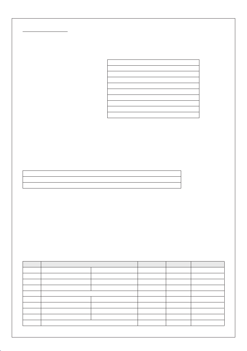
HYGRASGARD
F
Affichage bargraphe des LED (registre 4x0014 = 1 à 4)
Les LED sont connectées dans un ordre d'affichage et indiquent la valeur inscrit e dans le registr e 4x0013 (valeur bargraphe)
en couleur. Certains niveaux intermédiaires sont représentés au moyen de variations de luminosité.
Le choix des couleurs du bargraphe est définissable via le registre 4x0014 (mode bargraphe) et peut être réglé de manière
individuelle au moyen du registre des couleurs des LED (4x0025 à 4x0039).
Les réglages de registre ci-contre
correspondent à l'exemple suivant pour un
affichage à lampes défini par l'utilisateur
LED 1 rouge (registre des couleurs)
LED 2 jaune
LED 3 jaune-verte
LED 4 verte
LED 5 verte
®
RFTF - Mo dbus
| Configuration, Télégrammes
4x0013
:
4x0 014
4x0020
4x0021
4x0022
4x0023
4x0024
4x0025
4x0026
4x0027
Valeur d'affichage
= 4
= 100 (couleur rouge définie par l'utilisateur)
= 25 couleur jaune
= 45 couleur jaune-verte
= 55 couleur verte
= 55 couleur verte
= 40 registre des couleurs rouge
= 1 registre des couleurs verte
= 2 registre des couleurs bleu
POTENTIOMÈTRE ET COMMUTATEUR ROTATIF
La position du potentiomètr e est dét ectée dans une plage de 0 à 100 % et af fichée via le registre 3x0005 (valeur de consigne du
poten tiomètre). La position du commutateur rot atif (en option) peut être int errogée via le registre 3x0010 (commut ateur rotatif)
dans les positions 1 à 5.
POUSSOIR DE PRÉSENCE
Le poussoir de présence est représenté via les registres 1x0001 à 1x0003. Si le bouton-poussoir n'est assigné à aucune LED,
le mode LED diffère de la valeur 5
(
1x0001 Bouton poussoir pressé = 1, détection via changement de front
1x0002 Bouton poussoir libéré = 1, détection via changement de f ront
1x0003 État du bouton-poussoir, état actuel du bouton-poussoir au moment de la requête
Les informations concernant les boutons-poussoirs déclenchées par un changement de front sont sauvegardées jusqu'au
télégramme de requête Modbus suivant «
détectée de manière sûre même lors de longs balayages de bus (par ex. 1 seconde).
En cas d'af fectation du bout on-poussoir à une LED (
s'effectue automatiquement à chaque pression du bouton-poussoir. La LED correspondante doit être activée via la fonction 05
Write Single Coil.
La requête de l'état de la LED est possible via le r egistre 1x0001.
Le registre 1x0002 est sans fonction.
Le registre 1x0003 indique l'état actuel du bouton-poussoir au moment de la requête.
Par ailleurs, l'état de la LED peut en outre être sélectionné ou supprimé via la fonction 05 Writ e Single Coil Bit 6.
) les états des boutons-poussoirs peuvent être détectés par les registres suivants :
Function 02 Read Discrete Input
Mode LED correspond à la valeur 5
» , si bien que l'activation des boutons-poussoirs est
), un changement de l'état de la LED
TÉLÉGRAMMES
Function 04 Read Input Register
Registre Paramètre Data Typ e Value Range
3x0001
3x0002
3x0003
3x0004
3x0005
3x0006
3x0007
3x0008
3x0009
3x0010
Température
Température
Humidité relative
Humidité relative
Potentiomètre de consigne Signed 16 Bit 0...1000 0.0...100.0 %
Point de rosée Valeur calculée Signed 16 Bit 0...500 0.0...+50.0 ° C
Humidité absolue Valeur calculée Signed 16 Bit 0...80 0 0.0...80.0 g/m
Rappor t de mélange Valeur calculée Signed 16 Bit 0...800 0.0...80.0 g /kg
Enthalpie Valeur calculée Signed 16 Bit 0...8 50 0.0...85.0 kJ/k g
Commutateur rotatif Unsigned 8 Bit 0...4 Positions 1...5
Balayage 4 s
Filtrage 32 s
Balayage 4 s
Filtrage 32 s
30
Signed 16 Bit 0...5 00 0.0...+50.0 °C
Signed 16 Bit 0...5 00 0.0...+50.0 °C
Signed 16 Bit 0...1000 0.0...100.0 % h.r.
Signed 16 Bit 0...1000 0.0...100.0 % h.r.
3

HYGRASGARD
F
®
RFTF - Mo dbus
| Télégrammes
Function 06 Write Single Register & Function 16 Write Multiple Register
Registre Paramètres (écran) Data Type Value Range
4x0001
4x0002
4x0003
4x0004
4x0005
4x0006
4x0007
4x0008
4x0009
4x0010
4x 00 11
4x0012
4x0040
Valeur d'affichage physique Indice à l'écran Unsigned 8 Bit 0 …10 0…10
Affichage standard (cyclique):
Température en °C,
Humidité relative en % h.r.
Affichage alternatif (statique):
Température en °C 1 1
Valeur de consigne du potentiomètre en %
Point de rosée en °C 3 3
Humidité relative en % h.r. 4 4
Humidité absolue en g/m
Rappor t de mélange en g/kg 6 6
Enthalpie en kJ/kg 7 7
Affichage librement configurable – 10
Valeur 7 segments Signed 16 Bit -999…9999 -999…9999
14 segment s modèle 1 voir le graphique Unsigned 16 Bit voir le modèle binair e
14 segment s modèle 2 voir le graphique Unsigned 16 Bit voir le modèle binair e
Modèle du segment Unsigned 16 Bit voir le modèle binaire
Matrice de poin ts caractère A Unsigned 8 Bit 0…255 Caractères ASCII
Matrice de poin ts caractère B Unsigned 8 Bit 0…255 Caractères ASCII
Matrice de poin ts caractère C Unsigned 8 Bit 0…255 Caractères ASCII
Matrice de poin ts caractère D Unsigned 8 Bit 0…255 Caractères ASCII
Matrice de poin ts caractère E Unsigned 8 Bit 0…25 5 Caractères ASCII
Matrice de poin ts caractère F Unsigned 8 Bit 0…255 Caractères ASCII
Matrice de poin ts caractère G Unsigned 8 Bit 0…255 Caractères ASCII
Luminosité rétroéclairage LCD Unsigned 8 Bit 0...63 0...100%
3
– 0 Réglage par déf aut
2 2
5 5
Registre Paramètres (LED) Data Typ e Value Range
4x0013
4x0 014
4x0015
4x0016
4x0017
4x0018
4x0019
Valeur bargraphe (LED) Unsigned 16 Bit 0…1000 0…1000
Mode bargraphe Unsigned 8 Bit 0…4
LED commandées indépendamment 0 Réglage par défaut
Bargraphe A Vert - vert - j aune - jaun e - rouge
Bargraphe B Vert - jaune - r ouge
Bargraphe C Bleu - bleu-rouge - rouge
Bargraphe D Couleur du
Mode LED 1 Unsigned 8 Bit 0…5 Défaut = 0
Mode LED 2 Unsigned 8 Bit 0…5 Défaut = 0
Mode LED 3 Unsigned 8 Bit 0…5 Défaut = 0
Mode LED 1 Unsigned 8 Bit 0…5 Défaut = 0
Mode LED 5 Unsigned 8 Bit 0…5 Défaut = 0
Lumière permanente 0 Réglage par défaut
Clignotements brefs 1
Clignotements moyens 2
Clignotements longs 3
Clignotements rapides 4
Changement avec bouton-poussoir 5
(ampoule LED)
(tout es les LED de même couleur)
(tout es les LED de même couleur)
regist re des couleurs LED
31
1
2
3
4

HYGRASGARD
F
®
RFTF - Mo dbus
| Télégrammes
Function 06 Write Single Register & Function 16 Write Multiple Register
Registre Paramètres (LED) Data Typ e Value Range
4x0020
4x0021
4x0022
4x0023
4x0024
4x0025
4x0026
4x0027
4x0028
4x0029
4x0030
4x0031
4x0032
4x0033
4x0034
4x0035
4x0036
4x0037
4x0038
4x0039
Couleur LED 1 Unsigned 8 Bit 0 …10 0 Défaut = 0
Couleur LED 2 Unsigned 8 Bit 0 …10 0 Défaut = 0
Couleur LED 3 Unsigned 8 Bit 0 …10 0 Défaut = 0
Couleur LED 4 Unsigned 8 Bit 0 …10 0 Défaut = 0
Couleur LED 5 Unsigned 8 Bit 0 …10 0 Défaut = 0
Blanc 0…9
Jaune 10 …19
Orange 20…29
Rouge 3 0…39
Jaune-vert 40…49
Vert 50…59
Turquoise 60…69
Bleu 70…79
Violet 80…89
Registre des couleurs
Registre des couleurs LED 1 Rouge 0…6 3
Registre des couleurs LED 1 Vert 0…63
Registre des couleurs LED 1 Bleu 0…63
Registre des couleurs LED 2 Rouge 0…6 3
Registre des couleurs LED 2 Vert 0…63
Registre des couleurs LED 2 Bleu 0…63
Registre des couleurs LED 3 Rouge 0…6 3
Registre des couleurs LED 3 Vert 0…63
Registre des couleurs LED 3 Bleu 0…63
Registre des couleurs LED 4 Rouge 0…6 3
Registre des couleurs LED 4 Vert 0…63
Registre des couleurs LED 4 Bleu 0…63
Registre des couleurs LED 5 Rouge 0…6 3
Registre des couleurs LED 5 Vert 0…63
Registre des couleurs LED 5 Bleu 0…63
100
foncé = 0
clair = 9
foncé = 10
clair = 19
foncé = 20
clair = 29
foncé = 30
clair = 39
foncé = 40
clair = 49
foncé = 50
clair = 19
foncé = 60
clair = 69
foncé = 70
clair = 79
foncé = 80
clair = 89
32

HYGRASGARD
F
®
RFTF - Mo dbus
| Télégrammes
Function 02 Read Discrete Input
Registre Paramètre Da ta Type Value Range
0x0001
0x0002
0x0003
0x0004
0x0005
0x0006
0x0007
LED 1 multicolore Bit 0 0 / 1 OF F - ON
LED 2 multicolore Bit 1 0 / 1 OF F - ON
LED 3 multicolore Bit 2 0 / 1 OF F - ON
LED 5 multicolore Bit 3 0 / 1 OF F - ON
LED 6 multicolore Bit 4 0 / 1 OF F - ON
Set / Clear
État de la LED du bouton-poussoir
Luminosité rétroéclairage LCD Bit 6 0 / 1 OFF - ON
Bit 5 0 / 1 CLE AR - SET
Function 02 Read Discrete Input
Registre Paramètre Da ta Type Value Range
1x0001
1x0002
1x0003
Note : Les adresses 1x000 4...1x0008 sont lues avec la valeur « 0 ».
Function 08 Diagnostics
Les
codes sous-fonction suivants
Code sous-
fonction
00
01
04
10
11
12
13
14
15
Poussoir de présence /
État de la LED
Poussoir de présence libéré Bit 1 0 / 1 OF F - ON
Poussoir de présence actuel Bit 2 0 / 1 OF F - ON
Paramètre Data Ty pe Réponse
Écho des données d'émission
(loopback-rebouclage)
Redémarrage Modbus
(Reset Listen Only Mode –
Réinit Mo de Écoute Seule)
Activation Listen Only Mode
(mode Éc oute seule)
Efface compteur Télégramme d'écho
Compt eur Télégrammes de bus Unsigned 16 Bit Tous les télégrammes de bus valides
Compteur Erreur de communication
(Parité, CRC, erreur Frame, etc.)
Compteur Messages d'exception Unsigned 16 Bit Compteur d'erreurs
Compteur Télégrammes esclaves Unsigned 16 Bit Télégrammes esclaves
Compteur Télégrammes sans réponse Unsigned 16 Bit Message de Broadcast (adresse A)
pressée /
activée
sont pris en charge
Bit 0 0 / 1 OFF - ON
Données d'écho
Télégramme d'écho
Pas de réponse
Unsigned 16 Bit Télégrammes de bus erronés
Function 17 Report Slave ID
Structure du télégramme de réponse
n° de byte Paramètre Dat a Type Réponse
00
01
02
03
04
05
06
Nombre de bytes Unsigned 8 Bit 6
ID esclave (Device Type) Unsigned 8 Bit 11 =
ID esclave (Device Class) Unsigned 8 Bit 20 =
Statut Unsigned 8 Bit 255 = RUN, 0 = STOP
Numéro de version (release) Unsigned 8 Bit 1…9
Numéro de version (version) Unsigned 8 Bit 1…99
Numéro de version (index) Unsigned 8 Bit 1
33
HYGRASGARD® MODBUS
HYGRASGARD® /
HYGRASREG
®

HYGRASGARD
F
Structure générale du bus
®
RFTF - Modbus
| Installation
MODBUS
RTU-Master
passif
LA LA
Tronçon
(câble de
dériv ation)
Slave 1 Slave 2
Topologie du bus avec résistances de charge et polarisation
Raccord actifRaccord
RS-485
Ligne principale
(câble principal)
Slave n
MODBUS
RTU-Master
Tronçon :
moins de 20 m
A (D1) D+
B (D0) D–
Poly-raccord n :
moins de 40 m / n
5 V
Résistance de pull-up /
polarisation
Résistance de pull-down /
polarisation
Fin de ligneFin de ligne
Fin de ligneFin de ligne
Common
(GND)
Slave 1 Slave 2
Les résistances de charges ne doivent être placées qu'aux extrémités de la ligne de bus.
Dans les réseaux sans repeater, un maximum de 2 terminaisons de ligne est autorisé.
La terminaison de ligne peut être activée sur l'appareil via le DIP 6. Les résistances de polarisation
pour la définition du niveau du bus au repos sont généralement activées au maître Modbus / repeater.
Le nombre maximum de correspondant s par segment Modbus est de 32 appar eils.
Pour des grands nombres de corr espondants, le bus doit êt re réparti en plusieurs segments par l'intermédiair e de repeaters.
L'adresse des correspondants peut être fixée de 1 à 247.
Pour la ligne de bus, on peut utiliser un câble avec ligne de données / alimentation tension câblées par paire et
treillis de blindage en cuivre. La capacité linéique de la ligne doit rester inférieure à 100 pF/m (p.ex. ligne Prof ibus).
34

Montage et mise en service
F
Les raccordements électriques doivent être exécutés HORS TENSION.
Veillez à ne brancher l’appar eil que sur un réseau de très basse tension
de sécur ité. Nous déclinons toute responsabilité ou garantie au titre
de tout dommage consécutif pr ovoqué par des erreur s commises sur
cet appareil. L'installation et la mise en service des appar eils doit être
effectuée uniquement par du personnel qualifié. Seules les
données techniques et les conditions de raccordement indiquées sur
l’étiquette signalétique de l’appareil ainsi que la notice d’instruction sont
applicables. Des différences par rapport à la présentation dans le
catalogue ne sont pas mentionnées explicitement et sont possibles suite
au progrès technique e t à l’amélioration continue de nos produits. En cas
de modif ications de s appareils pa r l’utilisate ur, tous d roits de gar antie ne
seront pas reconnus. L’utilisa tion de l’appareil à proximité d’appareils qui
ne sont pas conformes aux directives « CEM » pourra nuire à son mode
de fonc tionnement. Cet appareil ne devra pas être utilisé à des fins de
surveillance qui visent uniquement à la protection des personnes contre
les dangers ou les blessures ni comme interrupteur d’arr êt d’urgence
sur des ins tallations ou des machines ni pour des fonc tions relatives à
la sécurité comparables.
Il est possible que les dimensions du boîtier et des accessoires du boîtier
divergent légèrement des indications données dans cette notice.
Il est interdit de modifier la présente documen tation.
En cas de réclamation, les appareils ne sont r epris que dans leur
emballage d’origine et que si tous les éléments de l’appareil sont
complets.
Généralités
F
Seules les CGV de la société S+S, les « Conditions générales de livraison du ZVEI pour produit s et prestations de l’industrie électronique »
ainsi que la clause complémentaire « Réserve de propriété étendue » s’appliquent à toutes les relations commerciales entre la société S+S et
ses clients.
Il convient en outre de respecter les points sui vants :
– Avant de procéder à tout e installation et à la mise en servic e, veuillez lire attentivement la présente no tice et t outes les consignes qui y sont
précisées !
– Les raccordements électriques doivent être exécutés HORS TENSION. Ne branchez l’appar eil que sur un réseau de très basse tension de sécurit é.
Pour éviter des endommagements ⁄ erreurs sur l’appareil (par ex. dus à une induction de tension parasite), il est conseillé d’utiliser des câbles
blindés, ne pas poser les câbles de sondes en parallèle avec des câbles de puissance, les directi ves CEM sont à respecter.
– Cet appareil ne doit être utilisé que pour l’usage qui est indiqué en respectant les règles de sécurité correspondantes de la V DE,
des Länders, de leurs organes de surveillance, du TÜV et des entreprises d’approvisionnement en énergie locales. L’acheteur doit respect er les
dispositions relatives à la construction et à la sécurité et doit éviter toutes sort es de risques.
– Nous déclinons toute responsabilité ou garantie pour les défauts et dommages r ésultant d’une utilisation inappropriée de cet appareil.
– Nous déclinons toute responsabilité ou garantie au tit re de tout dommage consécutif provoqué par des erreurs commises sur cet appareil.
– L’installation et la mise en service des appareils doit être effectuée uniquement par du personnel qualifié
– Seules les données techniques et les conditions de raccordement indiquées sur la notice d’instruction accompagnant l’appareil sont applicables,
des différences par r appor t à la présentation dans le catalogue ne sont pas mentionnées explicitement et sont possibles suit e au progrès
technique et à l’amélioration continue de nos produits.
– En cas de modifications des appar eils par l’utilisateur, tous droits de garantie ne ser ont pas reconnus.
– Cet appareil ne doit pas être utilisé à proximité des sources de chaleur (par ex. radiateurs) ou de leurs flux de chaleur, il fau t impérativement
éviter un ensoleillement direct ou un rayonnement thermique provenant de sources similaires (lampes très puissantes, projecteurs à halogène).
– L’utilisation de l’appareil à proximité d’appareils qui ne son t pas conformes aux dir ectives « CEM » pourra nuire à son mode de fonctionnement.
– Cet appareil ne devra pas être utilisé à des f ins de sur veillance qui visent à la pr otection des personnes contre les dangers ou les blessures ni
comme interr upteur d’arrêt d’urgence sur des installations ou des machines ni pour des fonctions relatives à la sécurité comparables.
– Il est possible que les dimensions du boîtier et des accessoires du boîtier divergent légèrement des indications données dans cette notice.
– Il est interdit de modifier la présente documentation.
– En cas de réclamation, les appareils ne sont repris que dans leur emballage d’origine et si tous les éléments de l’appareil sont complets.
La mise en service ne doit être effectuée que par du personnel qualifié!
Avant de procéder à l’installation et à la mise en service, veuillez lir e attentivement la présente notice et toutes les
consignes qui y sont précisées !
Consignes pour l’installation mécanique :
Effectuer le montage en tenant compte des dispositions et règles s
tandards à ce titre applicables pour le lieu de mesur e (par ex. des règles
de soudage, etc.) Sont not amment à considérer :
– Mesur e technique de tempéra tures selon VDE ⁄ VDI, dir ectives,
ordonnances sur les instruments de mesure pour la mesure de
températures.
– Les directiv es « CEM », celles-ci sont à respecter.
– Ne pas poser les câbles de sonde en parallèle avec des câbles de
puissance.
– Il est conseillé d’u tiliser des câbles blindés, ce faisant racco rder l’une
des extrémit és du blindage sur le DDC ⁄ API.
Effectuer l’installation en respectant la conformité des paramètr es
techniques correspondants des thermomètres aux conditions d’utilisation
réelles, notamment :
– Plage de mesure
– Pression maximale admissible, vitesse d’écoulement
– Longueur de montage, dimensions des tubes
– Éviter les oscillations, vibrations, chocs (< 0,5 g)
Consignes de mise en service:
Cet appareil a ét é étalonné, ajusté et testé dans des conditions
normalisées. En cas de fonctionnement dans des conditions différentes,
nous recommandons un premier r églage manuel sur site lor s de la
mise en ser vice et à inter valles r éguliers par la suite.
35

HYGRASGARD
3
4
5
1 2
r.H .
°C
offset
123456
ON DIPB
12345678
ON DIPA
°Cr.H .
Plug for
display
+UB 24V AC/DC
–UB GND
RS485 Modbus A
RS485 Modbus B
Shielding
Potentiometer
Presence
button
Plug for display
contact is
on the right side
DIP A: Bus address
DIP B: Bus parameters
(Baud rate, parity ...)
Telegram indicator
Reception (LED green)
Error (LED red)
LED (internal status)
Offset correction
temperature: ± 10°C
Offset correction
humidit y: ± 10% r.H.
Turn switch
r
Калибруемый комнатный датчик
корп усе (B aldur 2) измеряе т относит ель ную в лаж нос ть и температу ру воз духа в помещении. На основе измеренных значений далее в ычис ляю тся
различ ные па раме тры. Через шину Mod bus можно сч иты ват ь следующие параме тры: относ ите льн ую влажн ост ь [%], абс олю тну ю вла жно сть [г ⁄ м³],
соотн ошен ие ком поне нтов смеси [г ⁄ кг], точк у рос ы [°C], энт аль пию [к Дж ⁄ кг] (без учёта а тмо сфер ного д авл ения ) и темп ературу в помещении [°C].
При этом имеются на выбор элементы управления: задающий потенциометр, 5-полюсный поворотный выключатель и кнопка присутствия. Для вывода
температуры / относительной влажности / абсолютной влажнос ти / точки росы / соотношения компонентов смеси / энта льпии и заданного значения имеются
опциональные приборы с жидкокристаллическим дисплеем для отображения измеренных значений. Рабочие состояния показаны максимум 5 многоцветными
светодиодными индикаторами. Управление индикацией (ЖК-дисплеем), а также считывание измеренных и рабочих значений осуществляется через
интерфейс шины Modbus.
®
RFTF - Mo dbus
HYGRASGARD®
Rev. 2019 - V23
RFTF - M odbus с подключением к шине Modbus, на выбор с диспле ем или без нег о, в эле гантном
ТЕХНИЧЕСКИЕ ДАННЫЕ
Элек тро питание: 24Впере м. ток а (±20%) и 15…36В пос т. тока
Потребл яемая мощн ост ь: < 1,0 ВА ⁄ 24 В п ост. то ка; < 2,2 ВА ⁄ 24 В перем. тока
Чувствительный элемент:
Отличительные
особенности:
Диап азон и змерения: 0...100% отн. вл. (в лаж ность)
Погрешность
изме рения влаж ност и: обычно
Погрешность
измерения температ уры: обычно ± 0,2K при +25 °C
Смещ ение н улев ой точки: ±10% отн. вл. (влажность)
Температура хранение: −35...+85 °C;
окружающей среды: эксплуатация: 0...+50 °C
Сред а: чистый воздух и
Параметры шины:
Шинный интерфейс: RS 485,
Протокол шины: Modbus (RTU),
Скорость пере дачи: 9 600, 1920 0, 3840 0бо д
Индикация состояния: Светодиод зеленый = телеграмма действительна
Фильтрац ия сиг нал ов: 4 c / 32 c
Корпус: пластик, акрилонитрил-бу тадиенстирол (ABS),
Размеры: 9 8 x 98 x 33м м (Baldur 2 )
Монт аж:
Долговременная
ста биль ност ь: ±1% в го д
Относительная
вла жность воздуха: < 95% без к онденсации
Класс защиты: III (согласно EN 60 730)
Степень защиты: IP 30 (согл асно EN 60 529)
Нормы: соответствие CE согласно директиве по электромагнитной
Опции:
цифров ой датчик влажности
со встроенным датчиком температуры,
с малым гистерезисом и высокой долговременной стабильностью
определение температуры, относительной влажности,
абсолютной влажности, точки росы, соотношения компонентов
смеси, энтальпии, а также задающий потенциометр,
поворотный выключатель и кнопка присутствия
0...+ 50 °C (тем пера тура )
± 2,0 %
(20...80 % отн. вл.) при +25 °C, иначе ± 3,0 %
± 10 °C (те мпера тур а)
настраивается через потенциометр
неагрессивные
без подачи напряжения
посредством DIP-переключателей
шины активируется DIP-переключателем. Возможно до 32
приборов на одном сег мент е. При больш ем количес тве
приборов следует использовать RS485-трансивер.
диапазон адресов 0...
цветные светодиоды, программируемый
, негорючие газы
(в обесточенном состоянии)
настраиваемый и адресуемый!
с гальванической развязкой
247
с возможностью настройки
Светодиод красный = ошибка телеграммы
цвет– чистый белый (аналогичный RAL 9010)
монт аж на с тен у или в монта жн ую коробк у для скры тог о
монт ажа, Ø55мм, ниж няя часть с ч еты рьмя отве рст иями,
для крепления в вертикально или горизонтально
установленных коробках скрытого монтажа с вводом провода
сзади, с выламываемой заглушк ой для вво да провод а сверху
или сн изу пр и отк рыт ом монтаже.
совм естимос ти 2014 ⁄ 30 ⁄ EU, согласно EN 61326
дисплей с подсветкой,
выре з ок. 36 x 15 мм (Ш x В),
для индикации измеренной влажности и температуры
или выбираемого параметра
или индивидуально программируемого значения
двухстрочный, программируемый,
, оконечная нагрузка
Схема подключения
RFTF- Modbus
DIP A: Bus address
DIP B: Bus parameters
(Baud rate, parity ...)
Telegram indicator
Reception (LED green)
Error (LED red)
LED (internal status)
Offset correction
temperature: ± 10°C
°C
Offset correction
humidit y: ± 10% r.H.
r.H .
Plug for display
contact is
on the right side
Калибровка нулевой точки
Датчики настроены и согласованы на заводе.
Возможна корректировка обоими потенциометрами
смещ ения. Д иапазон на стр ойки сост авл яет ± 10 °C и
± 10 % относительной в лажности.
Индикация
(стандартная)
RFTF - M odbus
Дисплей
36

HYGRASGARD
r
®
RFTF - Mo dbus
Rev. 2019 - V23
Индикация
(
альтернативные выходные величины)
В стандартном исполнении в первой строке поочередно и
циклично
отображаются следующие измеренные значения
с соответствующими единицами измерения:
температура
Улучшенная считываемость благодаря фоновой подсветке.
Посредством шинного интерфейса дисплей можно
индивидуально
поле, т ак и в по ле с точ ечно й матрице й.
(°C),
относительная влажность
программировать как в 7- и 14-сегментном
HYGRASGARD® RFT F - Modbus
Тип ⁄ WG01 Диапазон измерений⁄ индикация
(%)
Датчик влажности и температуры комнатный
влажность (переключаемая) температ ура
Используя шинный интерфейс, вместо
стандартной индикации можно
запрограммировать отображение
альтернативной выходной величины
При эт ом в пер вой строк е
жает ся значение с инд ексом, а во вт орой—
соответствующая единица измерения.
Индекс обозначает тип индикации:
RFTF - Modbus
RFTF-MODBUS 0 …100% отн. вл. (default)
RFTF-MODBUS LCD
0...80г⁄кг (MV)
3
0...80г⁄ м
(a .F. )
0...85кД ж ⁄кг (EN T.)
−20...+80°C ( TP)
0 …100% от н. вл. (default)
0...80г⁄кг (MV)
3
0...80г⁄ м
(a .F. )
0...85кД ж ⁄кг (EN T.)
−20...+80°C ( TP)
RFTF - M odbus
Дисплей
Индекс 1
= темп ерат ура в °C
Индекс 2
= заданное значение
статично
.
отобра-
Выход
потенциометра в
Индекс 3
= точк а росы в
Индекс 4
=
Индекс 5
Индекс 6
смеси в
Индекс 7
Дисплей
относительная влажность в %
=
абсолютная влажность в г ⁄ м³
= оотношение компонентов
= энтальп ия в
Арт. №
г ⁄ кг
°C
кД ж ⁄ кг
%
0...+5 0 °C Modbus 1201-42B6-6000-000
0...+5 0 °C
Modbus ■ 1201-42B6-7000-000
HYGRASGARD® RFT F - Modbus
Тип ⁄ WG01 Диапазон измерений ⁄ индикация
Комнатный контроллеры влажности и температуры
влажность (переключаемая) температура
RFTF - Modbu s - xx
RFTF-MODBUS
RFTF-MODBUS
RFTF-MODBUS
RFTF-MODBUS
RFTF-MODBUS
RFTF-MODBUS
RFTF-MODBUS
RFTF-MODBUS
RFTF-MODBUS
RFTF-MODBUS
RFTF-MODBUS
Комплектация: P
P
P
LCD (5 x см. выше ) (1 x см. выш е) Modbus ■ 1201-42B6-7001-005
P 5L
P 5L
LCD (5 x см. в ыше) (1 x см. выше) Modbus ■ 1201-42B6-7119-005
P D5
P D5 5L
P T D5 5L
P T
P T
LCD (5 x с м. выше ) (1 x см. выш е) Modbus ■ 1201-42B6-7047-005
P T 5L
P T 5L
LCD (5 x см. в ыше) (1 x см. в ыше) Modbus ■ 1201-42B6-7051-005
0 …100% от н. вл. (default)
0...80г⁄кг (MV)
3
0...80г⁄ м
(a .F. )
0...85кД ж ⁄кг (EN T.)
−20...+80°C ( TP)
(5 x см. вы ше) (1 x см. в ыше) Modbus 1201-42B6-6119-005
(5 x см. вы ше) (1 x см. в ыше) Modbus 1201-42B6-6012-841
(5 x см. вы ше) (1 x см. в ыше) Modbus 1201-42B6-6120-841
(5 x см. вы ше) (1 x см. в ыше) Modbus 1201-42B6-6121-841
(5 x см. вы ше) (1 x см. в ыше) Modbus 1201-42B6-6047-005
(5 x см. вы ше) (1 x см. в ыше) Modbus 1201-42B6-6051-005
= потенциометр (задатчик)
T
= кнопка присутствия
37
Выход
Дисплей
Арт. №
0...+5 0 °C Modbus 1201-42B6-6001-005
D5
= поворотный выключатель, 5-ступенчатый
5L = светодиодные индикаторы, многоцветные (5шт.)
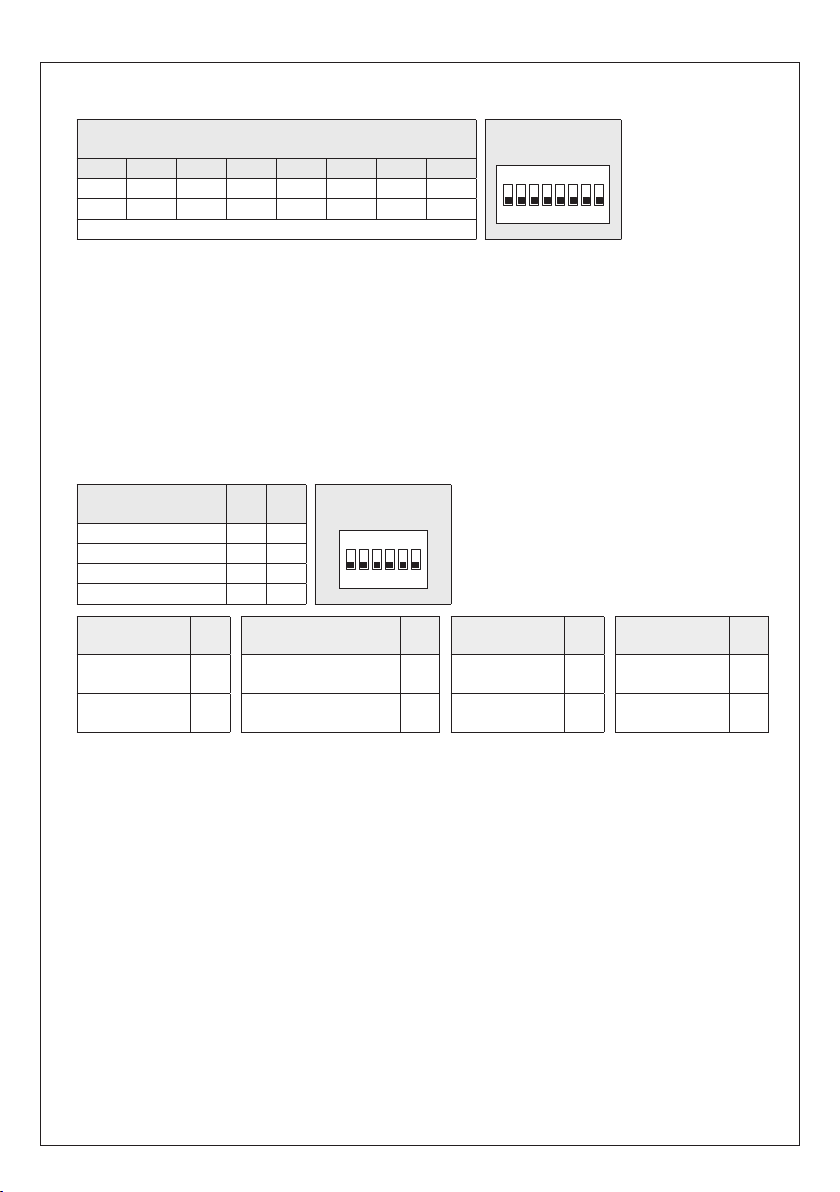
HYGRASGARD
1 2 3 4 5 6 7 8
ON DIP A
1 2 3 4 5 6
ON DIP B
r
®
RFTF - Mo dbus
| Конфигурация
АДРЕС ШИНЫ
Адрес шины
(двоичный, настраиваемая значимость от 1 до 247)
DIP 1 DIP 2 DIP 3 DIP 4 DIP 5 DIP 6 DIP 7 DIP 8
128 64 32 16 8 4 2 1
O N O N
Данн ый пр имер п оказы вает, ч то 128 + 64 + 1 = 193 — это а дрес ш ины Modbus.
Адрес прибора
Положение переключателей, поз. от 1 до 8— см. таблицу на обратной стороне!
Адрес 0 зар езервирован д ля сообщений се ти; запрещ ается опреде лят ь адреса больш е 247; прибор буде т игнорировать их.
DIP-переключатели имеют двоичное кодирование со следующей значимостью:
DIP 1 =
128
DIP 2 =
64
DIP 3 = 32 ............ DIP 3 = OFF
DIP 4 = 16 ............ DIP 4 = OFF
DIP 5 = 8 ............ DIP 5 = OFF
DIP 6 = 4 ............ DIP 6 = OFF
DIP 7 = 2 ............ DIP 7 = OFF
DIP 8 =
OFF OFF OFF OFF OFF
в диапазоне от
............ DIP 1 = ON
............ DIP 2 = ON
1
............ DIP 8 = ON Данный пример показывает, что
1 до 247
(двоичный формат) настраивается с помощью DIP-переключателя [A].
O N
128 + 64 + 1 = 193 — это адрес шины Modbus.
MODBUS
DIP-переключатель [A
]
ПАРАМЕТРЫ ШИНЫ
Скорость передачи
(настраиваемая)
9600 бод
19200 бод
3840 0 бод
зарезервировано
DIP
DIP
1
O N
OFF
O N O N
O N
OFF
OFF OFF
2
MODBUS
DIP-переключатель [B
]
Чётность
(настраиваемая)
EVEN
(чётные)
ODD
(нечётные)
Скорость передачи данных
Можно настроить
Чётность
Можно настроить
Контроль чётности
(1стоповый бит)
Режим 8N1 вк лючается с пом ощью поз.5 DIP-перек лючате ля [B].
При этом функции поз.3 (чётность) и поз.4 (контроль чётности) DIP-переключателя [B] становятся неактивными.
Можно настроить: режим 8N1 активный или неактивный (по умолчанию)— см. таблицу!
Оконечная нагрузка шины
резистор шины 120Ом) или
В слу чае приборов с
на дисплее на протяжении прим. 30 секунд.
ИНДИКАЦИЯ СОСТОЯНИЯ СВЯЗИ
Индикация состояния связи осуществляется с помощью 2 светодиодных индикаторов. Индикация успешного получения
телеграммы производится путем загорания зеленого индикатора независимо от адреса прибора. Индикация телеграмм с
ошибками или вызванных исключительных телеграмм Modbus производится путем загорания красного индикатора.
ДИАГНОСТИКА
Функция диагностики неисправностей встроена
Контроль чётности
DIP
3
(вк л./ вык л.)
активный
O N
(1стоповый бит)
неактивный (без чётности)
OFF
(2стоповых бит а)
(в бод ах) настраивается с помощью поз. 1 и 2 DIP-переключателя [B].
9600бо д, 19200бод
настраивается с помощью поз. 3 DIP-переключателя [B].
EVEN (чётн ые)
включает ся с помощь ю поз. 4 DIP-переключателя [B]. Можно настроить: контроль чётности—
или
неактивный (2 стоповых бита)
или
ODD (нечётные)
включает ся с помощь ю поз. 6 DIP-переключателя [B]. Можно наст роить:
неактивная
дисплеем
при изменении параметров шины и ее адреса соответствующие настройки отображаются
или
38400 бод
(без оконечной нагрузки шины)– см. таблицу!
— см. таблицу!
— см. таблицу!
, т.е. контроль чёт ности от сутствует — см. таблицу!
DIP
O N
OFF
38
4
8N1-M odus
(вкл./выкл.)
активн.
неактивный
(по умолчанию)
DIP
O N
OFF неактивная OFF
Оконечная нагрузка
шины
5
активн.
активная
(вкл./выкл.)
активный
(нагрузочный
DIP
6
O N

HYGRASGARD
r
®
RFTF - Mo dbus
| Конфигурация
ИНДИКАЦИЯ НА ДИСПЛЕЕ
В стандартном исполнении в первой строке поочередно и
соответствующими единицами измерения:
температура
(°C),
относительная влажность
циклично
отображаются следующие измеренные значения с
(%). (разрешение показаний составляет 1/10°C или 1/10 % о тн. влажн.)
Используя шинный интерфейс, вместо стандартной индикации можно запрограммировать отображение альтернативной
выходной величины:
относительная влажность
При эт ом в первой строк е
Индекс обозначает тип индикации, например, температура точки росы (см. таблицу «Функция 06— Запись значения в один
регистр хранения (Write Single Register)»).
Посредством шинного интерфейса дисплей можно программировать как в 7- и 14-сегментном поле, так и в поле с точечной
матрицей. Так, например, можно отображать сообщения, получаемые от ПЛК.
Для
индивидуальной индикации
Реги стры от 4х0002 до 4х0012 сод ержат све дения об отображаемых симво лах и сегментах.
При настройке по умолчанию (регистр 4x0001 содержит значение 0) можно также запрограммировать поле с точечной
матрицей. При этом в 7-сегментном поле будут отображаться текущие измеренные значения.
Пример структуры сегментного поля (регистр 4x0005)
Бит 0 .....
Точка A
Бит 1 .....
Точка B
Бит 2 .....
Точка C
Бит 3 .....
Точка D
Бит 4 .....
Точка DP
Бит 5 .....
Процент
Бит 6 .....
- -
Бит 7 .....
- -
Бит 8 .....
- -
Бит 9 .....
- -
Бит 10 ...
- -
Бит 11 ...
- -
Бит 12 ...
- -
Бит 13 ...
- -
Бит 14 ...
- -
Бит 15 ...
- -
точка росы
(°C),
(%),
статично
соотношение компонентов смеси
температура
Значение:
Индекс:
Единица измерения:
регистр 4x0001 (физическое значение) должен содержать значение 10.
(°C) или
отображ ается значение с индексом, а во вт орой — соо тве тст вую щая е диница из мерения.
Точк а A
Точ. матрица A B C D E F G
заданное значение потенциометра
13.8
1
°C
Точк а B Точка C Точка D ПроцентТочк а DP
(г/кг),
абсолютная влажность
(%)
(г/м3),
энтальпия
14-сегментное поле 1
14-сегментное поле 2
(к Дж/кг),
Пример структуры 14-сегментного поля (регистр 4x0003 и 4x0004)
Бит 0 .....
Бит 1 .....
Бит 2 .....
Бит 3 .....
Бит 4 .....
Бит 5 .....
Бит 6 .....
Бит 7 .....
Бит 8 .....
Бит 9 .....
Бит 10 ...
Бит 11 ...
Бит 12 ...
Бит 13 ...
Бит 14 ...
Бит 15 ...
A
B
C
D
E
F
G
G'
H
I
J
K
L
M
- -
- -
A
H
F B
G G'
E C
M
I
D
L
39
J
K
Пример для символа
градуса Цельсия (°C)
14-сегментное поле 1: 14-сегментное поле 2:
227 57
(регистр 4x003) (регистр 4x004)

Символ
Пробел
!
“
#
$
%
&
(
)
*
+
,
-
.
/
0
1
2
3
4
®
RFTF - Mo dbus
ASCII
53
54
55
56
57
58
59
60
61
62
63
64
65
66
67
68
69
70
71
72
| Конфигурация, телеграммы
Символ
5
6
7
8
9
:
;
<
=
>
?
@
A
B
C
D
E
F
G
H
ASCII
73
74
75
76
77
78
79
80
81
82
83
84
85
86
87
88
89
90
91
93
Символ
M
N
O
Q
U
W
I
J
K
L
P
R
S
T
V
X
Y
Z
[
]
HYGRASGARD
r
Таблица ко дов ASCII для полей с точечной матрицей
ASCII
32
33
34
35
36
37
38
40
41
42
43
44
45
46
47
48
49
50
51
52
Неуказанные в таблице символы ASCII или управляющие символы отображаются в виде пробела.
ASCII
94
95
96
97
98
99
100
101
102
103
104
105
106
107
108
109
110
111
112
113
Символ
^
_
\
a
b
c
d
e
f
g
h
i
j
k
l
m
n
o
p
q
ASCII
114
115
116
117
118
119
120
121
122
123
124
125
129
132
142
148
153
154
223
Символ
r
s
t
u
v
w
x
y
z
{
|
}
ü
ä
Ä
ö
Ö
Ü
°
СВЕТОДИОДНЫЕ ИНДИКАТОРЫ
Отдельные светодиодные индикаторы (регистр 4x0014 = 0)
Управление цветом и яркостью светодиодов может по отдельности осуществляться через шину Modbus.
С помощью регис тров 4x0015 ... 4x0019 (Светодиод x вид, x=1…5) мож но задат ь
(горит постоянно/различные виды мигания) или присвоить кнопку присутствия светодиоду.
Через регистры 4x0020 ... 4x0024 (Светодиод x цвет, x=1...5) можн о зад ать
(см. таблицу). При этом в разряде десятков задаётся цвет, в разряде единиц - яркость. Значение 100 при присвоении цвета
и яркости у казывает на соо тве тст вующие регис тры ц вета светодиода (4x0025 ... 4x0039) с возможностью отдельного
присвоения трёх цветов красного, зелёного и синего.
Светодиодная индикация включается и выключается через телеграмму MODBUS "
Показанные настройки регистров соответствуют
следующему примеру различных рабочих сообщений и
сигналов неисправностей:
Светодиод 1 красный
Светодиод 2 жёлтый
Светодиод 3 белый
Светодиод 4 зелёный
Светодиод 5 белый
с кнопкой
Тревога – быстро мигает
Предупреждение – медленно мигает
Работа
Работа
Присутствие, включая соединение
4x0 014
4x0015
4x0016
4x0017
4x0018
4x0019
4x0020
4x0021
4x0022
4x0023
4x0024
40
состояние индикации светодиода
цвет и яркость светодиода
Function 05 Write Single Coil
= 0 (светодиоды реагируют по отдельности)
= 4 (быстрое мигание)
= 2 (среднее мигание)
= 0 (горит постоянно)
= 0 (горит постоянно)
= 5 (смена состояния кнопкой присутствия)
= 35 красный ц вет
= 25 жёл тый ц вет
= 5 белый цвет
= 55 зелёный ц вет
= 5 белый цвет
".

HYGRASGARD
r
Индикация гистограммы светодиодами (регистр 4x0014 = 1 ... 4)
Светодиоды подключены в цепь индикации и показывают цветом в регистре 4x0013 (значение гистограммы)
введённое значение. Отдельные промежуточные ступени отображаются изменением яркости.
Цвет гистограммы выбирается через регистр 4x0014 (вид гистограммы) и может при необходимости индивидуально
задаваться через регистры цвета све тод иод а (4x0025 ... 4x0039).
Показанные настройки регистров соответствуют
следующему примеру
светофорной индикации
Светодиод 1 красный (регистр цвета)
Светодиод 2 жёлтый
Светодиод 3 жёлто-зелёный
Светодиод 4 зелёный
Светодиод 5 зелёный
®
RFTF - Mo dbus
самоопределяемой
:
| Конфигурация, телеграммы
4x0013
Значение
4x0 014
= 4
4x0020
= 100 (самоопределённый красный цвет)
4x0021
= 25 жёлтый цвет
4x0022
= 45 жёл то-зелёный цвет
4x0023
= 55 зелёный цвет
4x0024
= 55 зелёный цвет
4x0025
= 40 регистр красного цвета
4x0026
= 1 регистр зелёного цвета
4x0027
= 2 регистр синего цвета
ПОТЕНЦИОМЕТР И ПОВОРОТНЫЙ ВЫКЛЮЧАТЕЛЬ
Положение потенциометра регистрируется в области 0-100% и выдаётся через регистр 3x0005 (заданное значение
потенциометра). Положение поворотного выключателя (опция) запрашивается через регистр 3x0010 (поворотный
вык лючатель) в положениях от 1 до 5.
КНОПКА ПРИСУТСТВИЯ
Кнопка присутствия отображается через регистры от 1x0001 до 1x0003. Если кнопке не присвоен светодиод
вид светодиода (LED Mode) не имеет значение 5
(
1x0001 Кнопка нажата = 1, распознавание через смену сигнала
1x0002 Кнопка отпущена = 1, распознавание через смену сигнала
1x0003 Статус кнопки, текущее состояние кнопки на момент опроса
Информация о кнопке, к оторая вызывается через смену сигнала, сохраняется до с ледующ его опроса телеграмм MODBUS
"
Function 02 Read Discrete Input
шины (например, 1 секунда).
Если кнопка присвоена светодиоду (
автоматически происходит смена состояния светодиода. Соответствующий светодиод должен быть включен через функцию
05 Write Single Coil.
Опрос состояния светодиода возможен через регистр 1x0001.
Регистр 1x0002 не задействован.
Реги стр 1x0003 показывает текущее с ост ояние кно пки на момент опр оса.
Состояние светодиода может быть дополнительно установлено или удалено через функцию 05 Write Single Coil Bit 6.
", чтобы нажатие кнопки надёжно фиксировалось в т.ч. при длительных циклах считывания
вид светодиода (LED Mode) содержит значение 5
), то состояния кнопки могут определяться через следующие регистры:
), то при каждом на жатии кнопк и
ТЕЛЕГРАММЫ
Функция 04— Чтение регистров ввода (Read Input Register)
Регистр Параметр Тип данных Значение Диапазон
3x0001
3x0002
3x0003
3x0004
3x0005
3x0006
3x0007
3x0008
3x0009
3x0010
Температура
Температура
Относительная влажность
Относительная влажность
Заданное значение потенциометра Со знаком 16би т 0...1000 0.0...100.0 %
Точка росы Расчетное значение Со знаком 16бит 0...5 00 0.0...+50.0 °C
Абсолютная влажность Расчетное значение Со знаком 16би т 0...800
Соотношение компонентов смеси
Энтальпия Расчетное значение Со знаком 16бит 0...850
Поворотный выключатель Без знака 8 бит 0...4 Полож ен иях 1...5
Считывание 4 с
Фильт рац ия 32 с
Считывание 4 с
Фильт рац ия 32 с
Расчетное значение Со знаком 16бит 0...800 0.0...80.0 г / кг
Со знаком 16бит 0...500 0.0...+50.0 °C
Со знаком 16бит 0...500 0.0...+50.0 °C
Со знаком 16бит 0...1000 0.0...100.0 %
Со знаком 16бит 0...1000 0.0...100.0 %
0.0...80.0
0.0...85.0
41
г / м
кД ж /кг
3

HYGRASGARD
r
®
RFTF - Mo dbus
| Телеграммы
Функция 06— Запись значения в один регистр хранения (Write Single Register) и функция 16—
Запись значений в несколько регистров хранения (Write Multiple Register)
Регистр Параметры (дисплей) Тип данных Значение Диапазон
4x0001
4x0002
4x0003
4x0004
4x0005
4x0006
4x0007
4x0008
4x0009
4x0010
4x 00 11
4x0012
4x0040
Физическое значение Индекс на дисплее Без знака 8 Bit 0 …10 0…10
Стандартная индикация (цикличная):
Температу ра, °C,
Относительная влажность, %
Альтернативная индикация (статичная):
Температура, °C 1 1
Заданное значение потенциометра, % 2 2
Точка ро сы, °C 3 3
Относительная влажность, % 4 4
Абсолютная влажность, г/м
Соотношение по массе, г/кг 6 6
Энтальпия, кДж /кг 7 7
Настраиваемая индикация – 10
7-сегментное значение Со знаком 16бит -999…9999 -999…9999
Пример 14-сегментного поля 1 см. рисунок Без знака 16бит
Пример 14-сегментного поля 2 см. рисунок Без знака 16бит
Пример сегментного поля Без знак а 16бит
Точечная матрица, символА Б ез зна ка 8бит 0…255 Симв ол ASCII
Точечная матрица, символВ Б ез зна ка 8бит 0…255 Симв ол ASCII
Точечная матрица, символС Б ез зна ка 8бит 0…255 Симв ол ASCII
Точечная матрица, символD Бе з знак а 8бит 0…255 Симво л ASCII
Точечная матрица, символЕ Без знака 8бит 0…255 Символ ASCII
Точечная матрица, символF Без знака 8бит 0…255 Символ ASCII
Точечная матрица, символG Без знака 8бит 0…255 Символ ASCII
Яркость подсветки ЖК-дисплея Без знака 8 Bit 0...63 0...100%
3
– 0
5 5
Наст ройка по
умолчанию
см. битовую омбинацию
см. битовую омбинацию
см. битовую омбинацию
Регистр Параметры (светодиоды) Тип данных Значение Диапазон
4x0013
4x0 014
4x0015
4x0016
4x0017
4x0018
4x0019
Значение гистограммы (светодиод) Без знака 16би т 0…1000 0…1000
Вид гистограммы Без знака 8би т 0…4
Независимо управляемые светодиоды 0
Гистограмма А
Гистограмма В
Гистограмма С
Гистограмма D
Свет одиод 1 ви д Без знака 8б ит 0…5 Default = 0
Свет одиод 2 ви д Без знака 8б ит 0…5 Default = 0
Свет одиод 3 ви д Без знака 8б ит 0…5 Default = 0
Свет одиод 1 ви д Без знака 8б ит 0…5 Default = 0
Свет одиод 5 ви д Без знака 8б ит 0…5 Default = 0
Постоянно горит 0
Короткое мигание 1
Среднее мигание 2
Длинное мигание 3
Быстрое мигание 4
Смена кнопкой 5
Зелёный - Зелёный - Жёлтый - Жёлтый Красный
(светофорный светодиод)
Зелёный - Жёлтый - Красный
(все светодиоды одинакового цвета)
Синий - Красно-синий - Красный
(все светодиоды одинакового цвета)
Цвет из
регистра цвета светодиода
42
Настройка по умолчанию
1
2
3
4
Настройка по умолчанию

HYGRASGARD
r
®
RFTF - Mo dbus
| Телеграммы
Функция 06— Запись значения в один регистр хранения (Write Single Register) и функция 16—
Запись значений в несколько регистров хранения (Write Multiple Register)
Регистр Параметры (светодиоды) Тип данных Значение Диапазон
4x0020
4x0021
4x0022
4x0023
4x0024
4x0025
4x0026
4x0027
4x0028
4x0029
4x0030
4x0031
4x0032
4x0033
4x0034
4x0035
4x0036
4x0037
4x0038
4x0039
Свет одиод 1 цв ет Б ез знака 8бит 0 …100 Default = 0
Свет одиод 2 цв ет Б ез знака 8бит 0 …100 Default = 0
Свет одиод 3 цв ет Б ез знака 8бит 0 …100 Default = 0
Свет одиод 4 цв ет Б ез знака 8бит 0 …100 Default = 0
Свет одиод 5 цв ет Б ез знака 8бит 0 …100 Default = 0
Белый 0…9
Жёлтый 10…1 9
Оранжевый 20…29
Красный 30…39
Жёлто-зелёный 40…49
Зелёный 50…59
Бирюзовый 60…69
Синий 70…79
Фиолетовый 80…89
Регистр цвета
Свет одиод 1 регистр цвета Красный 0…63
Свет одиод 1 регистр цвета Зелёный 0…63
Свет одиод 1 регистр цвета Синий 0…63
Свет одиод 2 регистр цвета Красный 0…63
Свет одиод 2 регистр цвета Зелёный 0…63
Свет одиод 2 регистр цвета Синий 0…63
Свет одиод 3 регистр цвета Красный 0…63
Свет одиод 3 регистр цвета Зелёный 0…63
Свет одиод 3 регистр цвета Синий 0…63
Свет одиод 4 регистр цвета Красный 0…63
Свет одиод 4 регистр цвета Зелёный 0…63
Свет одиод 4 регистр цвета Синий 0…63
Свет одиод 5 регистр цвета Красный 0…63
Свет одиод 5 регистр цвета Зелёный 0…63
Свет одиод 5 регистр цвета Синий 0…63
100
тёмный = 0
яркий = 9
тёмный = 10
яркий = 19
тёмный = 20
яркий = 29
тёмный = 30
яркий = 39
тёмный = 40
яркий = 49
тёмный = 50
яркий = 19
тёмный = 60
яркий = 69
тёмный = 70
яркий = 79
тёмный = 80
яркий = 89
43
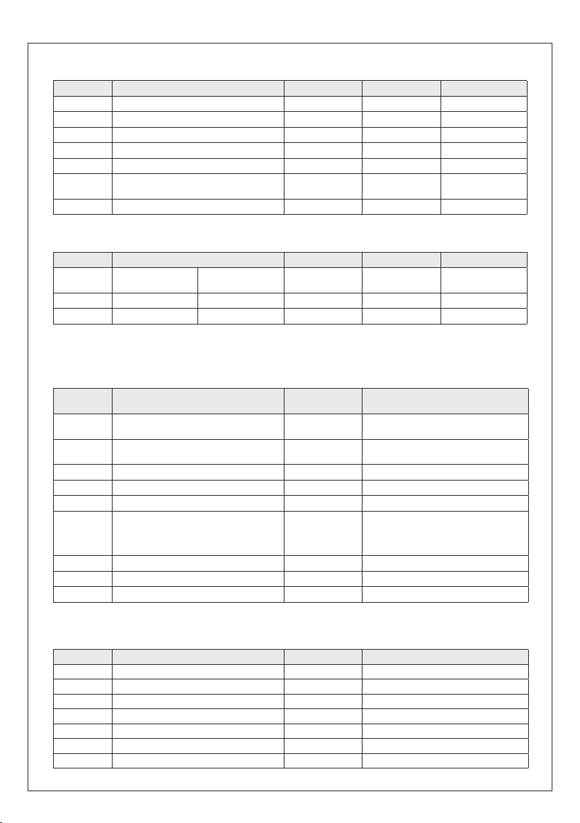
HYGRASGARD
r
®
RFTF - Mo dbus
| Телеграммы
Функция 05— Запись значения одного флага (Write Single Coil)
Регистр Параметр Тип данных Значение Диапазон
0x0001
0x0002
0x0003
0x0004
0x0005
0x0006
0x0007
Многоцветный светодиод 1 Бит 0 0 / 1 OFF - ON
Многоцветный светодиод 2 Бит 1 0 / 1 OFF - ON
Многоцветный светодиод 3 Бит 2 0 / 1 OFF - ON
Многоцветный светодиод 5 Бит 3 0 / 1 OFF - ON
Многоцветный светодиод 6 Бит 4 0 / 1 OFF - ON
Set / Clear
светодиод состояния кнопки
Яркость подсветки ЖК-дисплея Би т 6 0 / 1 OFF - ON
Бит 5 0 / 1 CLE AR - SET
Функция 02— Чтение значений из нескольких дискретных входов (Read Discrete Input)
Регистр Параметр Тип данных Значение Диапазон
1x0001
1x0002
1x0003
Примечание: адреса от 1x0003 до 1x0008 читаются со значением "0".
Функция 08— Диагностика (Diagnostics)
Под держиваютс я
Код
подфункции
00
01
04
10
11
12
13
14
15
Кнопка присутствия /
статус светодиода
Кнопка присутствия отпущена Бит 1 0 / 1 OFF - ON
Кнопка присутствия текущее Б ит 2 0 / 1 OFF - ON
следующие коды подфункции
Параметр Тип данных Ответ
Эхо отправленных данных
(Loopback)
Перезапуск Modbus
(Reset Listen Only Mode)
Акт ивация Listen Only Mode Без ответа
Сброс счетчиков Телеграмма эхо
Счетчик телеграмм шины Бе з знак а 16бит Все действительные телеграммы шины
Счетчик ошибок связи
(четность, циклическая проверка четность
с избыточностью (CRC),
ошибка фрейма и т.д.)
Счетчик исключительных сообщений Без знака 16бит Счетчик ошибок
Счетчик телеграмм ведомого устройства Без знака 16бит Телеграммы ведомого устройства
Счетчик телеграмм без ответа Без знака 16би т Сообщения сети (адрес 0)
нажата /
установлен
Бит 0 0 / 1 OFF - ON
Данные эхо
Телеграмма эхо
Без знака 16бит Телеграммы шины с ошибками
Функция 17— Чтение информации об устройстве (Report Slave ID)
Структура телеграммы ответа
Бит № Параметр Тип данных Ответ
00
01
02
03
04
05
06
Количество байт Без зн ака 8бит 6
Идентификатор ведомого устройства (тип устройства)
Идентификатор ведомого устройства (класс устройства)
Состояние Без знака 8бит 255 = RUN, 0 = ST OP
Номер версии (выпуск) Без знака 8би т 1… 9
Номер версии (версия) Без знака 8бит 1…99
Номер версии (индекс) Без знака 8бит 1
Без знака 8би т 11 =
Без знака 8би т 20 =
44
HYGRASGARD® MODBUS
HYGRASGARD® /
HYGRASREG
®

AERASGARD
r
Общая структ ура шины
®
RFTF - Mo dbus
| Подключение
MODBUS
RTU-Master
Пассивное
ответвление
LA LA
Оконечная
нагрузка
шины
Тупиковая
линия
(ответвительный кабель)
Slave 1 Slave 2
Магистральная конфигурация с нагрузочными резисторами и резисторами в цепи смещения
Оконечная
нагрузка
шины
Активное
ответвление
MODBUS
RTU-Master
Магистральная
линия
(магистральный
кабель)
Тупикова я
линия:
короче 20 м
A (D1) D+
B (D0) D–
RS-485
Slave n
Многократное
ответвление n:
короче 40 м/n
5 B
Подтягивающий резистор /
резистор в цепи смещения
Стягивающий резистор /
резистор в цепи смещения
Оконечная
нагрузка
шины
Оконечная
нагрузка
шины
Общее
заземление
Slave 1 Slave 2
Нагрузочные резисторы должны устанавливаться только на концах шины.
В сетях без повторителей разрешается использовать не больше двух оконечных нагрузок шины.
С помощью DIP-переключателя 6 можно активировать оконечную нагрузку шины на приборе. Резисторы в цепи смещения
для определения уровня шины в состоянии покоя обычно активируются на главном устройстве Modbus/повторителе.
Максимальное количество абонентов на один сегмент Modbus составляет 32 прибора.
В случае большего количества абонентов следует разделить шину с помощью повторителей на несколько сегментов.
Адреса абонен тов м ожно настраивать от 1 до 247.
Для линии шины следует использовать кабель с парной скруткой/электропитанием и медным экраном.
Емкость линии на единицу длины должна составлять при этом меньше 100пФ/м (напр., линия Profibus).
45
(GND)

Монтаж и ввод в эксплуатацию
r
Приборы следует устанавливать в обесточенном состоянии. Подключение должно осуществляться исключительно к безопасно малому
напряжению. Повреждения приборов вследствие несоблюдения упо
мянутых требований не подлежат устранению по гарантии; ответственность производителя исключается. Монтаж и ввод в эксплуатацию должны осуществляться только специалистами. Действительны
исключительно технические данные и условия подключения, приве
денные на поставляемых с приборами этикетках ⁄ табличках и в руководствах по монтажу и эксплуатации. Отклонения от представленных
в каталогехарактеристик дополнительно не указываются, несмотря
на их во зможнос ть в си лу те хнич еского прогресса и по сто янно го со
вершенствования нашей продукции. В случае модификации приборов
потребителем гарантийные обязательстватеряют силу. Эксплуатация
вблизи оборудования, не соответствующего нормам электромагнит
ной совместимости (EMV), может влиять на работу приборов. Недопустимо использование данного прибора в качестве устройства
контроля ⁄ наблюдения, служащего исключительно для защиты лю
дей от травм и угрозы для зд оров ья ⁄ жизни, а также в качестве
аварийного выключателя устройств и машин или для аналогичных
задач обеспечения безопасности.
Размеры корпусов и корпусных принадлежностей могут в определён
ных преде лах отличаться от указанных в д анном рук оводстве.
Изменение документации не допускается.
В случае рекламаций принимаются исключительно цельные приборы
в оригинальной упаковке.
Указания к продуктам
r
В качестве Общих Коммерческих Условий имеют силу исключительно наши Условия, а также действительные «Общие условия поставки
дукции и услу г для электрической промышленности» (ZVEI) вклю чая дополните льную статью «Расширенное сохранение прав собственности».
Помимо этого, следует учитывать следующие положения:
– Перед установкой и вводом в эксплуатацию следует прочитать данное руководство; должны быть учтены все приведенные в нем указания!
– Подключение прибора должно осуществляться исключительно к безопасно малому напряжению и в обесточенном состоянии.
Во избежание повреждений и отказов (например, вследствие наводок) следует использовать экранированную проводку,
избегать параллельной прокладки токоведущих линий и учитывать предписания по электромагнитной совместимости.
– Данный прибор следует применять только по прямому назначению, учитывая при этом соответствующие предписания VDE
(союза немецких электротехников), требования, действующие в Вашей стране, инструкции органов технического надзора и местных
органов энергоснабжения. Надлежит придерживаться требований строительных норм и правил, а также техники безопасности и
избегать угроз безопасности любого рода.
– Мы не несем ответственности за ущерб и повреждения, возникающие вследствие неправильного применения наших устройств.
– Ущерб, возникший вследствие неправильной работы прибора, не подлежит устранению по гарантии.
– Монтаж и ввод в эксплуатацию должны осуществляться только специалистами.
– Действительны исключительно технические данные и условия подключения, приведенные в поставляемых с приборами руководствах по
монтажу и эксплуатации. Отклонения от представленных в каталоге характеристик дополнительно не указываются,
несмотря на их возможность в силу технического прогресса и постоянного совершенствования нашей продукции.
– В случае модификации приборов потребителем гарантийные обязательства теряют силу.
– Не разрешается использование прибора в непосредственной близости от источников тепла (например, радиаторов отопления)
или создаваемых ими тепловых потоков; следует в обязательном порядке избегать попадания прямых солнечных лучей или теплового
излучения от аналогичных источников (мощные осветительные приборы, галогенные излучатели).
– Эксплуатация вблизи оборудования, не соответствующего нормам электромагнитной совместимости (EMV), может влиять на работу приборов.
– Недопустимо использование данного прибора в качестве устройства контроля ⁄ наблюдения, служащего для защиты людей от травм
и угрозы для здоровья ⁄ жизни, а также в качестве аварийного выключателя ус тройств и машин или д ля аналог ичных зад ач обеспечения
безопасности.
– Размеры корпусов и корпусных принадлежностей могут в определённых пределах отличаться от указанных в данном руководстве.
– Изменение документации не допускается.
– В случае рекламаций принимаются исключительно цельные приборы в оригинальной упаковке.
Ввод в эксплуатацию обязателен и выполняется только специалистами! Перед монтажом и вводом в эксплуатацию
прочитать данное руководство; должны быть учтены все приведенные в нем указания!
Указания к механическому монтажу:
Монтаж должен осуществляться с учетом соответствующих,
действительных для места измерения предписаний и стандартов
(напр., предписаний для сварочных работ). В особенности следует
принимать во внимание:
– указа ния VDE ⁄ VDI (союз немецк их электрот ехников ⁄ союз
немецких инженеров) к техническим измерениям температуры,
-
директивы по устройствам измерения температуры
– директивы по электромагнитной совместимости
(их следует придерживаться)
– непременно следует избегать параллельной прокладки
токоведущих линий
– рекомендуется применять экранированную проводку; экран следует
при эт ом с од ной стороны мон тировать к DDC ⁄ PLC.
-
Монтаж следует осуществлять с учетом соответствия прилагаемых
технических параметров термометра реальным условиям
эксплуатации, в особенности:
-
– диапазона измерения
– максимально допустимого давления и скорости потока
– установочной длины, размера трубки
– допустим ых ко леба ний, ви брац ий, ударов ( д.б. < 0,5 g).
-
Указания по вводу в эксплуатацию:
Этот прибор был откалиброван, отъюстирован и проверен в стандартных
условиях. Во время эксплуатации в других условиях рекомендуется
провести ручн ую юс тировку на месте в первый раз при вводе в
эксплуатацию и затем на регулярной основе.
46
про-

D G F r
HYGRASGARD
Gehäuse
Housing
Boîtier
Корпус
®
RFTF - Modbus
Baldur
Zum Öffnen des Gehäuses einen Schraubendreher (2,0) in die Nut
mittig ansetzen, nach unten drücken und den Bodenrahmen etwas
anheben. Den Deckel nach vorne ziehen und halten.
To open the housing, set a screwdriver (2.0) in the groove at centre,
press down, and lift up the bott om frame slightly. Pull top cover
forward and hold it.
Pour ou vrir le boîtier placer le tournevis (2,0) au centr e de l’encoche,
pousser vers le bas et soulever légèrement le cadre inférieur. Tirer le
couvercle vers l’avant et le maintenir.
Чтобы открыть корпус, вставьте жало отвертки (2,0) в паз
по центру, надавите вниз и слегка приподнимите основание
корпуса. Крышку сдвигайте вперед, аккуратно удерживая ее.
©
Copyright by
Nachdruck, auch ausz ugsweise, nur mit Genehmigung der S +S Regeltechnik GmbH.
Reprin t in full or in part s requires permission f rom S+ S Regelt echnik GmbH.
La reproduction des t extes même partielle est uniquement a utorisée apr ès acco rd de la société S+S Regeltechnik GmbH.
Перепечатка, в том чис ле в сокращ енно м вид е, разр ешае тся лишь с согласия S+S Regeltechnik GmbH.
Irrtümer und technische Änderungen vorbehalten. Alle Angaben entsprechen unserem Kenntnisstand bei Veröffentlichung. Sie dienen nur zur Information über
unsere Produkte und deren Anwendungsmöglichkeiten, bieten jedoch keine Gewähr für bestimmte Produkteigenschaften. Da die Geräte unter verschiedensten
Bedingungen und Belastungen eingesetzt werden, die sich unserer Kontrolle entziehen, muss ihre spezifische Eignung vom jeweiligen Käufer bzw. Anwender selbst
geprüft werden. Bestehende Schutzrechte sind zu berücksichtigen. Einwandfreie Qualität gewährleisten wir im Rahmen unserer Allgemeinen Lieferbedingungen.
Subjec t to err ors and t echnical changes. All statem ents and data herein represent our best knowledge a t date of publica tion. They are o nly meant to inf orm about
our pro ducts and their applica tion po tential, but do not imply a ny warranty as to cer tain pr oduct charac teris tics. Sin ce the devices are used under a wide range
of differen t conditions and loads beyond our contr ol, their particular suitabili ty must be verif ied by each cust omer and/or end user the mselves. Exist ing propert y
rights must be observed. We warrant the faultless quality of ou r produ cts as stated in our General Terms and Condi tions.
Sous réserve d'erreurs et de modific ations techniques. Toutes les informat ions correspondent à l'état de n os connaissanc es au moment de la publication. Elles
servent uniquement à informer sur nos produits et leurs possibilités d'application, mais n'offrent aucune garantie pour certaines caractéristiques du produit. Etant
donné que les appareils sont soumis à des conditions et des sollicitat ions div erses qui sont ho rs de notre con trôle, leur adéquatio n spécif ique doit être v érifiée
par l'ach eteur o u l'utilisateu r respectif. Tenir compte des droits de propriété existants. Nous garan tissons une quali té par faite dans le cadre de nos condit ions
générales de livraison.
Возможны ошибки и технические изменения. Все данные соответствуют нашему уровню знаний на момент издания. Они представляют собой информацию о
наших изделиях и их возможностях применения, однако они не гарантируют наличие определенных характеристик. Поскольку устройства используются при
самых различных условиях и нагрузках, которые мы не можем контролировать, покупатель или пользовате ль должен сам проверить их пригодность. Соблюдать
действующие права на промышленную собственность. Мы гарантируем безупречное качество в рамках наших «Общих условий поставки».
S+S Regeltechnik GmbH
47

D G F r
Busadresse, binärcodiert
Bus address, binary coded
Adresse du bus, code binaire
Адресс шины, двоичный
1 00000001
2 00000010
3 00000011
4 00000100
5 00000101
6 00000110
7 00000111
8 00001000
9 00001001
10 00001010
11 00001011
12 00001100
13 00001101
14 00001110
15 00001111
16 00010000
17 00010001
18 00010010
19 00010011
20 00010100
21 00010101
22 00010110
23 00010111
24 00011000
25 00011001
26 00011010
27 00011011
28 00011100
29 00011101
30 00011110
31 00011111
32 00100000
33 00100001
34 00100010
35 00100011
36 00100100
37 00100101
38 00100110
39 00100111
40 00101000
41 00101001
42 00101010
43 00101011
44 00101100
45 00101101
46 00101110
47 00101111
48 00110000
49 00110001
50 00110010
51 00110011
52 00110100
53 00110101
54 00110110
55 00110111
56 00111000
57 00111001
58 00111010
59 00111011
60 00111100
61 00111101
62 00111110
63 00111111
64 01000000
65 01000001
66 01000010
67 01000011
68 01000100
69 01000101
70 01000110
71 01000111
72 01001000
73 01001001
74 01001010
75 01001011
76 01001100
77 01001101
78 01001110
79 01001111
80 01010000
81 01010001
82 01010010
83 01010011
84 01010100
85 01010101
86 01010110
87 01010111
88 01011000
89 01011001
90 01011010
91 01011011
92 01011100
93 01011101
94 01011110
95 01011111
96 01100000
97 01100001
98 01100010
99 01100011
100 01100100
101 01100101
102 01100110
103 01100111
104 01101000
105 01101001
106 01101010
107 01101011
108 01101100
109 01101101
110 01101110
111 01101111
112 01110000
113 01110001
114 01110010
115 01110011
116 01110100
117 01110101
118 01110110
119 01110111
120 01111000
121 01111001
122 01111010
123 01111011
124 01111100
125 01111101
126 01111110
127 01111111
128 10000000
129 10000001
130 10000010
131 10000011
132 10000100
133 10000101
134 10000110
135 10000111
136 10001000
137 10001001
138 10001010
139 10001011
140 10001100
141 10001101
142 10001110
143 10001111
144 10010000
145 10010001
146 10010010
147 10010011
148 10010100
149 10010101
150 10010110
48
151 10010111
152 10011000
153 10011001
154 10011010
155 10011011
156 10011100
157 10011101
158 10011110
159 10011111
160 10100000
161 10100001
162 10100010
163 10100011
164 10100100
165 10100101
166 10100110
167 10100111
168 10101000
169 10101001
170 10101010
171 10101011
172 10101100
173 10101101
174 10101110
175 10101111
176 10110000
177 10110001
178 10110010
179 10110011
180 10110100
181 10110101
182 10110110
183 10110111
184 10111000
185 10111001
186 10111010
187 10111011
188 10111100
189 10111101
190 10111110
191 10111111
192 11000000
193 11000001
194 11000010
195 11000011
196 11000100
197 11000101
198 11000110
199 11000111
200 11001000
201 11001001
202 11001010
203 11001011
204 11001100
205 11001101
206 11001110
207 11001111
208 11010000
209 11010001
210 11010010
211 11010011
212 11010100
213 11010101
214 11010110
215 11010111
216 11011000
217 11011001
218 11011010
219 11011011
220 11011100
221 11011101
222 11011110
223 11011111
224 11100000
225 11100001
226 11100010
227 11100011
228 11100100
229 11100101
230 11100110
231 11100111
232 11101000
233 11101001
234 11101010
235 11101011
236 11101100
237 11101101
238 11101110
239 11101111
240 11110000
241 11110001
242 11110010
243 11110011
244 11110100
245 11110101
246 11110110
247 11110111
 Loading...