

S+S Regeltechnik AERASGARD RCO2-W, AERASGARD RLQ-CO2-W, AERASGARD RFTM-LQ-CO2-W, AERASGARD RTM-CO2-SD User Manual

AERASGARD® RCO2 - W ⁄ RLQ - CO2 - W ⁄ RFTM - LQ - CO2 - W ⁄ RTM - CO2 - SD
G
®
The maintenance-free microprocessor-controlled room sensor
CO
content of th e air wit hin a range of 0...2000 ppm and the temp erature within a range of 0...+50°C. The measured values are convert ed into
2
stand ard signals of 0 -10 V.
The maintenance-free microprocessor-controlled room sensor
(can be deacti vated via DIP sw itch es)
qualit y (VOC) in one of t hree sensiti vity levels that can b e selected LOW / ME DIUM (default ) / HIGH, tem perature within a range of 0...+50°C as well as
relative humidity of 0...100 % r.H. The measured values are c onverted into standar d signals of 0 -10 V oder 4...20 m A (selectable via DIP switches). As an
option, the measured values can be shown continuously in the illuminated display.
Elegant enclosure mad e of plastic, wit h snap- on lid, base with 4-hole attachmen t, for installation on vertically or horizontally inst alled in-wall flush boxes,
with predet ermined breaking point for on-wall cable entry.
The relative humidity (% r.H.) quotient of water v apour p artial pressure divided by the sat urat ion vapour pressure a t the respect ive gas t emperature.
A digital, long-t erm st able sensor used as measu ring element for relative air humidity and temperature guarantees exact measure ment results. The air
qualit y is determined based on a (VOC) gas mixture sensor. The CO
technology).
is used fo r detecting the over all roo m climat e. It measures CO2 within a range of 0...2000 ppm o r 0...5000 ppm, air
AERASGARD
AERASGARD® R FTM - LQ - CO2 - W and
RTM - CO2 - SD with au toma tic
content of th e air is measured using an optical NDIR senso r (non-dispersive infra-red
2
calibration (fixed)
RCO2 - W / RLQ - CO2 - W
Rev. 2018 - V27 GB
is used fo r detecting the
with automatic calibration
TECHNICAL DATA
Voltage supply: 24 V AC ⁄ DC (± 10 %)
Power consumption:
Outputs:
Relay outpu t:
HUMIDITY
Sensors:
Measur ing ran ge, humid ity: 0...100 % r. H.
Opera ting range, humidity: 0...95 % r. H. (without d ew for matio n)
Deviation, humidity: typic ally
Outpu t, humi dity: 0 -10 V
TEMPERATURE
Measur ing ran ge, temp eratu re: 0...+ 50 °C
Opera ting ra nge, tem perat ure: 0...+ 50 °C
Temperat ure de viatio n: ± 0.2 K at +2 5 °C
Output, temperature:
AIR QUALITY (VOC)
Sensor, VOC : VOC sensor (metal oxide) (VOC = volatile orga nic compounds),
Measur ing range, VOC : 0...100 % air q uality; referred to calibrating gas;
Outpu t, VOC : 0 -10 V (0 V = clea n air, 10 V = pollute d air)
Measur ing accuracy, VO C : ± 20 % of final value (referred to calibrating gas)
Service life: > 60 months (under normal load condit ions)
CARBON DIOXIDE
Sensor, CO2: optical NDIR s ensor (non-dispersive inf ra-red technology),
Measuring range, CO2:
Output, CO
Measur ing accuracy, CO
Temperature dependence, CO
(CO2)
:
2
: ± 30 ppm ± 3 % of me asured value
2
RCO2 - W ⁄ RTM - CO2 - SD :
< 1.5 W ⁄ 24 V DC t ypical; < 2.9 VA ⁄ 24 V AC typical; peak curr ent 20 0 mA
RLQ - CO2 - W ⁄ RFT M - LQ - CO2 - W :
< 4.4 W ⁄ 24 V DC typical; < 6.4 VA ⁄ 24 V AC typical; peak curr ent 200 mA
RTM - CO2 - SD
Rxx - CO2 - W 0 -10 V or 4...20 mA, working r esistan ce < 800 Ω
(selectable v ia DIP switches, select ed variant applies for all outputs),
with off set po tentiomet er (± 10 % of the measu ring range)
RTM - CO2 - SD
Rxx - CO2 - W
(assign ment selecta ble via DIP switches, switchpoint adjustable)
digital humidity sensor with integrated temperature sensor,
low hysteresis, high long-term stability
± 2.0 %
or
4...20 mA (select able via DIP switches)
RTM - CO2 - SD
Rxx - CO2 - W 0 -10 V or 4...20 mA (selectable via DIP swit ches)
with ma nual calibrat ion (via zero button) and
with au toma tic calibration (can be deactivat ed via DIP switches)
multi-range switching
VOC sensitivity low, medium, high
(selectable v ia DIP switches, switchpoin t can be adjusted from 0...100 % of the output signal)
with ma nual calibrat ion (via zero button),
RTM - CO2 - SD
Rxx - CO2 - W
RTM - CO2 - SD
Rxx - CO2 - W
RTM - CO2 - SD
Rxx - CO2 - W 0 -10 V or 4...20 mA (selectable via DIP swit ches)
: ± 5 p pm ⁄ °C or ± 0 .5 % of mea sured v alue ⁄ °C
2
(whichever is higher) (continued on next page!)
0 -10 V ( fixed)
without changeover contact
with potential-free
(20...80 % r. H.) at +25 °C, o ther wise ± 3.0 %
0 -10 V ( fixed)
(selectable v ia DIP switches)
with automatic calibration (fixed)
with au toma tic calibration (can be deactivat ed via DIP switches)
0...20 00 pp m (f ixed )
0...20 00 pp m or 0...5000 ppm (select able via DIP swit ches)
0 -10 V ( fixed)
changeover contact
or
4...2 0 mA
10
(24 V / 1 A)

AERASGARD® RCO2 - W ⁄ RLQ - CO2 - W ⁄ RFTM - LQ - CO2 - W ⁄ RTM - CO2 - SD
G
Rev. 2018 - V27 GB
TECHNICAL DATA
Press ure dep endenc e: ± 0.13 % ⁄ mm Hg
Long-term stability: < 2 % in 15 years
Gas exchange: by diffusion
Ambie nt temp eratu re: 0...+ 50 °C
Warm up time: approx. 1 hour
Response time: < 2 minutes
Electrical connection: 0.14 - 1.5 mm
Enclosure: plastic, material ABS, colour pure white (similar to R AL 9010)
Dimensi ons: 98 x 98 x 33 mm (Ba ldur 2)
Installation: wall mounting or on in-wall flush box, Ø 55 mm, base with 4 holes,
Prot ection class: III (acc ording to EN 60 730)
Prot ection type: IP 30 (ac cording to EN 60 529)
Standards: CE conf ormity, elect romagnetic compa tibility according t o EN 61 326,
Optional:
AERASGARD® RT M - CO2 - SD
AERASGARD® RCO2 - W
AERASGARD® RLQ - CO2 - W
AERASGARD® RFTM - CO2 - W
(continued)
2
, via screw terminals
for at tachment to vertically or horizontally installed in-wall flush boxes for rear cable entry,
with predet ermined breaking point for cable en try f rom top ⁄ bottom in case of plain on-wall installation
EMC Directiv e 2014 ⁄ 30 ⁄ EU, Lo w Voltage Directive 2014 ⁄ 35 ⁄ EU
display with illumination,
actual humidity, actual temp erat ure, air quality and / or the actual CO
two li ne, cut out app rox. 36 x 15 mm ( W x H), for displaying
content
2
Room temperature and CO2 sensor, Standard
Room CO2 sensor, Premium
Room air quality (VOC) and CO2 sensor, Premium
Multifunctional room sensor
for humidity, temperature and CO2 content, Del uxe
AERASGARD® RF TM - LQ - CO2 - W
Multifunctional room sensor
for humidity, temperature, CO2 content and air quality (VOC), D eluxe
Type ⁄ WG02 Measuring Range
RT M - CO2 - SD
RTM-CO2-SD-U – 0...+5 0 °C 0...20 00 pp m –
RCO2 - W
RCO2-W
(without Display)
RCO2- W-D IS PL AY – – 0...2000 ⁄ 50 00 ppm – W ■ 1501-61B0-7321-200
RLQ - CO2 - W
RLQ-CO2-W – – 0...2000 ⁄ 50 00 ppm 0...100 % W 1501-61B1-7301-200
RLQ-CO2-W DISPLAY – – 0...20 00 ⁄ 5000 p pm 0...100 % W ■ 1501-61B1-7321-200
RFTM - C O2 - W
RFTM-CO2-W 0...100 % r.H. 0...+50 °C 0...2000 ⁄ 50 00 ppm – W 1501-61B6-7301-200
RFTM-CO2-W DISP LAY 0...100 % r.H. 0...+50 ° C 0...2000 ⁄ 500 0 ppm – W ■ 1501-61B6-7321-200
RFTM - L Q - CO2 - W
RFTM-LQ-CO2-W 0...100 % r.H. 0...+ 50 °C 0...200 0 ⁄ 5000 pp m 0...100 % W 1501-61B8-7301-200
RFTM-LQ-CO2-W
Outputs:
Equipment:
Not e:
Humidity Temperature CO
– – 0...2000 ⁄ 50 00 ppm – W
DIS PL AY
0...100 % r.H. 0...+50 °C 0...2000 ⁄ 50 00 ppm 0...100 % W ■ 1501-61B8-7321-200
0 -10 V or 4. ..20 mA
Standard room sensor
W = changeover contact
This unit
(selectable via DIP swi tches, select ed variant applies for all outputs) –
must not
be used as safet y-relevant device!
2
(fixed)
(switchable)
(switchable)
(switchable)
(switchable)
RTM - CO2 - SD
– Standard room sensor
with fixed output 0 -10 V!
11
RT M - CO2 - SD
Equipment
VOC Display
without changeover contact !
Item No.
(Baldur 2)
–
1501-61B2-1001-200
see
RCO2-W ⁄ RCO2-SD

AERASGARD® RCO2 - W ⁄ RLQ - CO2 - W ⁄ RFTM - LQ - CO2 - W ⁄ RTM - CO2 - SD
G
Rev. 2018 - V27 GB
Schematic diagram
²
+UB 24V AC/DC
–UB GND
Output CO
in ppm
1 2 3
Outputs
air quality (VOC)
temperature in °C
humidity in % r.H.
121113
SET REL.
NC
NO
COM
NC = Normally Closed
COM = Common
NO = Normally Open
DIP switches (Baldur 2)
DIP
ON
4
5
123 456 789
6
VOC CO² Mode
relay
switch
point
ON ON
OFFSET
r.H.°C
RFTM - L Q - CO2 - W
VOC
Plug for
sensor
display
Reset
button
VOC VOC
CO² CO²
ZERO
RFTM - L Q - CO2 - W
VOC sensitivity DIP 1 DIP 2
LOW OFF OFF
O N
MEDIUM (default)
HIGH OFF
automatic zero point DIP 3
VOC
OFF
O N
deactivated OFF
activated (default)
content DIP 4
CO
2
O N
0...2000 ppm (default) OFF
0...5000 ppm
automatic zero point DIP 6
CO
2
O N
deactivated OFF
activated (default)
O N
Relay assignment DIP 7 DIP 8
CO2 (default): 600...1900 ppm / 900...4700 ppm OFF OFF
O N
VOC: 10...95 %
Temperature: +5...+4 8 °C OFF
Humidity: 10...95% r.H.
OFF
O N
O N O N
Output DIP 9
Voltage 0 -10 V (default) OFF
Cur ren t 4...2 0 mA
Note:
DIP 5
is not assigned!
O N
Schematic diagram
²
+UB 24V AC/DC
–UB GND
Output CO
1 2 3
Outputs
temperature in °C
free
in ppm
free
RTM - CO2 - S D
4
5
6
Reset
button
CO²
ZERO
12
Mounting and Installation
G
ATTENTION!
The minimum CO
MR = 0...5000 pp m)
to the concentration and the flow velocity of the air surr ounding the sensor, the reaction of the device to the change of concentration may take
place with a delay. It is essential to choose an installation location for t he device in which t he air st ream f lows around t he sensor. Otherwise the
gas exchange may be considerably delayed or prevented.
Automatic calibration of the carbon dioxide measurement – ABC logic (default)
The automatic background logic is a self-calibrating mechanism that is suitable for use in applications in which the CO2 concentration drops to f resh
air level (350 - 400 ppm) at least three times in 7 days. This should t ypically occur during times in w hich rooms are unoccupied. T he sensor reaches
its nor mal accuracy after 24 hours of continuous operation in an envir onment that has been subjected to a fresh air supply of 4 00 ppm CO
deviation errors remain minimal if the sensor is exposed to fresh air at least 4 times within 21 days. The ABC logic needs continuous oper ating
cycles of more than 24 hours to operate correctly.
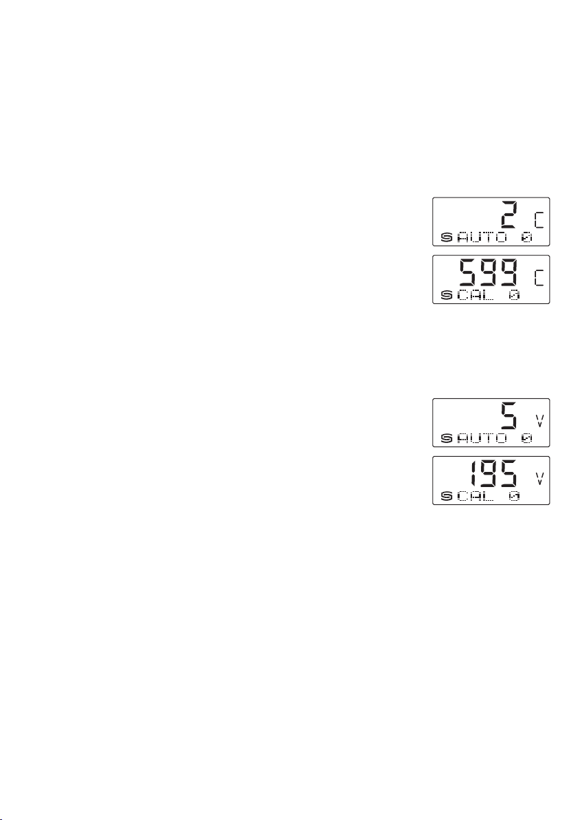
Manual calibration of carbon dioxide measurement
Manual calibration can be carried out independently of the DIP switch position (ABC logic).
Sufficient fresh air (CO2 content = 500 ppm) must be provided before and after the calibration procedure!
The calibration procedur e is started by pressing the “
This is signalled by t he flashing LED or the countdown timer on the display (
Then calibration takes place.
During t his phase, the LED is const antly active and a 60 0-second countdown runs on the display
The LED is deactivat ed after successf ul calibration.
Automatic calibration of carbon dioxide measurement (default)
Within a period o f approx. 4 weeks, the minimum output value for air qualit y is saved. Aft er this period, the output signal is standardised to the zero
point. T he maximum amount of correction per interval is limited. Long-term drifts and the operation-relat ed ageing of the sensor element are thus
completely eliminated.
Manual calibration of air quality
Manual calibration can be carried out independently of the DIP switch position.
Sufficient fresh air must be provided befor e and af ter the calibration proc edure!
We recommend a fresh air supply of at least two hours bef ore the calibration process.
The calibration procedur e is started by pressing the “
This is signalled by t he flashing LED or the countdown timer on the display (
Then calibration takes place.
During t his phase, the LED is const antly active and a 60 0-second countdown runs on the display
The LED is deactivat ed after successf ul calibration.
General information on air quality
The ser vice life of the sensor depends on its functional principle and the type and concentration of pollutant gas burden. T he sensitive layer of the
sensor element r eact s with all volatile organic compounds and is therefore modified in its electrical properties. This procedure leads to an of fset of
the characteristic line. When measuring the air quality, the general condition of the air quality is recorded. Whether the air quality is “good” or “bad”
depends on the individual interpretation of each individual. Dif ferent pollution burdens and concentrations influence the air quality signal (0 - 10 V) in
different ways. Examples are cigarett e smoke, deodorant sprays, cleaning agents and various adhesive materials for floor and wall coverings, as well
as dyes. Increased levels of solvents, nicotine, hydrocarbons, aerosol propellants, etc. intensify t he wear/ageing of the sensor element. Especially at
high pollutant gas burdens, even when the devices are idle (transpor t and st orage) the zero point is adjusted. This must be corrected on-site depending
on the specific c onditions or basic burdens. Air quality measuring instruments from various manufacturers cannot be compared directly with each
other because of the different functional principles, the pre-set basic burden (zero point) and the permitted burden (amplification/sensitivity). The
devices are set or calibrated accor ding to t he specifications of the sensor manufacturer. Here, a zero point and end value, and therefore a maximum
load, are established. In special circums tances, ther e is an overrun of the measuring r ange or an excessively high basic burden on the devices (outgassing carpets, wall paint, etc.) In order to enable a measurement or distinction of dif ferent air qualities, t he devices must be configured by the client
in accordance with the on-site conditions which do not correspond to the function domain and thus the factory calibration. Here, it should be noted
that the factory calibration will be lost and technical data compliance can no longer be guaranteed.
concentration of outdoor air amounts to approx. 350 ppm (output voltage = 1.75 V a t M R = 0...2000 ppm or 0.7 V at
2
in leafy, hardly industrialised areas. Gas inter-exchange in the sensor element happens by diffusion. Depending on the changes
2
Reset CO2” (for approx. five seconds).
Reset VOC
AUTO 0
).
” button (for approx. five seconds).
AUTO 0
).
CAL 0
CAL 0
).
).
. The
13

Mounting and Installation
G
Putting in operation
After swit ching on the device, a self-test and tempering period follows.
This procedure tak es 30 - 50 minutes,depending on the ambient conditions.
During t his time t he output analogue voltage differs fr om the actual measured value.
Switching point setting
A potential-f ree changeover con tact is available as a switch output.
A switching point bet ween 10 % and 95 % of the measuring range can be selected using
the SET potentiometer. The 10 % value is added to the fresh air limit of 400 ppm for CO2.
(600...1900 ppm with MR = 0...2000 ppm or 900...4700 ppm with MR = 0...500 0 ppm).
With other measurands, the corresponding lower limit is used directly as a basis.
(VOC: 10...95 %, Temper atur e: +5...+48 °C, Humidity: 10...95% r.H.)
The assignment of the switch output to measurand is done via DIP swit ch (DIP 7 and DIP 8).
Offset
Each measuring channel has a separate offset potentiometer for subsequent adjustment of the measurement.
The adjusting range is ± 10 % of the measuring range.
Display
In the first line, t he
( CO2 in
ppm
are displayed in a cyclical series.
In the second line, t he
(full ● = relay energised; empty ○ = relay de-energised)
follow ed by the corresponding
(C for CO2; V for VOC; T for temperature; H for relative humidity in
and the
switchpoint value
measurements
, VOC in %, temperature in °C, relative humidity in
switching status of the r elay
with the corresponding
indicator
is shown on the right.
units
is shown on the left as a cir cuit
% r.H .
)
% r.H .
)
14

Mounting and Installation
G
SUPPLY VOLTAGE :
For operating voltage reverse polarity protection, a one-way rectifier or
rever se polarity protection diode is integrated in t his device variant.
This internal one-w ay rec tifier on AC supply voltage.
The output sig nal is to be tapped by a measuring instrument. T he output
signal is measured her against zer o potential (O V) of the input voltage!
When this device is oper ated o n
DC supply voltage
, the operating voltage
input UB+ is to be used for 15...36 V DC supply and UB – or GND for
ground wire!
Connecting scheme
Power supply
AC 24V~ 0V
DC 15-36V = GND
Circuitry
Output
Individual operation
0V/GND
When se veral devices are supplied by one 24 V
be ensur ed tha t all ”positive“ operating voltage inp ut ter minals (+) of t he
field devices are connected with each other and all ”negative“ operating
voltage input terminals (–) (= reference potential) are connected together
(in-phase con nection of field devices). All outputs of field devices must be
reference d to the same pot ential!
In case of r ever sed polarity at one field device, a supply volt age shortcircui t would be caused by that d evice. The consequential short- circuit
current flo wing th rough this field device may cause damage to it.
Therefore, pay attention to correct wiring!
AC voltage supply
, it is to
Connecting scheme
Power supply
AC 24V~ 0V
DC 15-36V = GND
Parallel operation
Circuitry Circuitry
Output
0V/GND
Output
0V/GND
Humidity table
MR: 0...100 % r. H.
%
U
r.H.
in V
0
5
0.5 4.8
10
1.0 5.6
15
1.5 6.4
20
2.0 7.2
25
2.5 8.0
30
3.0 8.8
35
3.5 9.6
40
4.0 10.4
45
Continued at t he righ t ... 100 10.0 20.0
4.5 11.2
A
in mA
0 4.0
I
A
r.H.
%
50
55
60
65
70
75
80
85
90
95
U
A
in V
in mA
5.0 12.0
5.5 12.8
6.0 13.6
6.5 14.4
7.0 15.2
7.5 16.0
8.0 16.8
8.5 17.6
9.0 18.4
9.5 19.2
Temperature table
MR: 0 ...+50 ° C
I
A
°C U
0
5
10
15
20
25
30
35
40
45
50 10.0 20.0
15
A
in V
in mA
0 4.0
1.0 5.6
2.0 7.2
3.0 8.8
4.0 10.4
5.0 12.0
6.0 13.6
7.0 15.2
8.0 16.8
9.0 18.4
I
A

General notes
G
–
This device may only be used in pollutant-free non-precipitating air without above-atmospheric or below-atmospheric pressure at the sensor element.
– On outdoor and duct sensors, the sinter filter of the senor element protects the humidity sensor against potential dust exposure.
In case o f pollution ⁄ contamination, this fil ter should be clean ed on a re gular b asis.
– Dust and pollution falsify measurement results and are to be avoided. Slight pollution and dust sediments can be removed by using compressed air.
– Touching the humidity element is under any circumstances to be avoided, as that would result in considerable mismeasurements.
– In c ase of pollu tion, we rec ommend cleaning and reca libratio n in the f act ory.
– In a ny cas e, the sensor must not get in cont act w ith c hemicals or o ther cleaning agents.
– The air qualit y sign al “good“...“bad “ is represe nte d by the output signal 0 -10 V or 4...20 mA.
– The dev ice operat ing ra nge covers 10 ... 95 % rel ati ve humidit y respect ively 0 ...+50 °C.
Beyond that range, mismeasurements or increased deviations will occur.
– The chemical sensor is a consumable. The lifetime of the sensor depends on nature and concentration of the pollutant gas burden.
– When several sensors ar e connected to one volt age su pply o f 24 V AC, corre ct polarity must be regard ed as other wise the alternat ing volt age
source may be short-circuited.
– The out put s are sh ort -circuit pro of. App lying over vol tag e or vol tage suppl y to the output will des tro y the de vice .
– If this devic e is operated beyond the s peci fied r ange, all war ranty cla ims ar e for feited.
Our “General Terms and Conditions for Business“ together with the “General Conditions for the Supply of Products and Services of the Electrical and
Electronics Industry“ (ZVEI conditions) including supplementary clause “Ext ended Retention of Title“ apply as the exclusive terms and conditions.
In additionIn addition, the following points are to be observed:
– These in str uct ions must be r ead be fore inst alla tion a nd put ting in operation and all not es pro vided ther ein ar e to be regarded!
– Devi ces must onl y be connect ed to safety ex tra-lo w voltage and under dead-vol tage condi tion. To avoid damages and err ors the dev ice (e.g. b y voltage
induction) shielded cables are to be used, laying parallel with current-carr ying lines is to be avoided, and EMC directives are to be observed.
– This de vice shall only be used for its intended pur pose . Respecti ve safet y regulations is sued by the VDE, the s tat es, their control au thor ities, the TÜV
and the l ocal energ y supply company mu st be ob ser ved. T he purchase r has to a dhere to the building and safety regulations and has t o prevent perils
of any k ind.
– No warranties or liabilities will be assumed for defects and damages arising from improper use of this device.
– Conseq uent ial damages c aused by a fault in this dev ice ar e excluded from warran ty or liabil ity.
– These devices mus t be ins tall ed by au thor ised s pecialists onl y.
– The technical data and connecting conditions of the mounting and operating instructions delivered together with the device are exclusively valid.
Deviations from the catalogue representation are not explicitly mentioned and are possible in terms of technical progress and continuous improvement of our products.
– In c ase of any modific ati ons mad e by the u ser, all wa rranty claims are forfeited.
– This dev ice must not be installed clos e to hea t sour ces (e.g. radiators) or be ex posed to their heat flo w. Dire ct sun i rrad iation or heat irr adia tion b y
similar sources (powerful lamps, halogen spotlights) must absolutely be avoided.
– Operating this device close to other devices that do not comply with EMC directives may influence functionality.
– This dev ice must not b e used f or monitor ing applica tions, which ser ve th e purpose of prot ect ing per sons against haz ards o r injur y, or as an EMER
GENCY S TOP swit ch for s yst ems or machin ery, or for any othe r simil ar saf ety-r elev ant pu rpos es.
– Dimensions of enclosures or enclosure accessories may show slight tolerances on the specifications provided in these instructions.
– Mo dificat ions o f thes e records are not p ermi tt ed.
– In c ase of a complaint , only c omplete de vices returned in original p acking wil l be accepted.
These instructions must be read befor e inst allation and putting in operation and all notes provided therein are to be r egarded!
-
16
 Loading...