

SSP Series S User Manual
Series S
Stainless Steel Positive Displacement Rotary Lobe Pumps
Operating Manual
M/101/0211

EC Declaration of Incorporation
The designating company
Alfa Laval
Company Name
Birch Road, Eastbourne, East Sussex BN23 6 PQ
Address
Phone: (01323) 412555 Fax: (01323) 412515
Phone and Fax No.
We hereby declare that the following machinery is intended for installation into a machine or to be assembled with other machines
into a machine. It must not be put into service until the machinery into which it is incorporated has been declared in conformity with
the provisions of the Machinery Directive 89/392/EEC, amendments 91/368/EEC, 93/44/EEC, 93/68/EEC.
Machine Description: Rotary Lobe Pump
Type/Size:
Serial Number:
This machinery has been designed and manufactured in accordance with the following transposed harmonised European Standards:
EN292: Parts 1 and 2: 1991 Safety of Machinery - Basic Concepts, general principles for design.
EN 294: 1992 Safety distances to prevent danger zones being reached by the upper limbs.
ISO9001: 2000 Quality Management System.
A technical construction file for this machinery is retained at the above address.
Signed Date
(Authorised Person)
Name Position
P. Sweet Quality Manager
3

EC Declaration of Conformity
The designating company
Alfa Laval
Company Name
Birch Road, Eastbourne, East Sussex BN23 6 PQ
Address
Phone: (01323) 412555 Fax: (01323) 412515
Phone and Fax No.
We hereby declare that the following machinery conforms to the machinery directive 89/392/EEC as amended by 91/368/EEC,
93/44/EEC and 93/68/EEC and to the following other relevant directives. The machinery has been designed and manufactured
in accordance with the transposed harmonised European standards; European and national standards as listed:
Machine Description: Rotary Lobe Pump - Motorised
Type/Size: Serial Number:
Other Applicable Directives: Electrical Equipment Low Voltage 73/23/EEC
Electromagnetic Compatibility 89/336/EEC
This machinery has been designed and manufactured in accordance with the following transposed harmonised European Standards:
EN292: Parts 1 and 2: 1991 Safety of Machinery - Basic concepts, general principles for design.
EN294: 1992 Safety distances to prevent danger zones being reached by the upper limbs.
EN60204: Part 1: 1993 Safety of Machinery - Electrical equipment of machines - specification for general
requirements.
BS5304: 1988 Code of Practice for Safety of Machinery.
ISO9001: 2000 Quality Management System.
A technical construction file for this machinery is retained at the above address.
Signed Date
(Authorised Person)
Name Position
P. Sweet Quality Manager
5

6

Table of contents
The information contained herein is correct at the time of issue but may be subject to change without prior notice.
1. General description ............................................................................. 8
1.1 General description ........................................................................ 8
2. Safety.................................................................................................... 9
2.1 Important information ...................................................................... 9
2.2 Warning signs ................................................................................. 9
2.3 Safety precautions ........................................................................ 10
3. Installation.......................................................................................... 11
3.1 Unpacking, Handling and Storage ................................................ 11
3.2 System design and installation ...................................................... 12
3.3 Flushed seal arrangements and pre-start up checks ................... 15
3.3 Flushing seal arrangement and pre-start up checks .................... 16
4. Maintenance....................................................................................... 17
4.1 Cleaning in place (CIP) ................................................................. 17
4.2 Maintenance schedule .................................................................. 18
4.3 Disassembly.................................................................................. 19
4.4 Assembly ...................................................................................... 22
4.5 Primary seals removal and fitting .................................................. 28
4.6 Pressure relief valve ...................................................................... 34
4.7 Troubleshooting ............................................................................ 36
5. Technical data .................................................................................... 37
5.1 Technical data............................................................................... 37
6. Parts list .............................................................................................. 38
6.1 S1-3 Pump .................................................................................... 38
6.2 S4 Pump ....................................................................................... 40
6.3 S5 Pump - Horizontally Ported...................................................... 42
6.4 S5 Pump - Vertically Ported .......................................................... 44
6.5 S6 Pump - Horizontally Ported...................................................... 46
6.6 S6 Pump - Vertically Ported .......................................................... 48
7
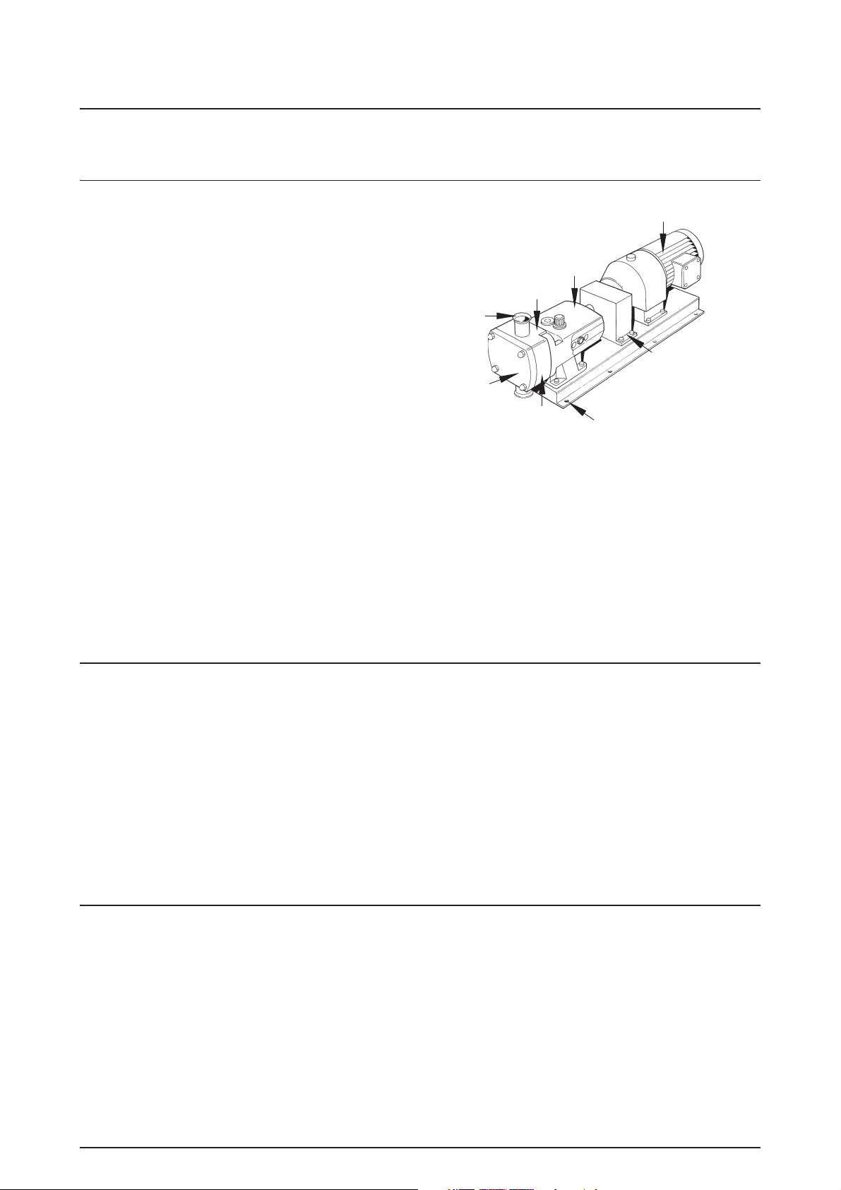
1.1 General description
The Series S pump supplied is a positive displacement rotary
lobe pump; it may be supplied with or without a drive unit (see
drawing). The drawing shown indicates various parts of the
pump unit.
1. General description
Drive unit
The Series S range has a universal gearbox design in models
S1 - 4. This enables the flexibility of mounting pumps with the
inlet and outlet ports in either a vertical or horizontal plane. The
port orientation, vertical or horizontal, may be changed by
Ports
Product
seal area
Gearbox
moving one of two available bolt-on feet on the gearbox. Port
orientation should be specified when ordering, but the
alternative foot design allows pumps that are already installed
being changed should the need arise.
Models S5 & 6 pumps can also have the inlet and outlet ports
in either horizontal or vertical plane. This is achieved by the use
Rotorcase
cover
Rotorcase
Baseplate fixing holes
Coupling guard
(encloses coupling)
of dedicated gearbox castings having either horizontal or
vertical shaft arrangements.
Pump duty conditions
The pump should only be used for the duty for which it has been specified. The operating pressure, speed and temperature limits
have been selected at the time of order and MUST NOT be exceeded. These details are stated on the original order
documentation and if not available may be obtained from your supplier quoting pump model and serial number.
Noise levels
Under certain operating conditions pumps and/or drives and/or the systems within which they are installed can produce sound
pressure levels in excess of 85dB[A]. When necessary, protection against noise should be taken.
8
2. Safety 2.1 Important information
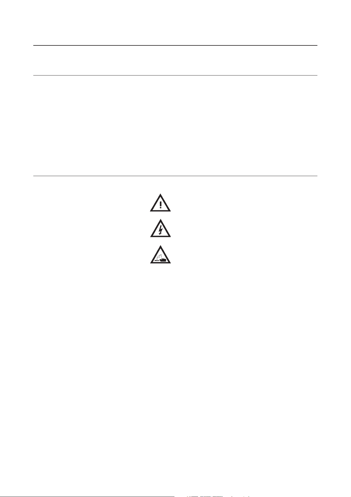
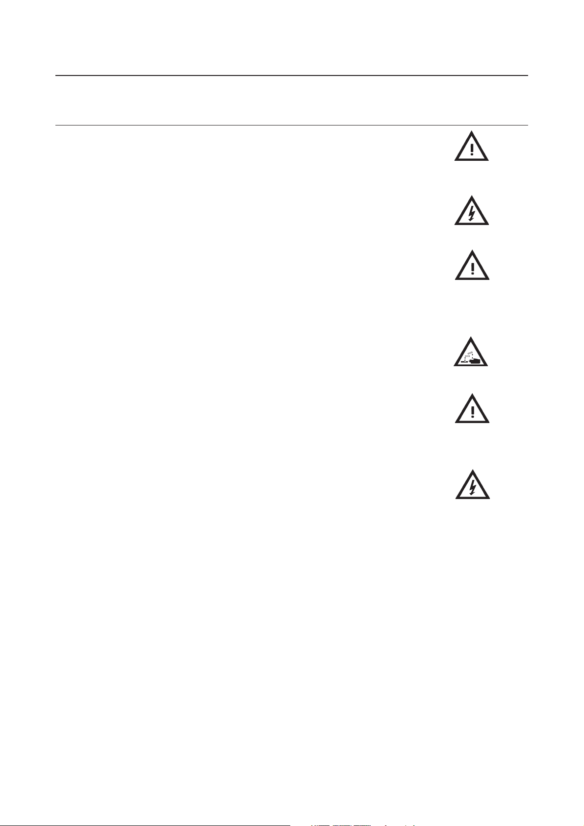
2.2 Warning signs
Unsafe practices and other important information are emphasized in this manual.
Warnings are emphasized by means of special signs.
Always read the manual before using the pump!
WARNING!
Indicates that special procedures must be followed to avoid severe personal injury.
CAUTION!
Indicates that special procedures must be followed to avoid damage to the pump.
NOTE!
Indicates important information to simplify or clarify practices.
General warning:
Dangerous electrical voltage:
Caustic agents:
9
2.3 Safety precautions 2. Safety
All warnings in the manual are summarised on this page.
Pay special attention to the instructions below so that severe personal injury or damage to the pump are avoided.
Installation
AlwaysAlways
-
Always observe the technical data (see chapter 5).
AlwaysAlways
NeverNever
-
Never start in the wrong direction of rotation with liquid in the pump.
NeverNever
NeverNever
-
Never put your hands or fingers inside the port connections or anywhere close to rotating
NeverNever
shafts.
The pump
supplied with the drive unit).
Operation
-
-
-
-
-
OnlyOnly
Only handle toxic and acidic liquids in accordance with their manufacturers instructions and
OnlyOnly
recommendations.
Maintenance
-
- The pump must
- The pump and the pipelines must
-
AlwaysAlways
Always disconnect the power supply when the pump is being serviced.
AlwaysAlways
must must
must be electrically connected by authorised personnel (see the motor instructions
must must
AlwaysAlways
Always observe the technical data (see chapter 5).
AlwaysAlways
NeverNever
Never touch the pump or the pipelines when pumping hot liquids or when sterilising.
NeverNever
NeverNever
Never stand on the pump or pipelines.
NeverNever
NeverNever
Never run the pump with both the suction side and the pressure side blocked.
NeverNever
NeverNever
Never put your hands or fingers inside the port connections or anywhere close to rotating
NeverNever
shafts.
AlwaysAlways
Always observe the technical data (see chapter 5).
AlwaysAlways
nevernever
never be serviced when hot.
nevernever
nevernever
never be pressurised when the pump is being serviced.
nevernever
NeverNever
Never put your hands or fingers inside the port connections or anywhere close to rotating
NeverNever
shafts.
10
3. Installation 3.1 Unpacking, Handling and Storage
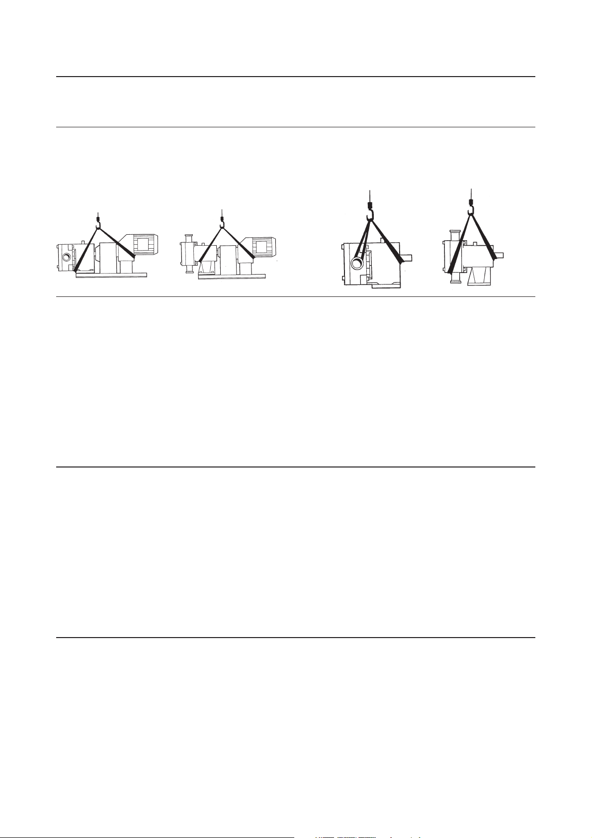
Step 1
Refer to the pump weights guide (chapter 5) before selecting and using any lifting gear. The drawings show how the pump should
be lifted.
Ensure that lifting equipment is correctly rated and used within these limits.
Pump with drive unit
Step 2
On receipt always:
- Check the delivery note against the goods received.
- If motorised, check that the drive instructions are available.
- Inspect the packing for signs of damage in transit.
- Carefully remove the packing away from the pump.
- Inspect the pump for any visible signs of damage.
- Clean away the packing from the pump port connections.
- Report any damage immediately to the carrier.
Step 3
After receipt and inspection, if the pump is not to be installed immediately, the pump should be repacked and placed in suitable
storage. The following points should be noted:
Bareshaft pump
- Plastic or gasket type port covers should be left in place.
- Pumps received wrapped with corrosion inhibiting treatment material should have wrapping replaced.
- A clean, dry storage location free from vibration should be selected. If a moist or dusty atmosphere is used for storage, further
protect the pump or unit with a suitable cover.
- Rotate the pump/pump unit by hand weekly, to prevent bearing damage.
- All associated ancillary equipment should be treated similarly.
11
3.2 System design and installation 3. Installation
Step 1
When designing the pumping system:
- Confirm the Net Positive Suction Head requirements of the
pump (NPSHr) are met by the system, as this is crucial for
ensuring the smooth operation of the pump and
preventing cavitation.
- Avoid suction lifts and manifold/common suction lines for
two pumps running in parallel, as this may cause vibration
or cavitation.
- Protect the pump against blockage from hard solid
objects e.g. nuts, bolts etc. Also protect the pump from
Plan view
accidental operation against a closed valve by using one of
the following methods: - relief valves, pressure switch, and
current limiting device.
Step 2
Before the pump is installed it is advisable to consider the following:
Always
- ensure that the mounting surface is flat to avoid distortion of the baseplate, as this will cause pump/motor shaft misalignment
and pump / motor unit damage.
Check
- pump shaft to motor shaft alignment is within manufacturers limits once the base plate has been secured.
Always allow at least 1 m for pump access / maintenance all around the pump.
- Fit suction and discharge pressure monitor points for diagnostic purposes.
- Fit valves if two pumps are to be used on manifold/common discharge lines.
- Make the necessary piping arrangements if flushing is required for the seal or if media is required for heating/cooling jackets.
- Do not subject the pump to rapid temperature changes. Pump seizure can result from thermal shock.
Discharge line
Suction line
Step 3
All pipework must be supported. The pump must not be allowed to support any of the pipework weight beyond the limits set in
the following table.
Remember:
Pipework supports must also support the weight of the product being pumped.
Always:
- Design short straight suction lines to reduce friction losses in the pipework thereby improving the NPSH available from the
system.
- Avoid bends, tees and any restrictions close to either suction or discharge side of pump. Use long radius bends wherever
possible.
- Provide isolating valves on each side of the pump to isolate the pump when necessary.
- Keep pipework horizontal where applicable to reduce air locks. Include eccentric reducers onsuction lines.
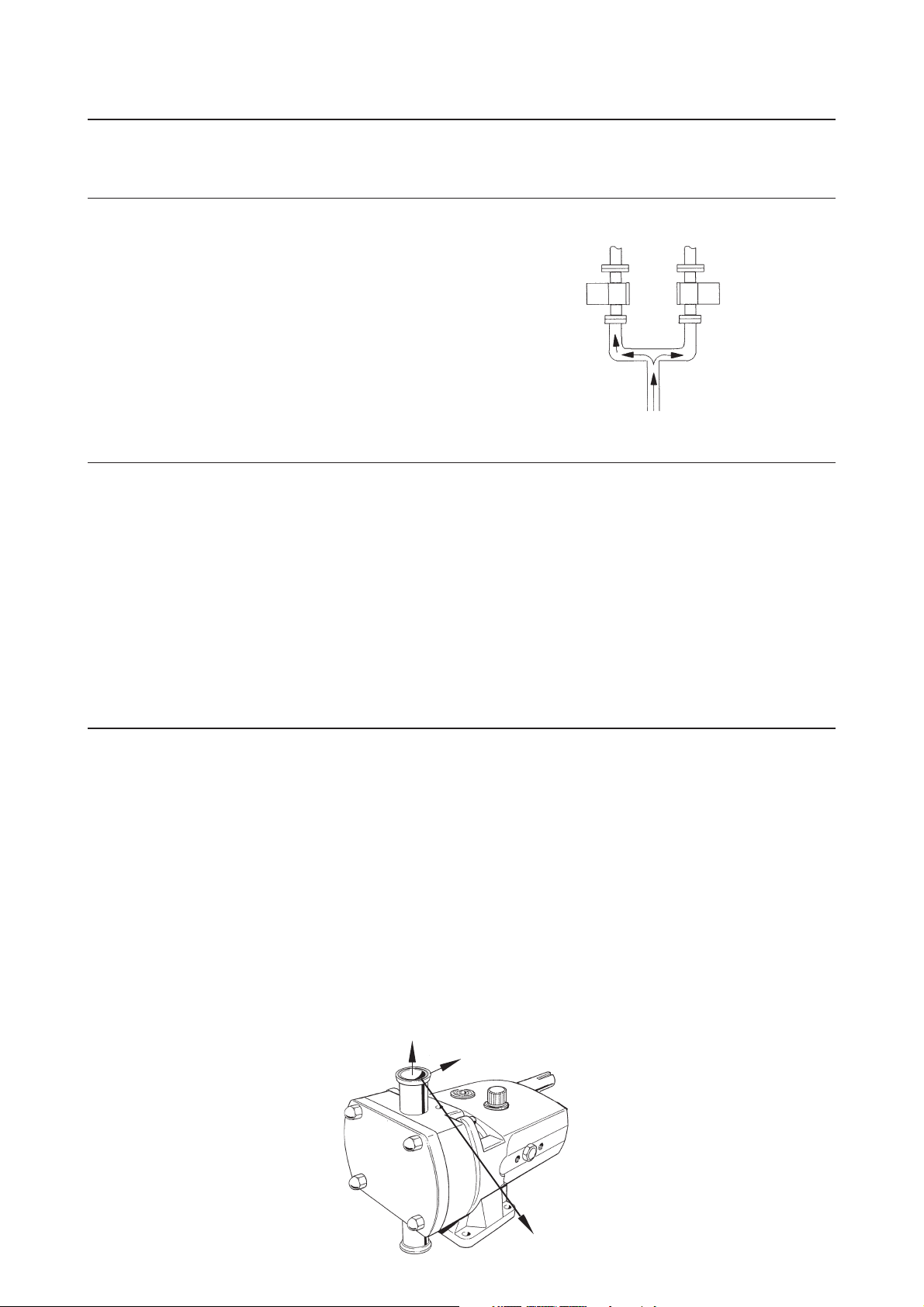
Plane ‘X’
Plane ‘Z’
12
Plane ‘Y’
3. Installation 3.2 System design and installation
Step 3 - continued
Table of Maximum Forces and Moments
Pump Forces Moments
Model FZ FY FX EF MZ MY MX EM
S1 Forces N 80 60 70 120
lbf 18 13 16 27
Moments Nm 75 90 115 165
lbft 55 66 85 122
S2 Forces N 125 100 110 195
lbf 28 22 25 44
Moments Nm 90 105 130 190
lbft 66 77 96 140
S3/4 Forces N 165 135 150 260
lbf 37 30 34 58
Moments Nm 100 115 140 205
lbft 74 85 103 151
S5/6 Forces N 300 250 250 460
lbf 67 56 56 103
Moments Nm 125 145 175 260
lbft 92 107 129 192
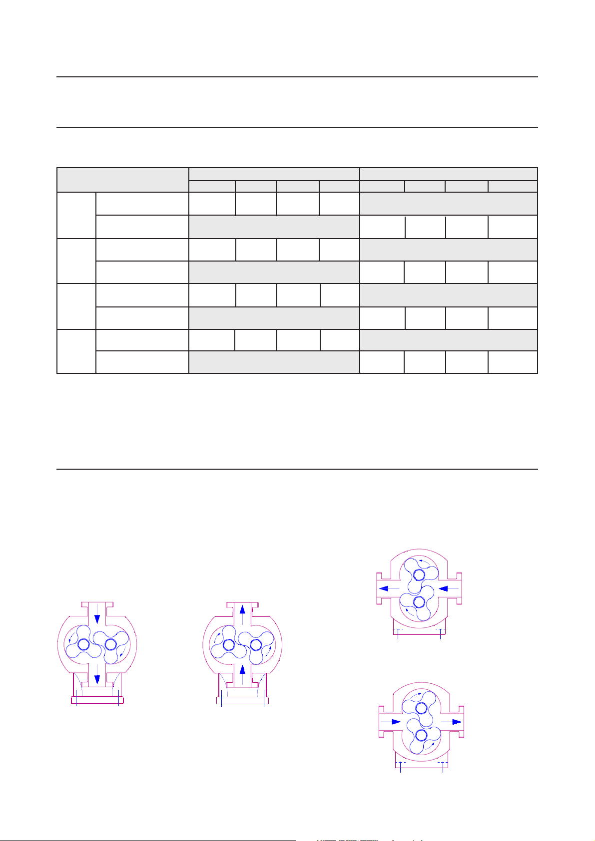
Step 4
The direction of flow is dictated by the direction of rotation of the drive shaft. Reversing the direction of rotation will reverse the
flow direction.
Suction Discharge
SuctionDischarge
Discharge
Suction
DischargeSuction
13

3.2 System design and installation 3. Installation
Step 5
The pump will not be supplied pre-filled with oil therefore this
table must be used to select recommended oil.
Oil changing: Oil level must be checked with the pump static.
First change: After 150 hours of operation, thereafter every
3000 hours of operation.
Oil filling: Fill with oil through the filler plug to the level indicated
in the sight glass.
NOTE!
On horizontally ported pumps the sight glass must be fitted to
the upper hole on the side of the gearcase.
Refer to technical data (chapter 5) for oil quantities required.
-20°C to +130°C +130
(-4°F to +266°F (+266°F to 392°F)
BP Energol GR - XP150 BP GRS15
Castrol Alpha SP150 Castrol Alpha SN150
Mobil Gear 629 Mobil Glycoyle 30
Shell Omala 150 Shell Tivela WA
Texaco Meropa 150 Texaco Synlube SAE90
Esso Spartan EP150 Esso IL1947
Pump Operating Temperature
o
C to 200°C
14

3. Installation 3.3 Flushed seal arrangements
and pre-start up checks
Step 1
A flushed seal arrangement is fitted in order to cool or clean the seal area.
It is important that:
- The flush is correctly connected (see below).
- A compatible flushing fluid is used and supplied at the correct pressure and flow rate.
- The flush is turned on at the same time/prior to starting the pump, and turned off at the same time/after stopping the
pump.
Step 2
Connecting the flush
The following equipment is strongly recommended when using a flushing system:
- Control valve and pressure gauge, to enable the correct flushing pressure to be obtained and monitored.
- Isolation valve and check valve, so that the flush can be turned off, and to stop any unwanted substances flowing in
the wrong direction.
- A method of visibly indicating flushing fluid flow.
Step 3
Flusing pipework
This suggested arrangement is for single mechanical seals. If
the pump is fitted with double mechanical seals or packed
glands the pressure gauges and control valves should be
fitted on the outlet side of the system.
Suggested visible indication of flow
Pipework & fittings not normally supplied by
pump manufacturer
Control valve
Check valve
Isolation valve
Flush inlet
Control
valve
Flush outlet to waste
Pressure gauge
Pressure gauge
Double mechanical
seal/packed gland
only
15
 Loading...