

SSP SAFIX Operating Instructions Manual

SSP Safety System Products GmbH & Co. KG
Max-Planck-Str. 21
D-78549 Spaichingen
www.safety-products.de
Translation of the original operating instructions
. All
rights reserved. Errors and omissions excepted.
Optionale Funktionen werden Ihnen ergänzend zu dieser
Betriebsanleitung entsprechend der Ausstattung Ihres
Gerätes in Form von Beiblättern zur Verfügung gestellt.
Inhaltsverzeichnis
Version 4.0
December 2017
EN Operating instructions
SAFIX
Safety sensor
1 About this document. . . . . . . . . . . . . . . . . . . . . . . . . . . . . . . . . . . . . . . .2
1.1 Function. . . . . . . . . . . . . . . . . . . . . . . . . . . . . . . . . . . . . . . . . . . . . . . . . . . . . . .2
1.2 Safety instructions for authorised qualifi ed personnel . . . . . . . . . . . . . . . . . . . . .2
1.3 Symbols . . . . . . . . . . . . . . . . . . . . . . . . . . . . . . . . . . . . . . . . . . . . . . . . . . . . . . .2
1.4 Appropriate use . . . . . . . . . . . . . . . . . . . . . . . . . . . . . . . . . . . . . . . . . . . . . . . . .2
1.5 General safety instructions . . . . . . . . . . . . . . . . . . . . . . . . . . . . . . . . . . . . . . . . .2
1.6 Warning about misuse . . . . . . . . . . . . . . . . . . . . . . . . . . . . . . . . . . . . . . . . . . . .2
1.7 Exclusion of liability . . . . . . . . . . . . . . . . . . . . . . . . . . . . . . . . . . . . . . . . . . . . . .2
2 Product description. . . . . . . . . . . . . . . . . . . . . . . . . . . . . . . . . . . . . . . . .2
2.1 Ordering code. . . . . . . . . . . . . . . . . . . . . . . . . . . . . . . . . . . . . . . . . . . . . . . . . . .2
2.2 Special versions . . . . . . . . . . . . . . . . . . . . . . . . . . . . . . . . . . . . . . . . . . . . . . . . .2
2.3 Destination and use . . . . . . . . . . . . . . . . . . . . . . . . . . . . . . . . . . . . . . . . . . . . . .2
2.4 Series connection . . . . . . . . . . . . . . . . . . . . . . . . . . . . . . . . . . . . . . . . . . . . . . . .2
2.5 Technical data . . . . . . . . . . . . . . . . . . . . . . . . . . . . . . . . . . . . . . . . . . . . . . . . . . 3
2.6 Safety classifi cation. . . . . . . . . . . . . . . . . . . . . . . . . . . . . . . . . . . . . . . . . . . . . . .3
2.7 Forseeable defeat according to ISO 14119 . . . . . . . . . . . . . . . . . . . . . . . . . . . . .3
3 Mounting. . . . . . . . . . . . . . . . . . . . . . . . . . . . . . . . . . . . . . . . . . . . . . . . .3
3.1 General mounting instructions . . . . . . . . . . . . . . . . . . . . . . . . . . . . . . . . . . . . . .3
3.2 Mounting accessories . . . . . . . . . . . . . . . . . . . . . . . . . . . . . . . . . . . . . . . . . . . . .4
3.3 Dimensions. . . . . . . . . . . . . . . . . . . . . . . . . . . . . . . . . . . . . . . . . . . . . . . . . . . . .4
3.4 Switching distance . . . . . . . . . . . . . . . . . . . . . . . . . . . . . . . . . . . . . . . . . . . . . . .5
3.5 Adjustment. . . . . . . . . . . . . . . . . . . . . . . . . . . . . . . . . . . . . . . . . . . . . . . . . . . . .5
4 Electrical connection. . . . . . . . . . . . . . . . . . . . . . . . . . . . . . . . . . . . . . . .5
4.1 General information for electrical connection. . . . . . . . . . . . . . . . . . . . . . . . . . . .5
5 Operating principles and coding. . . . . . . . . . . . . . . . . . . . . . . . . . . . . . .5
5.1 Mode of operation of the safety outputs . . . . . . . . . . . . . . . . . . . . . . . . . . . . . . .5
5.2 Coding. . . . . . . . . . . . . . . . . . . . . . . . . . . . . . . . . . . . . . . . . . . . . . . . . . . . . . . .6
6 Diagnostic functions . . . . . . . . . . . . . . . . . . . . . . . . . . . . . . . . . . . . . . . .6
6.1 Operating principle of the diagnostic LED‘s . . . . . . . . . . . . . . . . . . . . . . . . . . . . .6
7 Set-up an maintenance . . . . . . . . . . . . . . . . . . . . . . . . . . . . . . . . . . . . . .7
7.1 Funktionsprüfung . . . . . . . . . . . . . . . . . . . . . . . . . . . . . . . . . . . . . . . . . . . . . . . .7
7.2 Wartung. . . . . . . . . . . . . . . . . . . . . . . . . . . . . . . . . . . . . . . . . . . . . . . . . . . . . . . 7
8 Disassembly and disposal . . . . . . . . . . . . . . . . . . . . . . . . . . . . . . . . . . . .7
8.1 Disassembly . . . . . . . . . . . . . . . . . . . . . . . . . . . . . . . . . . . . . . . . . . . . . . . . . . . .7
8.2 Disposal . . . . . . . . . . . . . . . . . . . . . . . . . . . . . . . . . . . . . . . . . . . . . . . . . . . . . . .7
9 Appendix . . . . . . . . . . . . . . . . . . . . . . . . . . . . . . . . . . . . . . . . . . . . . . . . .8
9.1 Wiring examples. . . . . . . . . . . . . . . . . . . . . . . . . . . . . . . . . . . . . . . . . . . . . . . . . 8
9.2 Anschlussbelegung und Zubehör Steckverbinder . . . . . . . . . . . . . . . . . . . . . . . . .9
10 Declaration of conformity. . . . . . . . . . . . . . . . . . . . . . . . . . . . . . . . . . .10
10.1 EU-Declaration of conformity . . . . . . . . . . . . . . . . . . . . . . . . . . . . . . . . . . . . . .10
1. About this document
1.1 Function
This operating instructions manual provides all the information you need for the mounting,
set-up and commissioning to ensure the safe operation and disassembly of the safety switchgear. The operating instructions must be available in a legible condition and a complete
version in the vicinity of the device.
1.2 Safety instructions for authorised qualified personnel
All operations described in this operating instructions manual must be carried out by trained
specialist personnel, authorised by the plant operator only. Please make sure that you have
read and understood these operating instructions and that you know all applicable legislations regarding occupational safety and accident prevention prior to installation and putting
the component into operation. The machine builder must carefully select the harmonised
standards to be complied with as well as other technical specifi cations for the selection,
mounting and integration of the components.
1.3 Symbols
Caution
Failure to comply with this warning notice could lead to physical injury and/or
damage to the machine.
Information
Hilfreiche Zusatzinformationen
1.4 Appropriate use
The products described in these operating instructions are developed to execute safety-related
functions as part of an entire plant or machine. It is the responsibility of the manufacturer
of a machine or plant to ensure the correct functionality of the entire machinery or plant.
The safety switchgear must be exclusively used in accordance with the versions listed below
or for the applications authorised by the manufacturer. Detailed information regarding the
range of applications can be found in the chapter „2. Product description“.
1.5 General safety instructions
The user must observe the safety instructions in this operating instructions manual, labelled
with the caution or warning symbol above, the country-specifi c installation standards as
well as all prevailing safety regulations and accident prevention rules.
Further technical information can be found in the SSP catalogues or in the
online catalogue on the Internet: www.safety-products.de.
The information contained in this operating instructions manual is provided without liability
and is subject to technical modifi cations.
There are no residual risks, provided that the safety instructions as well as the instructions
regarding mounting, commissioning, operation and maintenance are observed.
1.6 Warning about misuse
In case of inadequate or improper use or manipulations of the safety switchgear,
personal hazards or damages to machinery or plant components cannot be
excluded. The relevant requirements of the standard
ISO 14119 must be observed.
1.7 Exclusion of liability
We shall accept no liability for damages and malfunctions resulting from defective mounting
or failure to comply with this operating instructions manual. The manufacturer shall accept
no liability for damages resulting from the use of unauthorised spare parts or accessories.
For safety reasons, invasive work on the device as well as arbitrary repairs, conversions
and modifi cations to the device are strictly forbidden; the manufacturer shall accept no
liability for damages resulting from such invasive work, arbitrary repairs, conversions and/
or modifi cations to the device.
2. Product description
2.1 Ordering code
This operating instructions manual applies to the following types:
Type code SAFIX
Coding variations
➀
➀ ➁
S Standard coding
I Individual coding
W Individual coding, re-teachable
T Transmitter (actuator)
➁ Option
1 Diagnostic output
3 Standard actuator
4 Flacher actuator
2.2 Special versions
For special versions, which are not listed in the order code below 2.1, these specifi cations
apply accordingly, provided that they correspond to the standard version.
2.3 Destination and use
This non-contact, electronic safety switch is designed for application in safety circuits and
is used for monitoring the position of movable safety guards. In this application, the safety
switch monitors the position of hinged, sliding or removable safety guards by means of
the coded electronic actuator.
The safety function consists of safely switching off the safety outputs when the safety guard
is opened and maintaining the safe switched off condition of the safety outputs for as long
as the safety guard is open.
2.4 Series connection
Series connection can be set up. The response and risk times are not altered by wiring in
series. The number of components is only limited by the external cable protection according
to the technical data and the line loss.
Protection is not required when pilot wires are laid. The cables however must be separated
from the supply and energy cables. The max. fuse rate for a sensor chain depends on the
section of the connecting cable of the sensor.
The entire concept of the control system, in which the safety component is
integrated, must be validated to the relevant standards.
2.5 Technical data
Standards: IEC 60947-5-3, IEC 61508, ISO 13849-1
Enclosure: Thermoplastic hotmelt
Operating principle: RFID
Frequency band: 125 kHz
Transmission power: max. -6 dBm
Actuator: SAFIX T3
Series connections: Unlimited number of components,
lease observe external cable protection
Connection: Connector plug M8, 8-pole, A-coded
Switching distances according to IEC 60947-5-3
Typical switching distance: 12 mm;
- lateral actuation: 9 mm
assured switching distance Sao: 10 mm;
- lateral actuation: 6 mm
assured swtiching distance Sar: 18 mm;
- lateral actuation: 15 mm
Hysteresis: < 2,0 mm
Repeat accuracy R: < 0,5 mm
Ambient conditions
Ambient temperature Tu: −25 °C … +65 °C
Storage and transprot temperature: −25 °C … +85 °C
Protection class: IP65 / IP67 to IEC 60529
Resistance to vibration: 10 … 55 Hz, Amplitude 1 mm
Resistance to shock: 30 g / 11 ms
Switching frequency f: 1 Hz
Drop-out time:
- Actuator ≤ 100 ms
Duration of risk: ≤ 200 ms
Time to readiness: ≤ 2 s
Electrical data
Rated operating voltage Ue: 24 VDC −15% / +10%
(PELV to IEC 60204-1)
Rated operating current Ie: 0,6 A
Minimum operating current Im: 0,5 mA
Required rated short-circuit current: 100 A
Rated insulation voltage Ui: 32 V
Rated impulse withstand voltage Uimp: 800 V
No-load current Io: 35 mA
Overvoltage category: III
Degree of pollution: 3
Safety inputs X1/X2
Rated operating voltage Ue1: 24 VDC −15% / +10%
(PELV unit)
Power consumption per input: 5 mA
Safety outputs Y1/Y2 p-type, short-circuit proof
Operating current Ie1: max. 0,25 A
Utilisation category: DC-12: Ue/Ie: 24 VDC / 0,25 A;
DC-13: Ue/Ie: 24 VDC / 0,25 A
Voltage drop: Ue < 1 V
Diagnostic output p-type, short-circuit proof
Operating current Ie2: max. 0,05 A
Utilisation category: DC-12: Ue/Ie: 24 VDC / 0,05 A;
DC-13: Ue/Ie: 24 VDC / 0,05 A
Voltage drop: Ue < 2 V
Operating current: 150 mA
Wiring capacitance: max. 50 nF
Device fuse rating: ≤ 2 A bei Einsatz gemäß UL 508
2.6 Safety classification
Standards: EN ISO 13849-1, IEC 61508, IEC 62061
PL: e
Category: 4
PFH value: 6,8 x 10
-10
/ h
PFD: 1,2 x 10
SIL: suitable for SIL 3 applications
Service life: 20 years
2.7 Forseeable defeat according to ISO 14119
SAFIX S low coding level
SAFIX I high coding level
SAFIX W high coding level
3. Mounting
3.1 General mounting instructions
During fi tting, the requirements of ISO 14119 must be observed.
The mounting holes provide for a variable mounting by means of M4 screws (max. tightening
torque 0.8 Nm). The component can be mounted in any position. The labelled surfaces of
the safety switch and the actuator have to be opposite. The safety switch must only be used
within the assured switching distances ≤
and ≥
sao
.
sar
Safety switch and actuator must be permanently fitted to the safety guards
and protected against displacement by suitable measures (tamperproof screws,
gluing, drilling of the screw heads).
The mounting holes provide for a variable mounting by means of M4 screws (max. tightening
torque 0.8 Nm). The component can be mounted in any position. The labelled surfaces of
the safety switch and the actuator have to be opposite. The safety switch must only be used
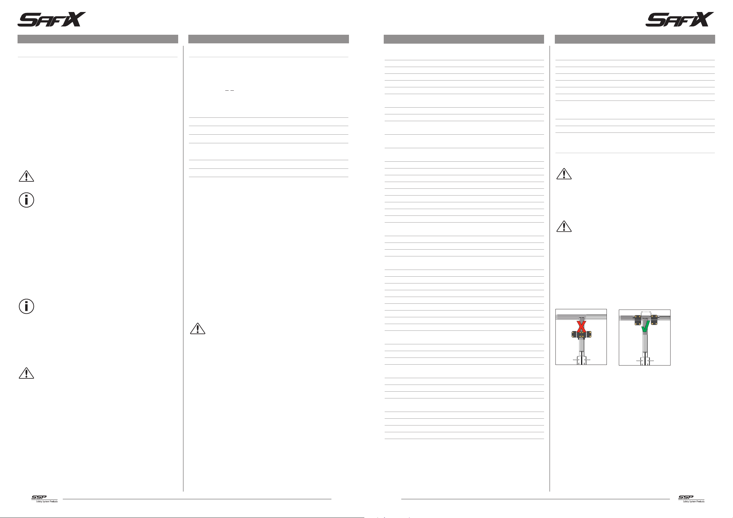
within the assured switching distanTo avoid any interference inherent to this kind of system
and any reduction of the switching distances, please observe the following guidelines:
• The presence of metal chips in the vicinity of the sensor is liable to modify the switching
distance.
• Keep away from metal chips.
• Minimum distance between two sensors: 100 mmes ≤
100 mm
and ≥
sao
.
sar
Wrong Right
-4
2 3
 Loading...