

SSP CAM/TZ YG-LED318 User Manual
USER MANUAL
YG-LED318
CAM/TZCAM/TZ
3.6--DMX512 SETTINGS....................................................................10.
PART 4 USING A DMX512 CONTROLLER....................................15.
4.1--BASIC ADDRESSING.................................................................15.
4.21--CHANNEL ASSIGNMENT .......................................................15.
4.31--BASIC INSTRUCTIONS FOR DMX512 OPERATION .................23.
PART 3 DISPLAY PANEL OPERATION.........................................6.
3.1--BASIC..........................................................................................6.
3.2--MENU..........................................................................................7.
3.4--ACTIVATING AUTO PROGRAMS.................................................10.
3.7--PERSONALITY...........................................................................11.
3.8--ID ADDRESS..............................................................................11.
3.10--SPECIAL SETTINGS.................................................................12.
3.13--A CTIVATE THE PASSWORD .................................................... 14.
3.9--EDITING CUSTOM PROGRAMS ................................................ 12.
3.12--RGB CALBRATION .................................................................. 14.
PART 1 PRODUCT (GENERAL)....................................................1.
1.1--TECHNICAL SPECIFICATIONS.....................................................1.
1.2--SAFETY WARNING......................................................................2.
PART 2 INSTALLATION...............................................................3.
2.1--MOUNTING...................................................................................3.
2.3--SETTING UP WITH A DMX512 CONTROLLER.................................3.
2.3-1--DMX512 ADDRESSING WITHOUT ID ADDRESSING......................................4.
2.3-2--DMX512 ADDRESSING WITH ID ADDRESS..................................................4.
2.2--POWER CONNECTION..................................................................3.
3.3--EDIT STATIC COLOUR.................................................................9.
PART 5 APPENDIX......................................................................25.
5.1--MAINTENANCE......................................................................... 25.
3.5--RUN MODE................................................................................ 10.
3.11--WHITES SETTING ....................................................................13.
ABLE OF CONTENTS
T
25
4.22--CHANNEL ASSIGNMENT .......................................................20.
4.32--BASIC INSTRUCTIONS FOR DMX512 OPERATION .................24.
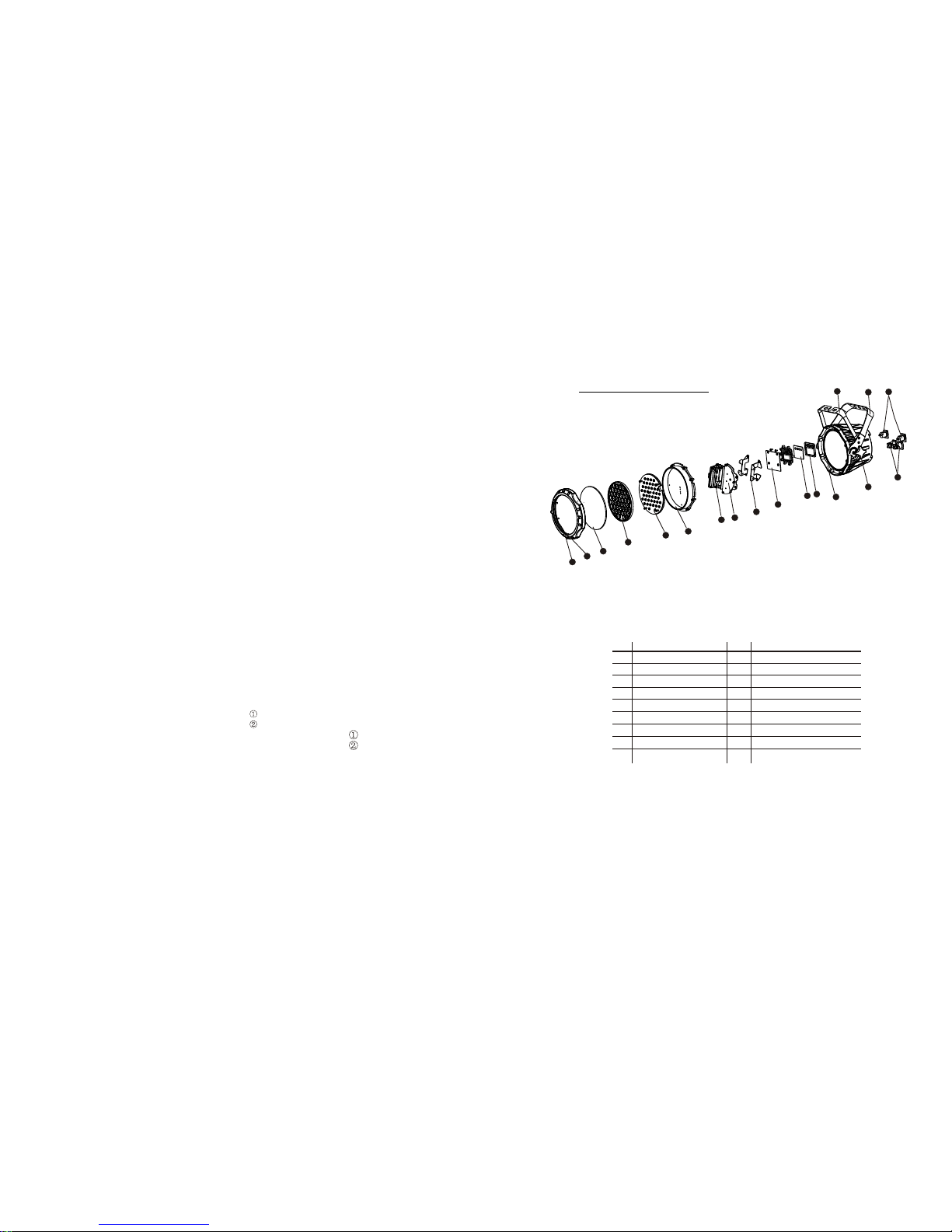
5.1 MAINTENANCE
1
2
3
4
5
6
7
8
9
10
Front cover
Rubber seal
Clear glass
Lens completed set
LED PCB
Heat sink
Power supply
Power connection board
Display PCB
Driver PCB
Casing
Adjusting stainless steel knob
No
ITEM
Display clear plate
Button seal
11
12
13
14
15
16
17
18
No
ITEM
1
2
3
4
5
6
7
8
9
10
11
12
13
14
15
16
17
18
±ÈÀý 25.400
Main support
Secondary support
Power cable socket
DMX cable socket
5 APPENDIX
1 PRODUCT (GENERAL)
1.1 TECHNICAL SPECIFICATIONS
LED MODULE
24
1
Model
Voltage
Operation
Temperature
Weight
Dimensions 2
mm
Power
W
IP
AC100~240V
50/60Hz
-20~45
4.8
245x205x245
CW:1Wx24
WW:1Wx18
R:1Wx12
G:1Wx12
B:1Wx12
W:1Wx6
CW:1Wx24
WW:1Wx18
IP67
R:1Wx12
G:1Wx12
B:1Wx12
W:1Wx6
IP67
70
245mm
205mm
245mm
30mm
13mm
30mm
Type
4.32 BASIC INSTRUCTIONS FOR DMX512 OPERATION (STD.2)
MASTER DIMMER
CH1 controls the intensity of the currently projected color
When the slider is at the highest position (255) the intensity of the output is
the maximum
COOL WHITE & WARM WHITE SELECTION
CH2 and CH3 control the intensity ratio of each of the WARM WHITE &
COOL WHITE LEDs.
When the slider is at the highest position (255) the intensity of the color is
the maximum.
CH2 and CH3 can be combined together to create whites with different
color temperature.
STROBE
CH 5 controls the strobe of CH1 to CH4
CH5 has priority over CH2, CH3 & Ch4.
WHITE MACRO
Ch4 allow user to select 5 whites with different color temperature.
The 5 whites are took from the CAL1 on Display panel.
ID ADDRESS SELECTION
Ch6 is used to select the target ID address.
Each independent DMX address may have upto 66 independent ID
addresses.
An ID address of 0 will activate all ID address locations.
APPLY:(LED318WW/LED318WWT)
70
50
50
1.2 SAFETY WARNING
IMPORTANT
ALWAYS READ THE USER MANUAL BEFORE OPERATION.
PLEASE CONFIRM THAT THE POWER SUPPLY STATED ON THE
PRODUCT IS THE SAME AS THE MAINS POWER SUPPLY IN YOUR
AREA.
This product must be installed by a qualified professional.
Always operate the equipment as described in the user manual.
A minimum distance of 0.5m must be maintained between the
equipment and combustible surface.
The product must always be placed in a well ventilated area.
Always make sure that the equipment is installed securely.
DO NOT stand close to the equipment and stare directly into the LED
light source.
Always disconnect the power supply before attempting and
maintenance.
Always make sure that the supporting structure is solid and can
support the combined weight of the products.
The earth wire must always be connected to the ground.
Do not touch the power cables if your hands are wet.
ATTENTION
This product left the place of manufacture in perfect condition. In
order to maintain this condition and for safe operation, the user must
always follow the instructions and safety warnings described in this
user manual.
Avoid shaking or strong impacts to any part of the equipment.
Make sure that all parts of the equipment are kept clean and free of
dust.
Always make sure that the power connections are connected correct
and secure.
If there is any malfunction of the equipment, contact your distributor
immediately.
When transferring the product, it is advisable to use the original
packaging in which the product left the factory.
Shields, lenses or ultraviolet screens shall be changed if they have
become damaged to such an extent that their effectiveness is
impaired.
The lamp (LED) shall be changed if it has become damaged or
thermally deformed.
2 23
4.31 BASIC INSTRUCTIONS FOR DMX512 OPERATION (TOUR)
MASTER DIMMER
CH1 controls the intensity of the currently projected color
When the slider is at the highest position (255) the intensity of the output is the
maximum
RED, GREEN & BLUE & WHITE COLOR SELECTION
CH2, CH3 & CH4 & CH5 control the intensity ratio of each of the RED, GREEN,
BLUE & WHITE LEDs.
When the slider is at the highest position (255) the intensity of the color is the
maximum.
CH2, CH3, CH4 & CH5 can be combined together to create over 16 million colors.
COLOR MACROS
CH6 selects the required COLOR MACRO
CH6 has priority over CH2, CH3, CH4 & CH5
CH1 is used to control the intensity of the COLOR MACRO
STROBE
CH 7 controls the strobe of CH1 to Ch6
ID ADDRESS SELECTION
Ch11 is used to select the target ID address.
Each independent DMX address may have upto 66 independent ID addresses.
An ID address of 0 will activate all ID address locations.
AUTO
CH8 selects the preset AUTO programs AT.01-AT.10 or the custom AUTO
programs CUS.01-CUS.10
When activating the custom AUTO programs CUS.01 to CUS.10 then it is possible
to control the STEP TIME and FADE TIME using CH2 and CH3 respectively.
CH8 has priority over CH2, CH3, CH4, CH5, CH6 & CH7.
DIMMER SPEED
CH10 is for selecting the dimmer mode and dimmer speed. When DIMMER is set
to Off , then RGBW and MASTER DIMMER are linear. The Dim 1/2/3/4 are
different speed of the non linear dimmer .
APPLY:(LED318XW/LED318XWT)
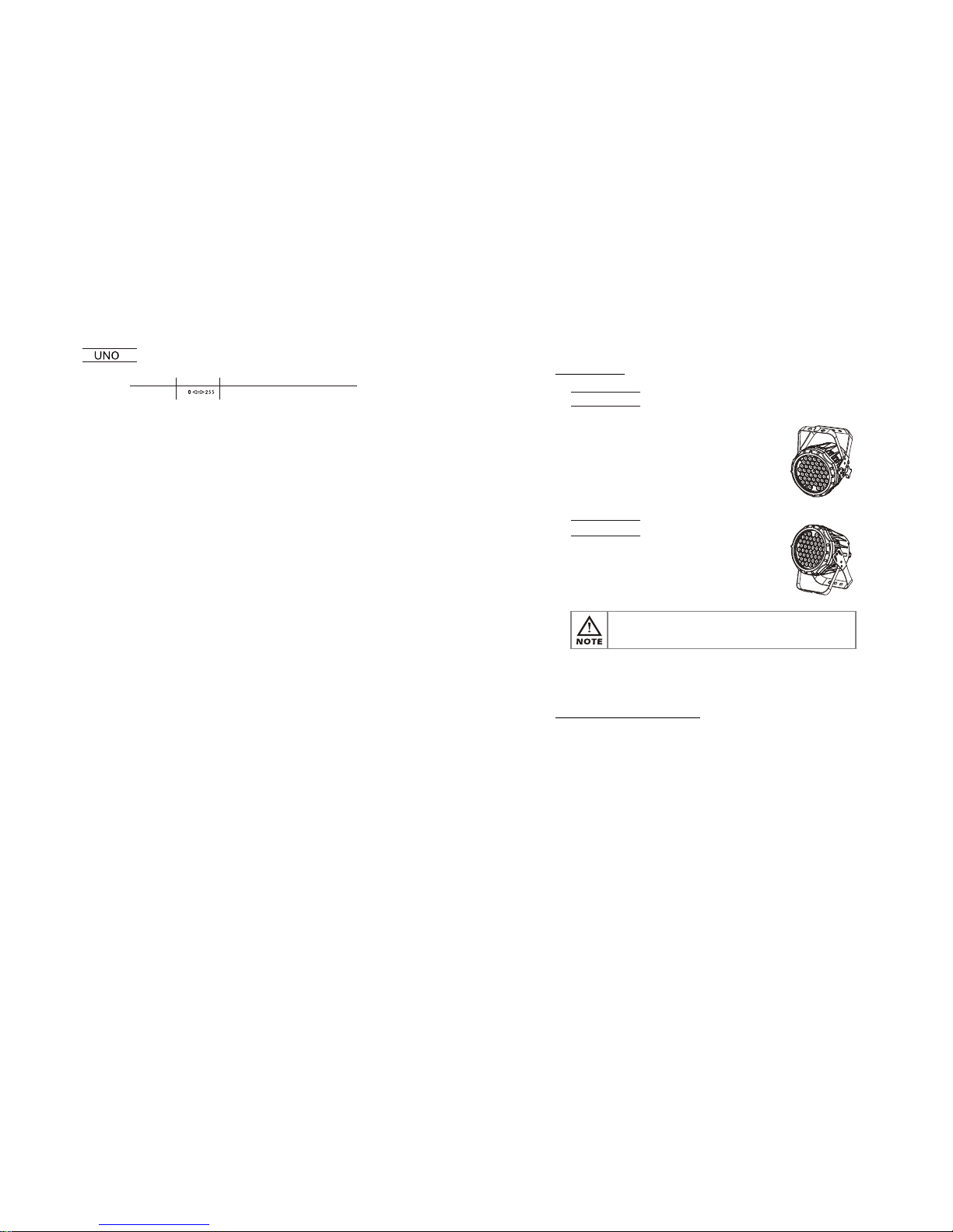
2.1 MOUNTING
HANGING
UPRIGHT
The fixture can be mounted in an
upright or sitting position using the
supporting brackets.
The fixture can be mounted in a
hanging position using the supporting
bracket. The bracket should be
secured to the mounting truss or
structure using a standard mounting
clamp. Please note that when hanging
the unit a safety cable should also be
used.
@ 220V: 24 units may be connected in series
@120V: 12 units may be connected in series
The LED MODULE can be mounted at any angle and in any
position. It is possible to further adjust the angle of the LED
MODULE using the two adjustment knobs located on the side of
the fixture.
2.2 POWER CONNECTIONS
Note:
If the signal cable is over 60m between the DMX512 controller and fixture
or beween two fixtures, then a DMX signal amplifier is needed as well.
2 INSTALLATION
22 3
STATIC SETTING FROM DISPLAY MENU
1
CHANNEL FUNCTIONVALUE
 Loading...