

Page 1
Page 2
3.6” Bluetooth-Enabled In-Dash
DVD/MP3/CD Receiver with USB, SD
Memory Card Ports and Front Panel AV Input
Page 3
1. HANDLING COMPACT DISCS
MOISTURE CONDENSATION
On a rainy day or in a very damp area, moisture may condense on the lenses inside the unit.
Should this occur, the unit will not operate properly. In such a case, remove the disc and wait for
about an hour until the moisture has evaporated.
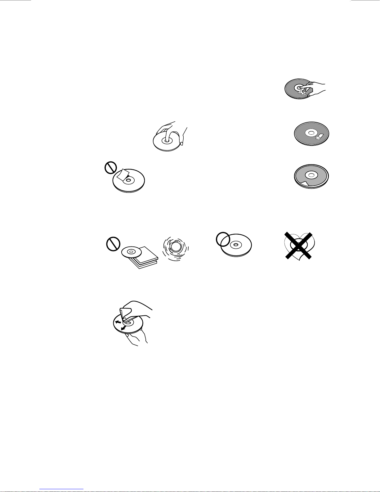
NOTES ON CDs
1.
A dirty or defective disc may cause sound
dropouts while playing. To enjoy optimum
sound, handle the disc as follows.
Handle the disc by its edge. To keep the disc
clean, do not touch the surface (P.1).
P. 1
Do not stick paper or tape on the disc (P.2).
2.
Paste or sticky residue.
****
*******
*******
*******
P. 5
*******
Do not use CDs with old labels that are
beginning to peel off.
Stickers that are beginning
to peel away leave a
sticky residue (P.6).
P. 6
**************
*******
*******
*******
Do not use CDs with labels or stickers
attached.
P. 2
Do not expose the discs to direct sunlight or
3.
heat sources such as hot air-ducts, or leave
them in a car parked in direct sunlight where
there can be a considerable rise in
temperature inside the car (P.3).
P. 3
Before playing, clean the discs with an
4.
optional cleaning cloth. Wipe each disc from
the centre out (P.4).
P. 4
Do not use solvents such as benzine,
5.
thinner,commercially available cleaners, or
antistatic spray intended for analog discs.
NOTES ON DISCS
If you use the discs explained below, the sticky
residue can cause the CD to stop spinning and
may cause malfunction or ruin your discs.
Do not use CDs that have a sticky residue on the
surface (for example, from peeled-off stickers or
from ink, or glue leaking from under the
stickers).
Labels are attached (P.7).
P. 7
*******
*******
*******
*******
*******
Do Not Use Special Shape CDs
Be sure to use round shape CDs only. Do
not use any special shape CDs. Use of
special shape CDs may cause the unit to
malfunction.(P.8).
P. 8
CD-Rs and CD-RWs which have not
undergone finalization processing cannot
be played. (For more information on
finalization processing, refer to the manual
for your CD-R/CD-RW writing software or
CD-R/CD-RW recorder.) Additionally,
depending on the recording status, it may
prove impossible to play certain CDs
recorded on CD-R or CD-RW.
E - 1
E - 1
Page 4
2. INSTALLATION
Before finally installing the unit, connect the wiring temporarily and make sure it is all
connected up properly and the unit and system work properly.
Use only the parts included with the unit to ensure proper installation. The use of
unauthorized parts can cause malfunctions.
Consult with your nearest dealer if installation requires the drilling of holes or other
modifications of the vehicle.
Install the unit where it does not get in the driver's way and cannot injure the passenger if
there is a sudden stop, like an emergency stop.
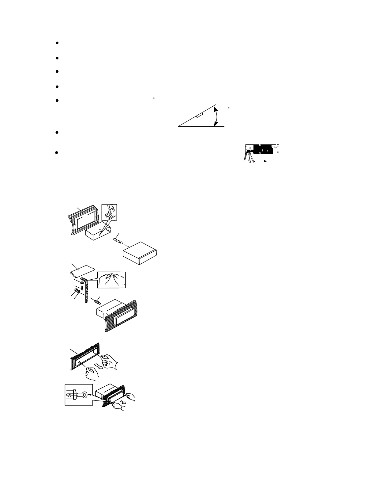
If installation angle exceeds 30 from horizontal, the unit might not give its optimum
performance.
Avoid installing the unit where it would be subject to high temperature, such as from direct
sunlight, or from hot air, from heater, or where it would be subject to dust dirt or excessive
vibration.
Be sure to remove the front panel before installing the unit.
DIN FRONT/REAR-MOUNT
This unit can be property installed either from “Front” (conventional DIN Front-mount) or
“Rear”(DIN Rear-mount installation, utilizing threaded screw holes at the sides of the unit
chassis). For details, refer to the following illustrated installation methods A and B.
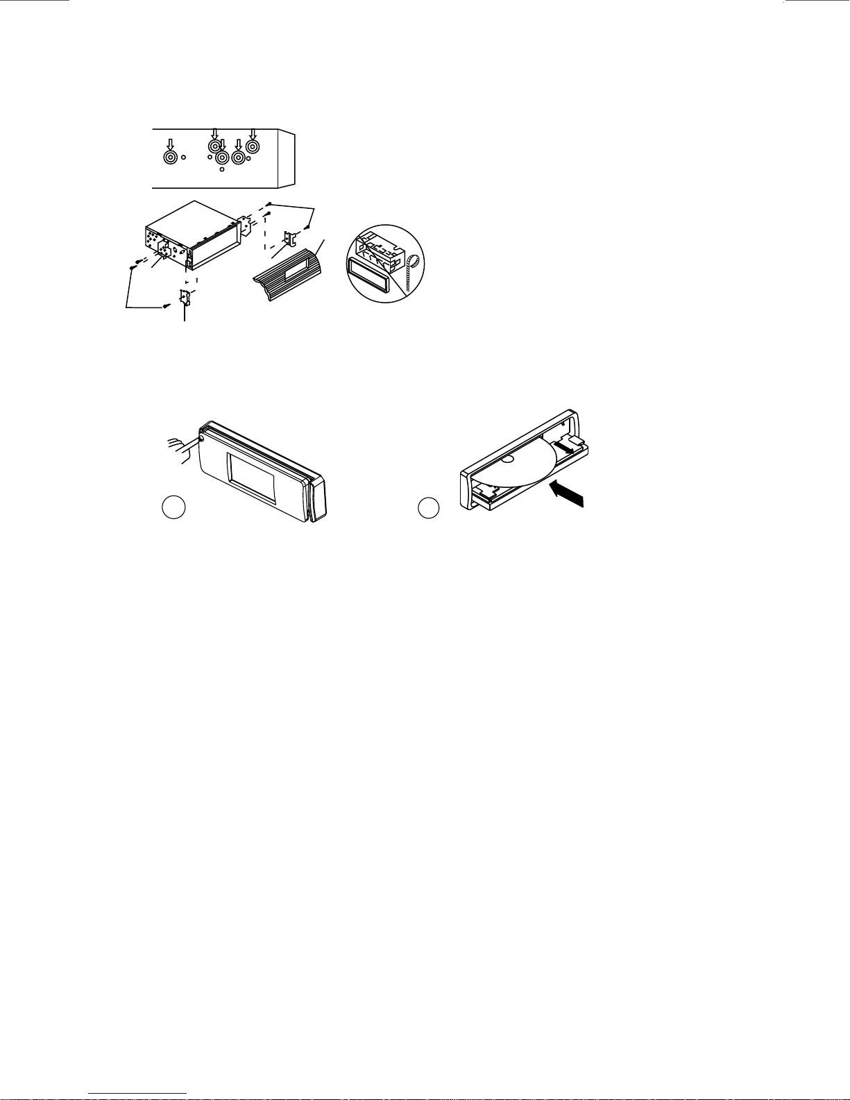
DIN FRONT-MOUNT (Method A)
Installation the unit
1
182
53
1
7
4
2
3
6
2
3
5
Removing the unit
a
b
c
Trim Plate Installation:
Push the trim plate against the chassis until it is fitted.
You must do this before you install the front panel, otherwise it can't be attached.
1. Dashboard
2. Holder
After inserting the half sleeve into the dashboard,
select the appropriate tab according to the
thickness of the dashboard material and bend
them inwards to secure the holder in place.
3. Screw
1. Dashboard
2. Nut (5mm)
3. Spring washer
4. Screw (4x12mm)
5. Screw
6. Support Strap
Be sure to use the support strap to secure the
back of the unit in place. The strap can be bent by
hand to the desired angle.
7. Plain washer
a. Frame
b. Insert fingers into the groove in the front of frame
and pull out to remove the frame. (When reattaching the frame, point the side with a groove
down wards and attach it.)
c. Insert the levers supplied with the unit into the
grooves at both sides of the unit as shown in
figure until they click. Pulling the levers makes it
possible to remove the unit from the dashboard.
30
RCA LINE OUT JACK(OPTION)
E - 2
Page 5
DIN REAR-MOUNT (METHOD B)
Installation using the screw holes on the sides of the unit.
Fastening the unit to the factory radio mounting bracket.
1. Select a position where the screw holes of
the bracket and the screw holes of the main
unit become aligned (are fitted) and tighten
the screws at 2 places on each side.
2
4
2. Screw(must not use more than 6mm length)
3. Factory radio mounting bracket.
4. Dashboard or Console
5
3
5. Hook (Remove this part)
Note: the mounting box, outer trim ring,
and half-sleeve are not used for method B
2
5
installation.
PANEL OPEN/CLOSE OPERATION
T
E
S
E
R
1
2
IN
D
C
1. Press Open button
2. The CD slot will be accessible.
3. After CD is loaded or unloaded return the panel to its original position.
E - 3
Page 6
3. DETACHABLE CONTROL PANEL (D.C.P.)
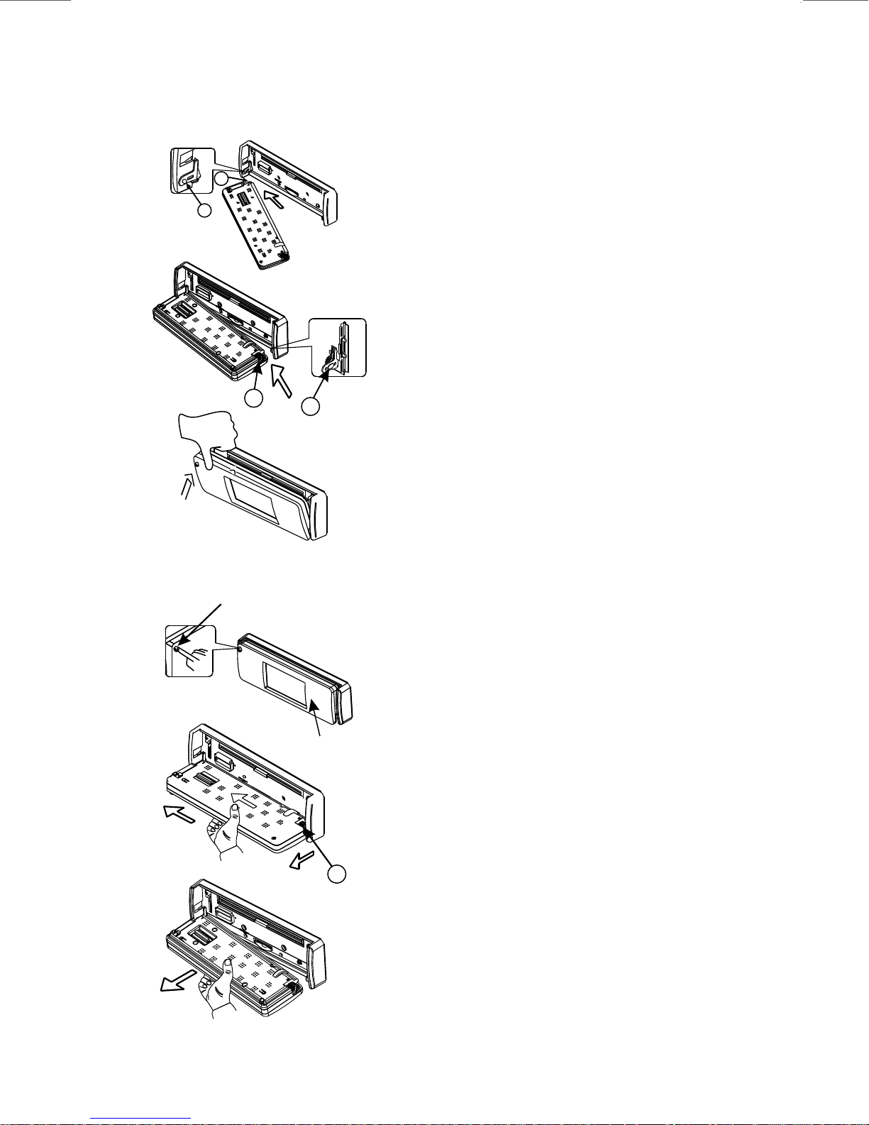
Attaching the Detachable Control panel (D.C.P.)
B
A
D
PUSH
C
Removing The Detachable Control Panel (D.C.P.).
OPEN
BUTTON
1. Attach the panel at the Left side first,
with point B on the main unit touching
point A on the D.C.P
(As shown on the diagram).
2. And then also attach the panel at the
right side , with point C on the main unit
touching point D on the D.C.P as well
(As shown on the diagram)
3. Then press the left side of D.C.P onto the
main unit until a “click” sound is heard.
D.C.P.
1. Turn the power off.
2. Press the panel open button,
the D.C.P will be fold down.
3. Push hard the D.C.P in the left direction
until the point D at the right side of D.C.P
is came off the main unit
(As shown on the diagram).
D
3. Remove the D.C.P.
E - 4
Page 7

CAUTION
DO NOT insert the D.C.P from the right side. Doing so may damage it.
The D.C.P can easily be damaged by shocks. After removing it, place it in a protective case and be careful not
to drop it or subject it to strong shocks.
When the open button is pressed and the D.C.P is unlocked, the car's vibrations may cause it to fall. To prevent
damage to the D.C.P, always store it in a protective case after detaching it.
The rear connector that connects the main unit and the D.C.P is an extremely important part. Be careful not to
damage it by pressing on it with fingernails, pens, screwdrivers, etc.
Note:
If the D.C.P is dirty, wipe off the dirt with soft,
dry cloth only. And use a cotton swab soaked
in isopropyl alcohol to clean the socket on the
back of the D.C.P.
Socket
E - 5
Page 8
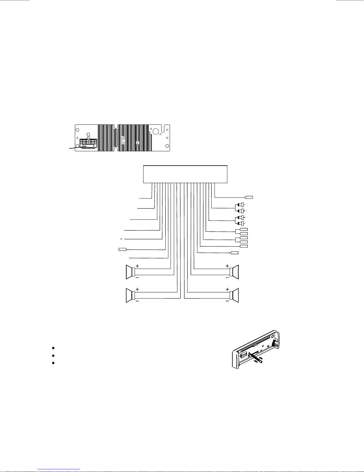
4. ELECTRICAL CONNECTION
a. Make sure your car battery is a 12 volt (6 filler caps) negative ground system (if not, a
converter will be necessary).
b. Before starting wiring connections, disconnect the power supply by removing the fuse from
the fuse box.
c. Connect the power wire to one of the extra terminals of the fuse box.
d. Connect the black ground wire to a metal part of the car. It is important to make good
e. Make other wiring connections as shown.
f. If your car does not have ISO connector, you can purchase it from car accessory shops.
Notes: INCORRECT WIRING OR OPERATION WILL VOID THE WARRANTY OF THIS UNIT.
contact.
FUSE
(CAR UNIT BACK SIDE)
(+)
PINK
ORANGE
RED
YELLOW
(FUSED)
BLACK
GREY
AUTO ANT.
BLUE
WHITE
WHITE / BLACK
GREEN/BLACK
PARKING BRAKE(-)
REVERSE(+12V)
OVERRIDE WIRE
SWITCHED
CONSTANT
GOUND ( )
SUB-WOOFER
FRONT
LEFT
SPEAKER
REAR
LEFT
SPEAKER
12V+
12V+
BLUE
GREEN
Fuse Replacement:
To replace the fuse, pull out the blown fuse
from the socket. Insert a new one with same rating
MAIN UNIT
ANTENNA
CONNECTOR
RCA OUTPUT
BLACK
(REAR)
RCA OUTPUT
GREY
AUDIO IN
VIDEO OUT (1)/(2)
VIDEO IN
REVERSE VIDEO IN
GREY
GREY / BLACK
VIOLET
VIOLET / BLACK
(FRONT)
RED
WHITE
RED
WHITE
RED
WHITE
YELLOW
YELLOW
YELLOW
YELLOW
FRONT
RIGHT
SPEAKER
REAR
RIGHT
SPEAKER
RESET BUTTON
The RESET button is located on the main unit (as shown on the diagram). Press it vertically
with a ballpoint pen or metal object to activate it. The reset button should be activated for the
following reasons:
Initial installation of the unit when all wiring is completed.
All the function buttons do not operate.
Error symbol on the display.
Note: If you press the RESET button, and the unit still cannot function normally, please use a
cotton swab soaked in isopropyl alcohol to clean the socket on the back of the control panel.
E - 6
Page 9
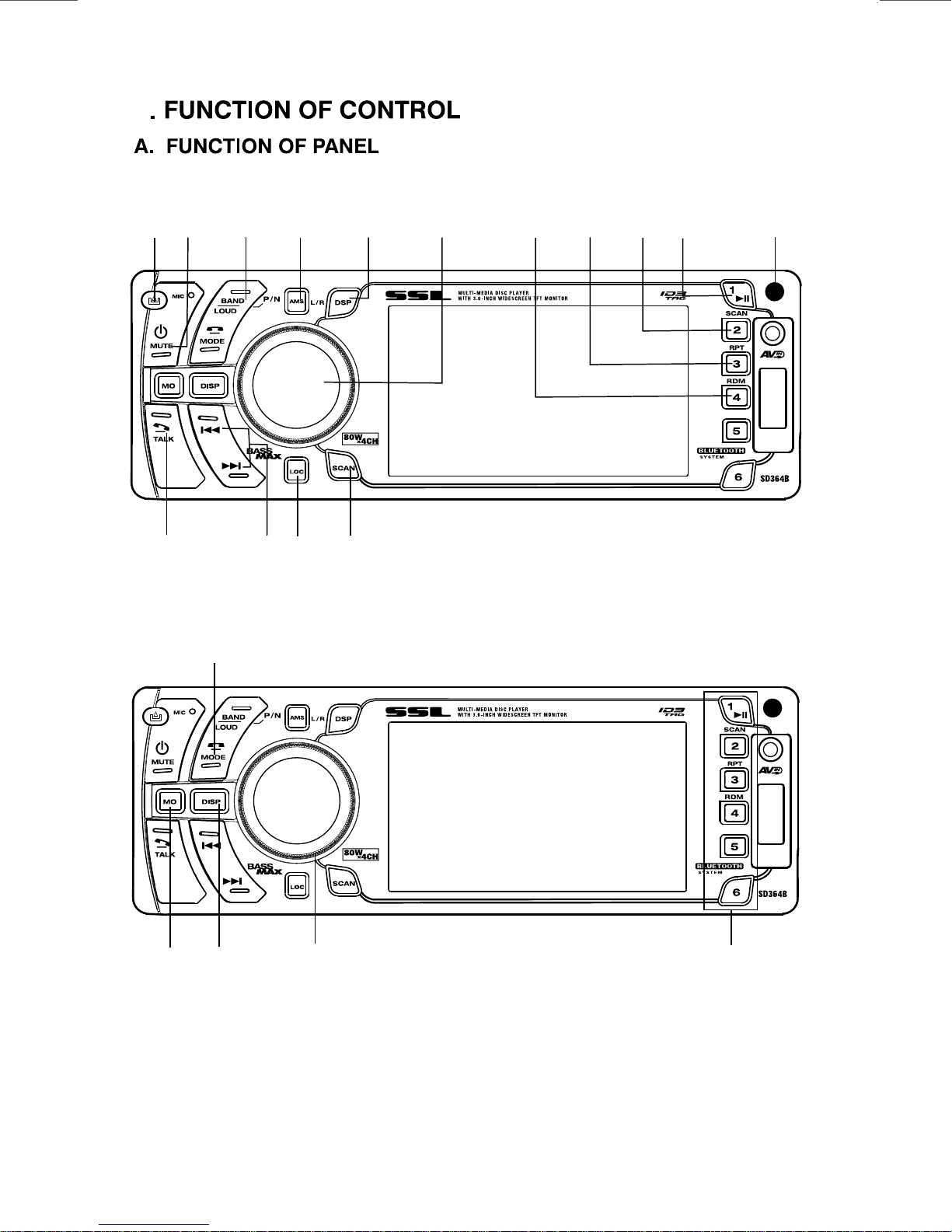
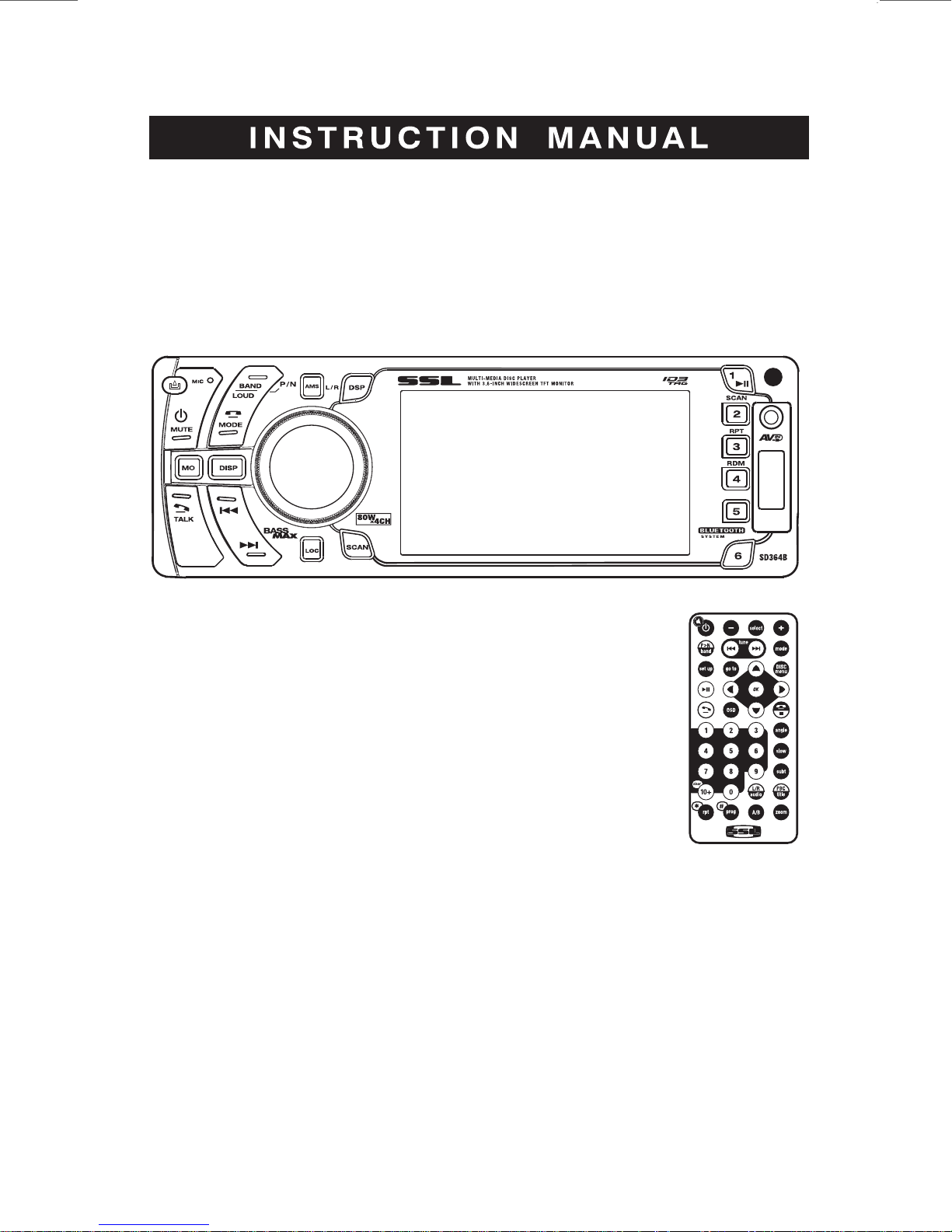
5
PANEL
OPEN
BUTTON
TALK
BUTTON
POWER/
MUTE
BUTTON
HANG UP/
MODE
BUTTON
APL/
NTSC/
BAND/
LOUDNESS
BUTTON
TUNING /
SEEK
UP/DOWN
NEXT/BACK
BUTTON
AMS
BUTTON
LOCAL/
DX
BUTTON
DSP/
LEFT/
RIGHT
BUTTON
SCAN
BUTTON
FUNCTION
SELECT
BUTTON
CD
RANDOM
BUTTON
CD
REPEAT
BUTTON
CD
SCAN
BUTTON
CD
PAUSE
BUTTON
INFRARED
REMOTE
SENSOR
FM
STEREO /
MONO
BUTTON
DISPLAY
BUTTON
ENCODER
VOLUME
KNOB
E - 7
PRESET MEMORY BUTTONS
(M1-M6)
Page 10

B. FUNCTION OF REMOTE
E - 8
Page 11

6. BASIC OPERATION
PANEL RELEASE BUTTON
Press this button to remove the control panel.
POWER BUTTON
Press power button to turn on/off the unit.
DISPLAY BUTTON(DISP)
Press this button briefly,the LCD will display the clock for about 5 seconds, then return to
previous display mode.
Clock Adjustment
Under clock display mode,press DISP button until the LCD flashes,USE VOLUME UP/DOWN to
Adjust hour & minute,press sel button to change the hour & minute.
MUTE BUTTON ( MUTE)
Press MUTE button to mute the sound quickly. the display is flashing Press it again to restore the
previous sound level. When mute is on, the Mute indicator on the LCD will light up.
LOUDNESS BUTTON (LOUD)
Long press this LOUD button control to increase bass output.
MODE BUTTON
Press this button to select radio, DISC/USB/SD/MMC/A/V-IN FRONT/A/V-IN Rear.
FRONT PANEL A/V IN JACK
The unit is allowed to connect the with external Audio /
Video system such like Digital Camera or Game Console.
You can connect the external A/V system thru the A/V in
jack on front panel. After connect with external A/V
system, pressing mode to “A/V IN FRONT” to enjoy this
external A/V system on this unit.
(MODE)
1
Left Audio
2
Right Audio
3
Ground
4
Video
3.5mm A/V Cable ( not included )
NOTE: The unit is only support the 3.5mm A/V Jack Pin Assignment shown as the diagram delete
extra "."
SELECT BUTTON (SEL)
press SEL button for less than 1 second to open the Audio menu.
press SEL repeatedly to navigate through the following functions:
VOLUME (VOL) -> BASS (BAS) -> TREBLE (TRE) -> BALANCE (BAL) -> FADER (FAD)->SUBWOOFER(SUB-W)
Press Volume Up/Down to adjust desired level within 5 seconds.
NOTE: BASS AND TREBLE WILL BE SKIPPED IF DSP MODE IS ACTIVATED
ENCODER VOLUME KNOB
Turn this knob to adiust desired volumelevel.
PRESET EQUALIZER BUTTON (DSP)
Press this PEQ button then use V-UP / V-DN to toggle the following EQ settings.
POP -> ROCK -> CLASSIC -> DSP OFF
At DSP off mode preset equalizer will be controlled by Bass / Treble setting.
E - 9
Page 12

8. RADIO OPERATION
FM MONO / STEREO BUTTON (MONO)
Use this control to select stereo or mono reception for FM radio stations. You can sometimes improve
reception of distant stations by selecting mono mode.
LOCAL / DX BUTTON (LOC)
This control can be used to change between Local and Distant (-DX) tuning mode. Local mode
improves reception in some areas where the signal is too strong.
STATION PRESET BUTTONS (M1-M6)
You can store & recall six preset radio stations by pressing M1-M6 buttons
TO STORE A STATION: 1) select a band (if needed)
2) select a station by tuning up / down button
3) hold a preset button which you want store the station for at least 2
seconds. The preset number will appear on the display accompanied by
a beeps sound.
TO RECALL A STATION: 1) select a band (if needed)
2) press a preset button briefly to recall the stored station.
SCAN BUTTON (SCAN)
Press this button, the radio will tune up to search stations, the available stations will blinking and stay
on the display for a few seconds.
AUTO MEMORY STORE / PRESET SCAN BUTTON (AMS)
PRESET SCAN: press AMS button for less than 1 second to scan all preset stations in the memories
of the current band and stay on each memory stations for about 5 seconds. The
memory location indicator on the LCD will flash during the process. To stop preset
scan, press AMS button again.
AUTO MEMORY STORE: press AMS button for more than 1 second to enter auto store mode. The
radio will automatically store 6 stations to the 6 preset memories of the current band. To stop auto
store, press AMS button again.
BAND BUTTON (BAND)
Press this button to change between band FM1, FM2, FM3 or MW(AM)1, MW(AM)2 bands .
TUNING UP / DOWN BUTTON ( )
Press this button to search for radio stations. Depends on whether SEEK1 or SEEK 2 mode is
selected, different operations can be performed, refer to “SEEK MODE” paragraph for detail.
DUAL FREQUENCY SWITH
Unit is defaulted in U.S.A. Frequency, if EURO frequency is required, a sharp pen is needed to switch
the button on the left side of the chassis to EURO frequency.
EU
US
E - 10
Page 13

9. Blue Tooth Hand Free Panel / Remote Control Function Key Matrix
2
HANG UP/MODE
BUTTON
(Short Press)
1
TALK
BUTTON
TALK BUTTON
NUMBERIC KEY FOR TEL
DIALING BUTTONS
1
3
2
HANG UP/STOP
(short press)
Panel Function Button Blue Tooth Hand Free Function
1
2
TALK
HANG UP/MODE
(short press)
Remote control Button
1
TALK
Please refer to the page E-16 Item 1 & 2.
1. Reject Incoming call
2. End a call
Blue Tooth Hand Free Function
Make an Outgoing call press “TALK” Button once to ready
input the Tel number what you want to phone and the tel
number you dialed will be showed on the Display. Once you
press the “TALK” again to dial the number and the “DIALING”
will, be showed on display. During the talking mode, the Display
will showed “TALKING”.
2
3
HANG UP/STOP
(short press)
Numberic Key
1. Reject incoming call
2. End a call
1. For tel dialing (During make an out going call)
2. For “CLEAR/+10” key if you have wrong input the Tel number,
you can use this key to correct the wrong number on the
display before you send the TEL number out.
E - 11
Page 14

BLUETOOTH MODE OPERATION
INSTRUCTION FOR HANDSFREE FUNCTION
1. PAIR IT WITH YOUR PHONE (PAIRING)
Before you use your Car HANDSFREE System,you need to pair it with your mobile phone.
1. The Bluetooth set system on the head unit will automatically go into pairing mode when the
Ignition is being turned on and the Bluetooth symbol indicator on the display will
Flash every 1 second.
2. Set your Bluetooth phone to ‘discover’ the “CAR_A2DP_HF”.
3. Your phone will find the “CAR_A2DP_HF”.
Your phone then asks if you want to pair with it. Accept by pressing ‘Yes’ or ‘OK’ on the phone
and confirm with the passkey or PIN=0000 (4 zeros). Your phone will confirm when pairing is
complete. The Bluetooth symbol will stop flashing and stay lit.
In case of unsuccessful pairing, repeat steps 1 to 3 .
2. OPERATION
Call Accept: Single click TALK button during an incoming call to accept the call.
Call Reject: Click “CANCEL”(MODE) or (STOP) on the remote during an incoming call will
reject the call.
Call End: Single click TALK button when communication or dialing an outgoing call to hang
up.
Call Disconnect: Click TALK button about 1.5 seconds when it is not in communication
mode. “And Disconnect” and “No LINK” will showed on the display.
Call Re-connect,Click TALK button again at the Disconnect Status. The connection will be
reconnected and “LINKING” & “LINK OK” will showed on the display.
Call Waiting (Depend on provider feature): Double click TALK button at communicating time,
enter into call waiting, double click it again, enter into communication mode.
Call Transfer (Private mode): Click TALK button about 1.5 seconds at communicating time,
transfer the call to phone, click talk button once again, transfer the call to Bluetooth.
Last Number Redial: Double click TALK button when not in call automatically redial the last
number.
Auto Answer (Depend on mobile phone feature): Pls refer to your own mobile phone manual
for handsfree auto answer setting.
Volume Adjust: User can use the volume up/down to adjust the volume level.
3. WHAT DISPLAY CAN SHOW DURING THE INCOMING/OUTGOING CALL MODE
INCOMING CALL
When there is an incoming call, the display will display the “Incoming caller telephone
number” If the incoming call has no caller number, the LCD will display “00000000” user can
short press the “TALK” button answer / accept the call and the “Talking”display will be
showed when the call is answered.
To end the conversation, press the “CANCEL(MODE” or “(STOP)” at the Remote control and
the “Hang up” will showed on display. The unit and the display on the LCD will switch back
to the previous mode automatically.
OUTGOING CALL
User can use his / her Mobile Phone or remote control to dial and make an outgoing call .
Once the user start dialing, the display should show “DIALING”.
The audio output of the present mode will ONLY be muted after pressing the “TALK” button
as a confirmation to dial the outgoing call.
During talking mode, the LCD Display will display “TALKING”.
To end the conversation, press the “CANCEL (MODE)” button or “(STOP)” at the Remote
control and the “Hang up” will showed on display. The unit and the display on the LCD will
switch back to the previous mode automatically. The mute of the previous mode will be
released at the same time.
E - 12
Page 15

4. BLUETOOTH NOTICE
Before you start to use our Bluetooth HEAD UNIT , Please pair the unit with your mobile
phone completely. Please refer to the section of “PAIRING” To ensure the best reception for
Pairing & Re-connection, please make sure the phone Battery is fully charged when making
the pairing or Re-connection.
Every time you turn the ignition key from off to on, the unit will automatically re-connect with
the mobile phone.
By pressing the TALK button the unit will start the Auto-Reconnection . In some conditions,
the user will need to reconnect manually. For example like the following.
If the mobile phone is out of range. (2 meters away from the head unit) the unit will be
disconnected from the mobile phone.
If user wants to re-connect, it will have to be done manually.
The Bluetooth symbol (...) and the connected symbol (< / >) on the mobile phone will be
different from one to another. Please refer to the corresponding specification.
The LED turns on when an audio connection exists (e.g. talking) or when it is ringing.
When the main unit turns on, if there is a call incoming, it will auto switch to talk state.
When you hang up the phone, the main unit will revert to previous state (radio, CD or other
mode).
When the main unit turns off (with ACC ON), if there is a call incoming, the main unit will
auto turn on and enter into talk mode. When hang up the phone, the main unit will turn off
automatically.
Some Mobile Phone Brands like Sony Ericsson may have "Power Saving Mode" selection
when Blue Tooth mode is switched on. PLEASE DO NOT Switch ON “Power saving Mode”
when operating with this Head Unit, . As some abnormal communication behavior will
happen Power Saving Mode is switched on.
To ensure the best conversation quality / performance, please always keep talking within 1
meter of the Head Unit.
Some Mobile Phones can support “IN BAND RING TONE”, such as Motorola, Nokia. In
such case, the Incoming Ringing Tone will be same as the original Ring-tone of the Mobile
Phone. But some Mobile Phones like Sony Ericsson do not support this feature. The Ringtone will be using the standard Ring-tone of the Head unit.
Using voice dialing, please make sure the phone and the ‘head unit within 3 meters of each
other. Also please make sure your mobile phone support voice dialing function. And please
consult with your mobile phone supplier if you want to know the operation further about
voice dialing.
If user wants to Dis-connect the Head unit with the Mobile Phone, please click talk button
long once or switch "OFF" Blue Tooth connectivity on the Mobile Phone.
LISTENING TO MUSIC USING CAR-A2DP-HF ON THE BT AUDIO MODE
CAR-A2DP-HF is capable of streaming music over Bluetooth from a mobile phone
supporting A2DP. Press the mode button to select Bluetooth BT audio mode, once you have
paired your Car Handsfree with your mobile phone, use your phone to play, pause, stop,
skip forward and backward. When you receive a call, the music will be automatically paused
and you will be able to answer or reject a call through the headset. Once you end a call, the
music will continue. On some phones you may have to press ‘play’ to start the music again.
The LCD display of the head unit should show “A2DP” when playing music with CAR-A2DPHF.
And you can also make an outgoing call (This function is compatible with some phones
which can make outgoing calls during the A2DP mode.)
E - 13
Page 16

Specifications for Blue tooth
BLUE TOOTH
Power Consumption
Output Power
Frequency Band
Range
Standard
Specifications subject to change without notice.
200mA
0 dBm (Class II)
2.4GHz ~ 2.4835GHz ISM Band
3 meters (free space)
Bluetooth specification
Max.
2.0
Remark:
Our Bluetooth Handsfree System adapts to the Bluetooth spec V2.0 and higher. It is compatible
with profiles such as Handsfree profile and Head Set profile. However the functionality may be
limited due to some phones dedicated interfacing specifications, even with phones of which the
actual Bluetooth specifications and used profiles apply to our Bluetooth Handsfree System
specifications.
Please check the compatibility list or try it out in practice your phone at the local dealer in case
it is not mentioned in the list.
Note:
Compatibility and connectivity with all Bluetooth mobile phones is not guaranteed.
Warning:
Many jurisdictions have laws regarding the use of a phone in a vehicle environment. Obey all
local laws. Always keep your hands free to operate the vehicle while driving. Your first
consideration while driving should be road safety.
E - 14
Page 17

10. CD/MULTI-MEDIA FILE
LOADING THE CD
Press the Panel Open Button to fold down the front panel, insert the disc through CD slot, the
disc will be automatically loaded and playback will also start.
CD EJECT BUTTON
Press this button to eject the CD. Since this button is located behind the front panel, fold down
the panel before accessing this button.
T
SE
E
R
PLAY/PAUSE BUTTON ( )
Press this button briefly to pause disc play, press again to resume play.
INTRO SCAN BUTTON (CD SCAN)
Press this button to select Intro Scan function, the first 10 seconds of each track will be played
sequentially until this button is pressed again, then normal play will resume at the current track.
NOTE:This will only operate with the SCAN function play on CD.
REPEAT BUTTON(RPT)
Pressing this button will activate Repeat Function in the following order :
Repeat On Repeat Off
The RPT indicator will turn on.
RANDOM PLAY BUTTON(RDM)
When random play mode is selected, the tracks will be played in random order, press this key one
more time to cancel random play mode.
NEXT/BACK BUTTONS( & )
When NEXT is pressed, the unit will go to the next track and start the playback.
When BACK is pressed, the unit will go back to the previous track and start the playback.
Long press the & buttons under the play mode, the unit will start to forward or rewind. you
can play discs at various speeds. with each consecutive long press the & buttons , the
playback speed increases. there are 5 speed levels for discs in FWD/REV: X2, X4, X8, X16,X20.
there are 4 speed levels for disc types other than disc: X2, X4, X8,X16.
Press PLAY to resume the playback at normal speed.
E - 15
Page 18

MULTI-MEDIA FILE OR FOLDER SEARCHING
Selecting a Track to Play
1. Use the UP/DOWN/LEFT/RIGHT direction buttons to move to different file/folder
Numbers.
2. Press OK on a file number, and that file will begin to play, or by direct numeric input,
3. Enter a file number with the numeric buttons (0-9) and +10 button to play the input Files
Number.
REPEAT A-B BUTTON (A-B)
1. Press REPEAT A-B at your chosen starting point.
2. Press REPEAT A-B again at your chosen end point.
The section A and B can be set only within the same track.
The section will now repeat continuously.
3. To exit the sequence, press REPEAT A-B.
The screen will display the following message:
REPEAT A- REPEAT A- B REPEAT A-B CANCEL
NOTE:This operate is with CD function only.
STOP BUTTON( )
Stop the current disc playback.
button is pressed, normal playback will continue.
Press STOP two times consecutively to enter the clear stop mode. Under the clear stop mode, if
PLAY is pressed, the disc will resume the playback from the beginning of the disc.
Briefly press the STOP button to stop the unit playback, when the PLAY
NUMERIC BUTTONS
When playback CD/MUSIC use for track number or File number direct access and
Use when function need numeric Selection or Input, like in the Goto function, etc.
UP/DOWN/LEFT/RIGHT BUTTON ( / / / )
Use to move cursor up/down/left/right.
OK BUTTON
Use this button to confirm the selection.
GO TO BUTTON (GO TO)
Using GO TO feature to select track number or specific time.
A. Press GO TO button,the screen will display the following message:
TRK 001/021
B. Press Arrow Left/Right buttons to highlight the track number or the time option.
C. Use numeric buttons to enter the track you want to play or the elapsed time you want to
go to in that track.
D. Press OK button to start playback.For example, entering 00:01:56 will start playback one
minutes and fifty-six seconds into the title.
A
00:01: 56
E - 16
Page 19

PROGRAM BUTTON (PROG)
Press PROG button the screen will display the following message.
PROG
1 0002
2 0004
3 ---4 ---- 8 ----
A. For example:Press numeric button 2 ,PROGRAM 0002 appears it means track 2 will be
player first then press numeric button 4 and PROGRAM 0004 appears,press the different
numeric button to select the corresponding track and then you can program tracks to your
need if you want to complete program setting press PLAY button to play tracks in
programmed order.
B.Press the ( / / / )buttons to highlight select program mode or track number and
press PLAY button to confirm it.
C.If you exit program mode and program off appears press STOP button then press PLAY
button.
5 ---- 9 ---6 ----
7 ----
10 ---11 ---12 ----
PLAY
CLEAR
ID3 INFORMATION DISPLAY
If any MUSIC file any ID3-TAG information, user can view these ID3-TAG information such
as Track title, Artist title, Album title, etc, These ID3-TAG information will be displayed on the lower
left hand corner of the TFT monitor.
contains
13 ---14 ----
15 ---16 ----
E - 17
Page 20

11. PLAY MULTI-MEDIA FILES OPERATION
Place a disc into the player, and the player will auto search the directories saved files. After
searching, it will auto go to the first directory saved files (to the disc containing both Music and
photo files; To the disc containing single type of files, it will automatically go to the first directory) and
play the first song in the directory (“01:” is highlighted).The screen displays as the picture below:
Current directory name
Current file name.
File Switch Region: Displays the file type of the playing
and the switching.
The playing file is a Photo File.
The playing file is a Music File.
Use the Arrow ( / / / )buttons to enter the Directory Region and highlight the desired directory, then the
first track under it starts playback; Also you can use the Arrow( / / / ) buttons to enter the File Region and
select the file you want to play.
NOTE:
NOTE:
Press the Left and Right arrow buttons, you can activate Directory Region, File Region and
File Switch Region separately.
The highlight in Directory Region and File Region is shown as the picture above; While it
appears a transparent rectangle in File Switch Region.
You can press the Numeric buttons to select the file you want to play. For example, if you
desire the 15 track in current list, press the “10+” button once, then press “5”, the 15
th th
starts playback.
When a picture , press the Arrow buttons to change the display
is playing or paused
angle:
E - 18
Page 21

12. MMC/SD CARD & USB DEVICE OPERATIONS
START THE USB DEVICE MODE
1.The USB socket is accessible as indicated in picture
1.(P.1)
2.Plug in the USB drive / device completely as indicated
in picture 2(P.2) and display will show “USB” to indicate
that the USB drive / device is being plugged in correctly
& the download has begun.
P. 1
USB SOCKET
3.Does not matter once a USB
what mode the unit is in,
drive / device is being plugged into the unit, the unit will
automatically switch to USB mode.
4.All the USB files playback function is same as normal
disc playback.
Warning: Excessive weight or size USB drive/device
may cause permanent & serious damage to the unit and
may cause access to the buttons on the front panel
impossible. User must use an extension cable (provide
by USB device manufacturer) to connect with USB
socket to prevent any damage cause.
TO STOP USB PLAYBACK
1.If the USB drive / device is unplugged, the unit will automatically switch to radio mode.
Or the user can use the mode button to switch to other modes.
2.The user can use the mode button to choose USB mode (only if USB drive / device is
inserted in the unit ) or any other modes, when they are in any mode.
USB SPECIFICATION
* SUPPORT MAX 1G USB FLASH MEMORY
* SUPPORT MAX 999 SONGS
* USB 1.1 DEVICE SUPPORT
* USB 2.0 DEVICE SUPPORT
(TRANSFER SPEED SAME AS VER 1.1)
* FILE MANAGER: FAT12/FAT16/FAT32
P.2
P.3
CAUTION
1.Always unplugged the USB gently from the unit,
excessive force used will cause permanent & serious
damage to the unit & the USB drive / device.
COMPATIBILITY
Due to the fast changing technology world, this unit may
or may not be compatible to all the USB drive / device
available with all the future technology, especially those
USB drive / device which require to install a driver. Always
choose a compatible USB drive / device which is
compatible with this unit.
E - 19
Page 22

START THE SD/MMC MODE
P. 4
1. Press the panel open button,the D.C.P will drop down.
2. Push the D.C.P in the left direction until the point D
at the right side of D.C.P disconnects from the DCP
(As shown on the diagram).
D.C.P.
3.The SD/MMC card slot is located on top of the front panel as
indicated in (P.6).
P. 5
D
P. 6
4. Insert the SD/MMC card into the card slot in the correct direction
until a “CLICK” sound is heard.
5.Close the front panel.
6. The display will show “CARD” to indicate that the SD or
MMC card is correctly inserted. Once the SD or MMC card is
inserted, the file will automatically loaded & playback will also
start.
7. Does not matter once the SD or MMC
card is being inserted in the unit, unit will automatically switch to SD
/ MMC mode.
8. All the SD / MMC files playback function is same as normal CD or
what mode the unit is in,
disc playback.Multi-Media
TO STOP SD/MMC CARD PLAYBACK
1.Push on the end of the SD or MMC card to eject the SD or MMC card. Once the SD or MMC
card is taken out, the unit will automatically switch to previous mode.
2.User can use the mode button to choose SD / MMC mode (only if SD or MMC is inserted in
the unit ) or any other modes, when they are in any mode.
SD/MMC SPECIFICATION
* SUPPORT MAX 4G SD/MMC CARD
* SUPPORT MAX 999 SONGS
CAUTION
2.Please make sure to insert the SD or MMC
card in the correct direction and position as
indicated in picture 7(P.7). Wrong insert will
cause permanent & serious damage to the
unit & the SD or MMC card.
P. 7
Front side
Back side
E - 20
Page 23

13. OPERATIONSVIDEO DISC
PLAY BUTTON ( )
Press this button briefly to pause disc play, press again to resume play.
STOP BUTTON( )
Stop the current disc playback.
Briefly press the STOP button to stop the unit playback,when the PLAY button is pressed,normal playback
will continue.
Press STOP two times consecutively to enter the clear stop mode. Under the clear stop mode, if
PLAY is pressed, the disc will resume the playback from the beginning of the disc.
UP/DOWN/LEFT/RIGHT BUTTON ( / / / )
Use to move cursor up/down/left/right.
OK BUTTON
Use this button to confirm the selection.
NEXT/BACK BUTTONS( & )
When NEXT is pressed, the unit will go to the next track and start the playback.
When BACK is pressed, the unit will go back to the previous track and start the playback.
Long press the & buttons under the play mode, the unit will start to forward or rewind. you can
play discs at various speeds. with each consecutive long press the of & buttons , the
playback speed increases. there are 5 speed levels for discs in FWD/REV: X2, X4, X8, X16,X20. there
are 4 speed levels for disc types other than disc: X2, X4, X8,X16.
Press PLAY to resume the playback at normal speed.
NUMERIC BUTTONS
Use when playback Disc which need numeric Selection or Input, like in the
Goto function,etc
PAL/NTSC BUTTON (P/N)
In order to achieve the best image display effect, you must adjust the player signal system to
match your TV set.
3 types of TV color signal system are available: NTSC, PAL60 or Automatic mode.
Use P/N button to select between NTSC/PAL, or automatic mode.
REPEAT A-B BUTTON (A-B)
1. Press REPEAT A-B at your chosen starting point.
2. Press REPEAT A-B again at your chosen end point.
The section A and B can be set only within the same track/chapter.
The section will now repeat continuously.
3. To exit the sequence, press REPEAT A-B.
The screen will display the following message:
REPEAT A- REPEAT A-B REPEAT A-B CANCEL
L/R BUTTON(L/R)
Press R/L button for select left and right channel.
The screen will display the following message:
STEREO MONO L MONO R
E - 21
Page 24

ZOOM BUTTON(ZOOM)
The ZOOM feature allows you to magnify a certain area of the images recorded on the
and other image discs. the screen will display the following message:
disc
Video
ZOOM X2 ZOOM X3 ZOOM X4 ZOOM OFF
A. Press ZOOM button to enlarge the image by X2.
B. Press ZOOM button twice times to enlarge the image by X3.
C. Press ZOOM button again to enlarge the image by X4.
D. Press UP/Down/Left/Right to select the area you want to magnify.
E. The four times press of ZOOM will cancel the zoom function and resume normal playback.
SLOW BUTTON (SLOW)
A. Press “SLOW” button once to activate SLOW 1/2 slow motion playback.
B. Press “SLOW” button twice to activate SLOW 1/3 slow motion playback.
C. Press “SLOW” button three times to activate SLOW 1/4 slow motion playback.
D. Press “SLOW” button four times to activate SLOW 1/5 slow motion playback.
E. Press “SLOW” button five times to activate SLOW 1/6 slow motion playback.
F. Press “SLOW” button six times to activate SLOW 1/7 slow motion playback.
G. Press “SLOW” button again to restore normal playback.
The screen will display the following message:
SF1/2 SF1/3 SF1/4 SF1/5 SF1/6 SF1/7 PLAY
PBC FUNCTION BUTTON (PBC)
Pressing the "PBC" button to turn on PBC function. The unit will show the song list on the
screen of the monitor after the WARNING from the Video CD. Then you can choose the song
by pressing the desired number key.
Press PBC key return to manual of Video CD.
NOTE:This only operates with the PBC function on VCD.
GO TO BUTTON (GO TO)
Using GO TO feature to select track number or specific time:
TT 01/05 CH 011/018 01:11:56
A. Press GO TO button,the screen will display the following message:
B. Press Arrow Left/Right buttons to highlight the track/title/chapter number or the time
Option.
C. Use numeric buttons to enter the track/title/chapter you want to play or the elapsed time
you want to go to in that track/title/chapter.
D. Press OK button to start playback.For example entering 01:11:56 will start playback one
hour,eleven minutes and fifty-six seconds into the title.
E - 22
Page 25

PROGRAM BUTTON (PROG)
The PROGRAM TITLE/CHAPTER to edit.
feature, select
A. Use numeric buttons to enter highlight PROGRAM title/chapter,for example: press numeric
button title 2,chapter 4,PROGRAM T02/C04 appears it means Title 2,chapter 4 will be
played first then press numeric button title 3,chapter 5 and PROGRAM T03/C05 appears,
press the different numeric button to select the corresponding title/chapter and then you
can program title/chapter to your need.if you want to complete program setting press PLAY
button to play chapters in programmed order.
See the illustration below:
PROG
T C
1 02:04
2 03:05
3 --:-4 --:--
T C
5 --:-- 9 --:-6 --:-7 --:-8 --:--
PLAY CLEAR
T C
10 --:-11 --:-12 --:--
T C
13 --:-14 --:-15 --:-16 --:--
B. Press the ( / / / )buttons to highlight select program mode or title/chapter and
press PLAY button to confirm it.
C. If you exit program mode and program off appears press STOP button then
press PLAY button.
TITLE BUTTON (TITLE)
1. Press TITLE to invoke Title Menu (Dependent on authoring of disc).
2. Press direction( / / / ) buttons to highlight selected Title Menu entry.
3. Press OK or PLAY to select the highlighted entry. If the highlighted entry
indicates a title, that title will play from Chapter 1.
NOTE:This only operate if the disc with the TITLE function.
DISC MENU
Press DISC MENU to invoke the menu screen included on the disc.
1.
2. Press direction buttons to highlight a selected menu entry.
3. Press OK or PLAY to select the highlighted entry. If the highlighted entry indicates a
chapter or title, the disc will play from the selected spot.
SUBTITLE BUTTON (SUBTITLE)
1. Press SUBTITLE button to bring up the subtitle information which will be shown on the top right
corner of the screen.
2. Each time you press SUBTITLE, you can switch to another subtitle available in the disc.
NOTE:This only operate with the SUBTITLE function play on DISC.
ANGLE BUTTON (ANGLE)
Press ANGLE button to bring up the angle information which will be shown on the top right
corner of the screen.
Each time you press ANGLE, you can switch to another camera angle available in the disc.
NOTE:This only operate with the ANGLE function play on DISC.
OSD BUTTON
1. Press OSD button to display the amount of time played and time remaining to be
played on the disc.
2. Press OSD button once to additionally display the disc type, current chapter or track,
and total number of chapters or tracks.
Also displayed is the current title, total number of titles.
Press OSD button a second time to additionally display the disc type,Audio
language/type/# of channels, subtitle language, and angle selection.
3. Press OSD button a third time to make the OSD disappear.
E - 23
Page 26

14. SET UP MENU OPERATION
General Steps of Setup Menu
1) Press the Setup button, the main setup menu appears.
When the main menu displayed, the Video system will auto pause.
2) Press the Left and Right arrow buttons to highlight the icon of the desired page, then press
the Down or Right arrow button to activate that page; For example, if you want to setup the
video page, press Right to highlight the video icon, the video page will be displayed on the
screen.
SHARPNESS
3) Press the Down arrow button to highlight the desired option. Press ok or press Right to
select, the choices of that option appear on the right; For example, press the Down arrow
button to highlight the BRIGHTNESS option, then press ok to select, the brightness choices
appear on the right.
SHARPNESS
E - 24
Page 27

4) Press the Arrow buttons to highlight the Exit Setup option, then press Enter or Setup
again to exit Setup Menu.
NOTE:
When setup, the pressing setup buttons will turn off the setup menu, while the
choices that have been changed will be saved.
Setup Items Introduction
1) SYSTEM SETUP
The system setup options are illustrated below:
TV SYSTEM
According to the Color System of the TV, you can choose the TV System.
1. NTSC: Choose this settings if your player is connected to a NTSC TV.
2. PAL: Choose this settings if your player is connected to a PAL TV.
3. AUTO: Choose this settings if your player is connected to a multi-system TV.
The default setting is AUTO.
Multi-Media
Multi-Media
Multi-Media
SCREEN SAVER
If the screen saver is on, when your Multi-Media player is in Stop, Open, or No Disc state, or
there is a frame frozen for more than 30 minute, the screen saver will be displayed. This
feature can protect the screen from damage.
ON: Choose this setting to activate the screen saver.
OFF: Choose this setting to cancel the screen saver
The default setting is ON.
E - 25
Page 28

TV TYPE
16 : 9 (Wide Screen): Choose this setting if your Multi-Media player is connected to a wide
screen TV. If you choose this setting and you don't have a wide screen TV, the images on the
screen may appear distorted due to vertical compression.
4 : 3 LB (Letter Box): Choosing this setting if your Multi-Media player is connected to a normal
ratio TV. connector You'll see the movies in their original aspect ratio (height-to-width ratio).
You'll see the entire frame of the movie, but it will take up a smaller portion of the screen
vertically. The movie might appear with black bars at the top and bottom of the screen.
4 : 3 PS (Pan & Scan): Choosing this setting if your Multi-Media player is connected to a
normal ratio TV. You can fill the movie to the entire screen of your TV. This might mean that
parts of the picture (the left and right edges) won't be seen.
NOTE:
The image display ratio is related to the recorded disc format. Some disc can not display
images in the aspect ratio you choose.
If you play a disc recorded in 4:3 format on a wide screen TV, black bars will appear on the left
and right side of the screen.
You must adjust the screen setting depending on the type of the television you have.
PASSWORD
The password option is initialized locked, and you cannot set the ratings limit or change the
password. In order for the Ratings feature work, the password mode must be turned on. If you
want to set the ratings limit, you will need to enter the default password, which is 0000, then press
ok to confirm. To change the password, you will be prompted for the old password, then be
prompted for a new. Enter a 4-digit number (this is your password).
RATING
The Rating feature is a rating limit system, like movie ratings. It works with discs that have been
assigned a rating. This helps you control the types of Discs that your family watches.
There are eight rating options: 1. KID SAFE, 2. G, 3. PG, 4. PG-13, 5. PG-Q, 6. R, 7. NC-17,
8.ADULT.
Select the ADULT option to cancel the rating limit.
The default setting is ADULT.
NOTE:
If the password option is locked, you cannot set the ratings limit; the rating limit doe
not work when the password option unlocked.
DEFAULT
Choose this option to resume all the setup options to default settings.
You may need to power off and on after reset.
2).LANGUAGE SETUP
The language setup options are illustrated below:
SPANISHSPANISH
PORTUGUESEPORTUGUESE
ITALIANITALIAN
RUSSIANRUSSIAN
DUTCHDUTCH
E - 26
Page 29

OSD LANGUAGE
Highlight the OSD LANGUAGE option, and press the Arrow buttons to choose the OSD
language you prefer. Press Enter to confirm, and it will display OSD in that language.
AUDIO LANG
Highlight the AUDIO LANG option, and press the Arrow buttons to choose the audio
language you prefer. Press Enter to confirm. If the disc you are playing has that language
available, it will output audio in that language.
SUBTITLE LANG
Highlight the SUBTITLE LANG option, and press the Arrow buttons to choose the subtitle
language you prefer. Press ok to confirm. If the disc you are playing has that language
available, it will displays subtitles in that language.
MENU LANG
Highlight the MENU LANG option, and press the Arrow buttons to choose the menu
language you prefer. Press ok to confirm. If the disc you are playing has that language
available, it will displays menu in that language.
NOTE:
If your preferred language isn't available, the disc's default language will be played.
The default language of your Multi-Media player is English.
3).VIDEO SETUP
The video setup options are illustrated below:
SHARPNESS
BRIGHTNESS
Use the Up and Down arrow button to move the scroll and adjust the brightness.
CONTRAST
Use the Up and Down arrow button to move the scroll and adjust the contrast.
HUE
Use the Up and Down arrow button to move the scroll and adjust the hue.
SATURATION
Use the Up and Down arrow button to move the scroll and adjust the saturation.
SHARPNESS
Use the Up and Down arrow button to move the scroll and adjust the sharpness.
E - 27
Page 30

15. SPECIFICATIONS
CD PLAYER
System
Usable disc
Sampling frequency
No of quantization bits
Frequency
Number of channels
S/N Ration
RADIO SECTION
FM
Frequency Range
Intermediate Frequency
Usable Sensitivity
Stereo Separation
S/N Ratio
AM (MW)
Frequency Range
Intermediate Frequency
Usable Sensitivity
S/N Ratio
Compact disc audio system
Compact disc, CD-R, CD-RW
44.1KHz
1bit
5-20,000Hz
2 stereo
70dB
87.5 -107.9 MHz (USA)
87.5 -108 MHz (EURO)
10.7 MHz
Better than 15dB at S/N 30 dB
25 dB at 1KHz
50 dB
530 -1710 KHz (USA)
522 -1620 KHz (EURO)
450KHz
Better than 45dB
40 dB
GENERAL
Power Supply
Polarity
Speaker impedance
Power Output
DC 11 -14V
Negative Ground
4 ohms
80W x 4
REMARK :
Specifications subject to change without notice.
E - 28
 Loading...