

Page 1

Page 2

CONTENTS LIST
1
2 SAFETY INFORMATION
3 DISC AND FORMAT SUPPORTS
4 ACCESSORY INCLUDED
5 INSTALLATION
7 DETACHABLE CONTRO L PANEL
8 WIRING DIAGRAM -AUDIO/VID EO CONNECTIONS
9 WIRING DIAGRAM -POWER/SPEAKERS
10 CONTROL PANEL FUNCTION
11 REMOTE FUNCTI ON
13 BASIC OPERATIONS
15 AUDI O OPERATIO N
15 TUNER OPERATION
16 CD OPERATION
19 MP3/WMA OPERATION
22 JPEG CD OPERATION
23 DVD OPERATON
29 SYSTEM SET UP MEN U
34 SPECIFICATION
35 TROUBLE SHOOT ING
PAGE CONTE NTS
Page 3

When Driving
Keep the volume level Iow enough to be aware of the road and traffic conditions.
When Car Washing
Do not expose the product to water or excessive moisture. This could cause electrical shorts, fire or
other damage.
When Parked
Parking in direct sunlight can produce very high temperatures inside your vehicle. Give the interior a
chance to cool down before starting playback.
Use the Proper Power Supply
This product is designed to operate with a 12 volt DC, negative ground battery system (the regular
system in a North American car).
Protect the Disc Mechanism
Avoid inserting any foreign objects into the slot of this player. Failure to follow this may cause
malfunction or permanent damage due to the precise mechanism of this unit.
1. SAFETY INFORMATION
CAUTION:
THIS MOBILE DVD PLAYER IS A CLASS I LASER PRODUCT. THIS UNIT USES A VISIBLE/INVISIBLE
LASER BEAM WHICH COULD CAUSE HAZARDOUS RADIATION IF EXPOSED DIRECTLY . BE SURE
TO OPERATE THE MOBILE DVD PLAYER CORRECTLY AS INSTRUCTED.
USE OF CONTROLS OR ADJUSTMENTS OR PERFORMANCE OR PROCEDURES OTHER THAN
THOSE SPECIFIED HEREIN MAY RESULT IN HAZARDOUS RADIATION EXPOSURE.
DO NOT OPEN COVERS AND DO NOT REPAIR BY YOURSELF PLEASE REFER SERVICING TO A
QUALIFIED TECHNICIAN.
WARNING:
TO REDUCE THE RISK OF FIRE OR ELECTRIC SHOCK, DO NOT EXPOSE THIS EQUIPMENT TO
RAIN OR MOISTURE.
TO REDUCE THE RISK OF FIRE OR ELECTRIC SHOCK, AND ANNOYING INTERFERENCE, USE
ONLY THE RECOMMENDED ACCESSORIES.
THIS DEVICE IS INTENDED FOR CONTINUOUS OPERATION.
This product incorporates copyright protection technology that is protected by method claims of certain
U.S. Patents and other intellectual property rights owned by Macrovision Corporation and other rights
owners. Use of this copyright protection technology must be authorized by Macrovision Corporation,
and is intended for home and other limited viewing uses only unless
otherwise authorized by Macrovision Corporation. Reverse engineering or disassembly is prohibited.
2
Page 4

2. DISC AND FORMAT SUPPORTS
Do not bend
Before playing, wipe the disc using a clean cloth, working from the center hole
towards the outside edge.
Never use benzene, thinners, cleaning fluids
or anti-static liquids or any other solvent.
Label side
Up
Never touch
the under side
of a disc
Wipe the disc surface
from the
center to the edge.
Note: A disc may become somewhat scratched (although not enough to make it unusable) depending on you
handle it and conditions in the usage environment. Note these scratches are not an indication of any problem with
the player.
8 cm disc
CD ROM
CDV, CDI , CDG ,
LD
DVD ROM
DVD RAM
DVD play ers and DVD V ideo d isc s have t hei r own
Region C ode numbe rs. This un it can play t he
disc of al l region co de number s.
ALL
A. DISCS CAN PLAY WITH THIS UNIT
C. DISCS WHICH CAN NOT BE PLAYED
D. NOTE ON REGION CODE
E. DISC MAINTENANCE
3
B. FORMAT CAN PLAY WITH THIS UNIT
Digital Versatile Discs (DVDs)
Video CDs (VCDs)
Super Video CDs (SVCDs)
HDCD
Digital Versatile Discs Recordable(DVD+/-R)
Digital Versatile Discs Rewritable(DVD+/-RW)
Compact Discs (CDs)
CD Recordable (CD-R)
CD Rewritable (CD-RW)
AUDIO FORMAT
Playback CD-DA and MP3 or WMA digital music file on CD-ROM or DVD-ROM
Note of MP3 and WMA:
Supported Sampling frequencies; 32kHz, 44.1kHz, 48kHz.
Supported Bit-Rates: 32-256 kbps variable bit rate
VIDEO FORMAT
Playback IMAGE JPEG, DVD Video, MP4, Divx and, Xvid. on CD-ROM or DVD-ROM
Noted of Mp4
Supported decoding MPEG-4 video defined by ISO 14496-2 Standard
a. Simple Profile (SP) and
b. Advance Simple Profile (ASP)
Supported file format: .mp4 and .m4a (audio only)
Noted of Divx
Supported Divx Home Theatre Profile
Supported Divx version: 3.11, 4.12 and 5.x
Page 5
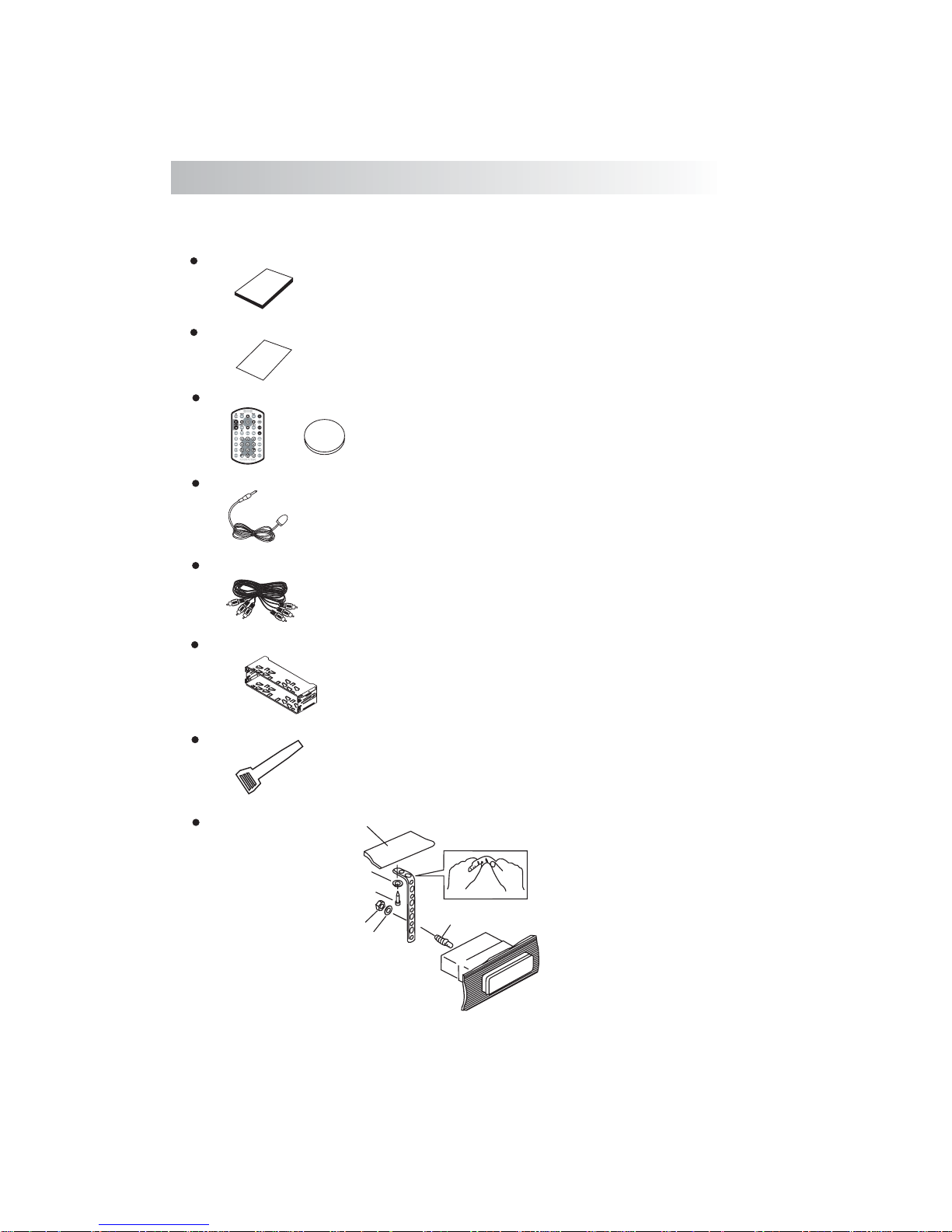
3.ACCESSORY INCLUDED
When first unpacking your new , please check first that the package
full detachable DVD head unit
contains all of the items below. If something is missing, contact the store where you purchased the
player.
Owner’s Manual
Warranty Card
Owner’s
manual
Warranty
Card
Remote control & Lithium Battery
0
2
2
R
5
C
+
3V
Extended remote control sensor jack & cable
Audio/Video cable
Half Sheeve
Insert Key
1. Dashboard
2. Nut (5mm)
3. Spring washer
4. Screw (4X12mm)
5. Screw
6. Support Strap
7. Plain washer
1
6
7
4
2
5
3
4
Page 6
Before finally installing the unit, connect the wiring temporarily and make sure it is all connected up
properly and the unit and system work properly.
Use only the parts included with the unit to ensure proper installation. The use of unauthorized parts
can cause malfunctions.
Consult with your nearest dealer if installation requires the drilling of holes or other modifications of
the vehicle.
Install the unit where it does not get in the driver's way and cannot injure the passenger if there is a
sudden stop, like an emergency stop.
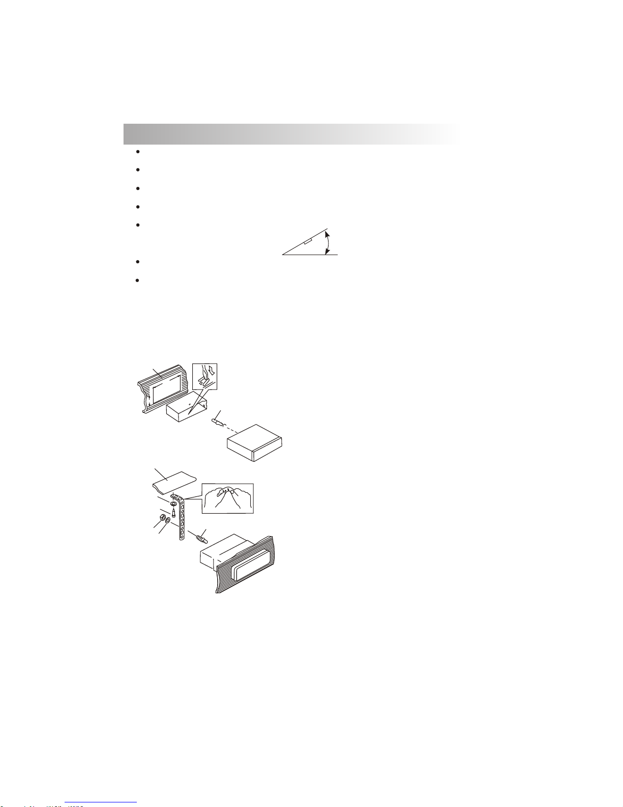
If installation angle exceeds 30° from horizontal, the unit might not give its optimum performance.
Avoid installing the unit where it would be subject to high temperature, such as from direct sunlight, or
from hot air, from heater, or where it would be subject to dust dirt or excessive vibration.
Be sure to remove the front panel before installing the unit.
DIN FRONT/REAR-MOUNT
This unit can be property installed either from “Front” (conventional DIN Front-mount) or “Rear”(DIN
Rear-mount installation, utilizing threaded screw holes at the sides of the unit chassis). For details, refer
to the following illustrated installation methods A and B.
DIN FRONT-MOUNT (Method A)
Installation the unit
1. Dashboard
2. Holder
After inserting the half sleeve into the
dashboard, select the appropriate tab
according to the thickness of the
dashboard material and bend them
inwards to secure the holder in place.
3. Screw
30°
1
7
4
2
3
5
6
1. Dashboard
2. Nut (5mm)
3. Spring washer
4. Screw (4X12mm)
5. Screw
6. Support Strap
Be sure to use the support strap to secure
the back of the unit in place. The strap can
be bent by hand to the desired angle.
7. Plain washer
182
53
1
2
3
4. INSTALLATION
5
Page 7
DIN REAR-MOUNT (METHOD B)
Installation using the screw holes on the sides of the unit.
Fastening the unit to the factory radio mounting bracket.
1. Select a position where the screw
holes of the bracket and the screw
holes of the main unit become
aligned (are fitted) and tighten the
screws at 2 places on each side.
2. Screw
3. Factory radio mounting bracket.
4. Dashboard or Console
5. Hook (Remove this part)
Note: the mounting box, outer trim ring,
and half-sleeve are not used for method
B installation.
5
2
4
3
2
5
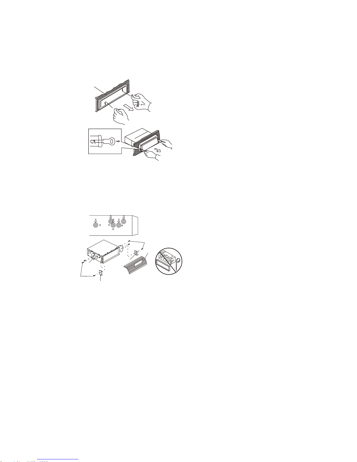
a. Frame
b. Insert fingers into the groove in the
front of frame and pull out to remove
the frame. (When re-attaching the
frame, point the side with a groove
down wards and attach it.)
c. Insert the levers supplied with the
unit into the grooves at both sides of
the unit as shown in figure until they
click. Pulling the levers makes it
possible to remove the unit from the
dashboard.
Trim Plate Installation:
Push the trim plate against the chassis until it is fitted.
You must do this before you install the front panel, otherwise it can't be attached.
Removing the unit
a
b
c
6
Page 8
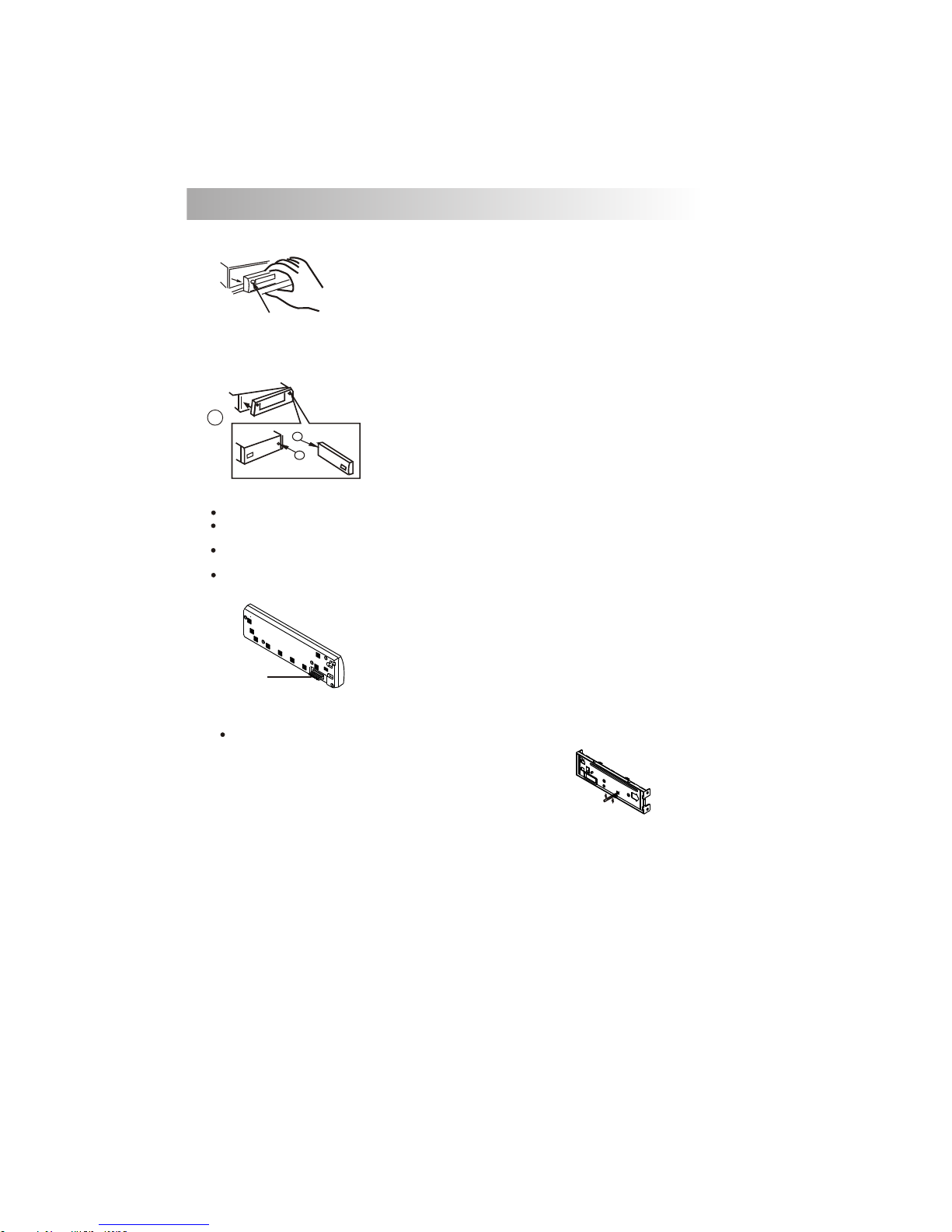
5. DETACHABLE CONTROL PANEL (D.C.P.)
Removing The Detachable Control Panel (D.C.P.).
1. Turn the power off
2. Press the D.C.P. release button
3. Remove the D.C.P.
PANEL RELEASE
BUTTON
B
A
2
Attaching the DCP
CAUTION
1. Attach the panel at the right side first, with
point B on the main unit touching point A on the
D.C.P. (As shown on the digram).
2. Then press the left side of D.C.P. onto the main
unit until a “click” sound is heard.
DO NOT insert the D.C.P from the left side. Doing so may damage it.
The D.C.P can easily be damaged by shocks. After removing it, place it in a protective case and be careful not to
drop it or subject it to strong shocks.
When the release button is pressed and the D.C.P is unlocked, the car's vibrations may cause it to fall. To prevent
damage to the D.C.P, always store it in a protective case after detaching it.
The rear connector that connects the main unit and the D.C.P is an extremely important part. Be careful not to
damage it by pressing on it with fingernails, pens, screwdrivers, etc.
Note:
If the D.C.P is dirty, wipe off the dirt with soft,
dry cloth only. And use a cotton swab soaked
in isopropyl alcohol to clean the socket on the
back of the D.C.P.
7
Socket
RESETTING THE UNIT:
After releasing the front panel, use a pencil or any non-metalic object to press & hold the
reset button for five seconds to reset the unit.
Page 9

6. WIRING DIAGRAM-AUDIO/VIDEO CONNECTIONS
HEAD PHONE
SUB
WOOFER
SUB-W OUT
DIGITAL OUT
SUB-WOOFER OUTPUT
2nd AUDIO OUTPUT
BLUE
BLACK
2nd AUDIO OUT
DIGITAL OUTPUT
EXTERNAL REMOTE JACK
ORANGE
PINK
REMOTE
VIDEO IN (1)
VIDEO (1) INPUT
YELLOW
AUDIO IN (1) R
AUDIO (1) INPUT (RIGHT)
AUDIO IN (1) L
AUDIO (1) INPUT (LEFT)
VIDEO OUT (1)
VIDEO (1) OUTPUT
VIDEO OUT (2)
VIDEO (2) OUTPUT
DOLBY DIGITAL
& DTS
DECODER
RED
WHITE
YELLOW
YELLOW
(Option)
VCR or DVD
or
GAME CONSOLE
FUSE
EXTERNAL REMOTE
RECEIVER
8
Page 10

AMP
RIGHT REAR
RIGHT FRONT
WHITE-BLACK LF
GREEN-BLACK LR
WHITE LF+
LEFT REAR
GREEN LR+
LEFT FRONT
GREY RF+
VIOLET RR+
VIOLET-BLACK RR
GREY-BLACK RF
RED
FUSE
YELLOW
BLACK
L-CH
R-CH
L-CH
WHITE
R-CH
RED
WHITE
RED
BLUE
20-PIN
AUDIO/POWER
HARNESS
ANTENNA
JACK
ANTENNA
EXTENDER
CABLE
(Not supplied)
GREY
FRONT
CHANNEL
1 2
3
4
5
6
7
8 9 10
11 12
13
14
15
16
17
18
19
20
Figure 1Pin View
20 PIN HARNESS PIN CHART
PIN WIRE COLOR FUNCTION / LABEL
1
2
3
4
5
6
7
8
9
10
11
12
13
14
15
16
17
18
19
20
GREY / BLACK
GREY
VIOLET
VIOLET/BLACK
PINK
GREEN
GREEN / BLACK
RED
BLACK
RED
WHITE
WHITE / BLACK
BLUE/WHITE
BLUE
YELLOW
BLACK
WHITE
RED
BLACK
WHITE
RIGHT FRONT SPEAKER ( )
LEFT REAR SPEAKER (+)
PARKING BRAKE ( )
LEFT FRONT SPEAKER (+)
POWER AMPLIFIER REMOTE (+)
CHASSIS GROUND
LEFT FRONT PRE-AMPLIFIER LINE OUT
LEFT REAR PRE-AMPLIFIER LINE OUT
LEFT FRONT SPEAKER ( )
POWER ANTENNA
BATTERY (+)
RIGHT FRONT PRE-AMPLIFIER LINE OUT
FRONT PRE-AMPLIFIER LINE OUT COMMON
RIGHT FRONT SPEAKER (+)
RIGHT REAR SPEAKER (+)
RIGHT REAR SPEAKER ( )
LEFT REAR SPEAKER ( )
IGNITION (ACC)
REAR PRE-AMPLIFIER LINE OUT COMMON
RIGHT REAR PRE-AMPLIFIER LINE OUT
(See Figure 1 )
POWER
AMPLIFIER
REMOTE
REAR
CHANNEL
BLACK
BLUE/WHITE
STRIPE
PINK
PARKING
BRAKE ( )
Connect to power amplifier, If not used,
Tape bare end of wire.
Power Antenna
Connect to power antenna or amplifier,
If not used, Tape bare end of wire.
Ground
Connect to ground terminal or clean
unpainted metal part of chassis.
Memory / Battery
Connect to battery or 12 volt power source
that is always live. The radio will not work if
this wire is not connected.
Accessory / Ignition
Connect to existing radio wire or radio fuse.
RCA-TO-RCA
CABLES
(Not supplied)
20 PIN AUDIO / POWER HARNESS
POWER ANTENNA/
AMPLIFIER REMOTE
GROUND
+12 VOLTS
CONSTANT
+12 VOLTS
SWITCHED
7. WIRING DIAGRAM - POWER / SPEAKERS (20 PIN)
9
Ground
Brake Switch
2.5m extension wire (optional)
Connect to Parking Brake.
EMPTY
N/A
Page 11

LO/DX
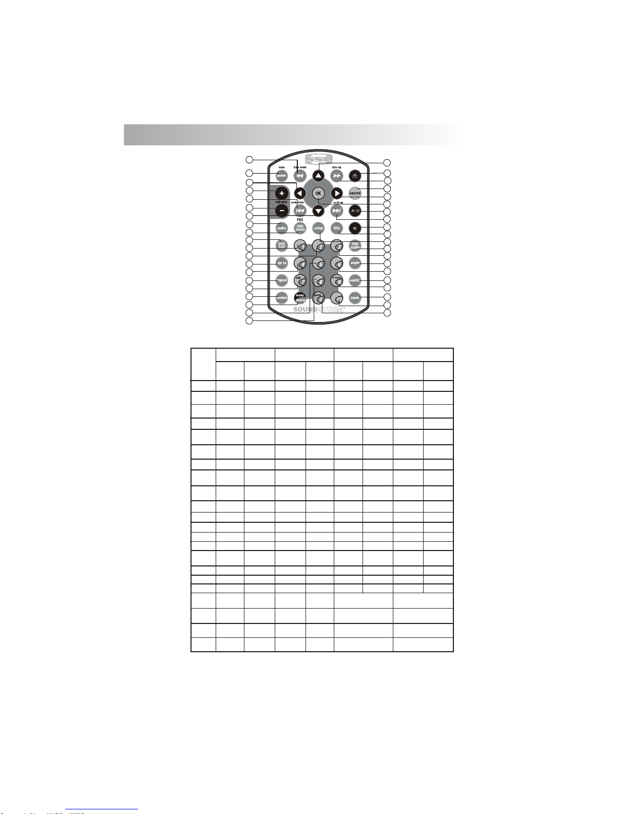
8. CONTROL PANEL FUNCTION
OPERATIONS:
10
12
13
14
15
10
20
1
4
5
18
3
17
16
11
21
2
22
DVD
KEY
SYSTEM TUNER CD/MP3 /WMA
1
2
Sou rce
PS
M1
M2
M3
M4
M5
M6
4
5
6
7
8
9
10
11
12
13
14
15
16
17
18
19
20
21
Dis play
See k Up
Pau se/Play
Fil e/Trac k
Up
Bac k
Nex t
Eje ct
3
Pan el Rele ase but ton
Ok
Fas t
For ward
Sho rt
Pre ss
Lon g
Pre ss
Eje ct
Enc oder
Volu me
AS
Memor y 1
Pau se/Play
Sho rt pres s M4
Men u
Tune U p
See k
Down
Tune
Dow n
Fil e/Trac k
Dow n
Pow er
Aud io
Men u
OSD
Band
Set -up
Set -up
Ok
Repe at Trac k
Rep eat Disc
Rep eat Off
Rep eat Cha pter
Rep eat Tit le
Rep eat Off
Sto p
Sto p
DVD Au dio
Pan el Rele ase but ton
Memor y 2
Memor y 3
Memor y 4
Memor y 5
Memor y 6
Fas t
For ward
Fas t
Bac kward
Fas t
Bac kward
Pan el Rele ase but ton
Sho rt
Pre ss
Lon g
Pre ss
Sho rt
Pre ss
Lon g
Pre ss
Sho rt
Pre ss
Lon g
Pre ss
Mut e
Sub -W
Ix- bass
Par king
Pan el Rele ase but ton
Ran dom
Fol der
Dimmer
DVD M enu
22
7
89
19
6
Eje ct
Page 12
OPERATIONS:
DVD
KEY
SYSTEM TU NER CD/MP3 /WMA
1
2
Mut e
M1
M2
M3
M4
4
5
6
7
8
9
10
11
12
13
14
15
16
17
18
19
20
21
Pau se/Play
22
Eje ct
Sho rt
Pre ss
Lon g
Pre ss
Eje ct
Mem ory
1
Pau se/Play
Pow er
Aud io
Men u
3
Sou rce
Volu me
Up
Fas t
For ward
Tune
Up
Tune
Dow n
Lef t
Rig ht
Up
Dow n
See k Up
See k
Dow n
Trac k Up
Trac k
Dow n
Nex t
Bac k
Ok Ok
Trac k NO. Acce ss
Trac k NO. Acce ss
Trac k NO. Acce ss
Trac k NO. Acce ss
Fil e NO. Acce ss
Num eric 1
Fil e NO. Acce ss
Fil e NO. Acce ss
Fil e NO. Acce ss
Num eric 2
Num eric 3
Num eric 4
Lef t
Rig ht
Up
Dow n
Sto p Sto p
9. REMOTE FUNCTION
Volu me
Dow n
Fas t
For ward
Fas t
Bac kward
Fas t
Bac kward
Mem ory
2
Mem ory
3
Mem ory
4
11
Sho rt
Pre ss
Lon g
Pre ss
Sho rt
Pre ss
Lon g
Pre ss
Sho rt
Pre ss
Lon g
Pre ss
DIMMER
RAN DOM
Lef t
Eje ct
1
9
10
5
15
6
13
3
30
34
35
32
19
20
22
25
23
40
12
8
2
4
11
14
17
16
18
37
31
26
21
38
24
39
36
27
33
7
28
29
Page 13

DVD
KEY
SYSTEM T UNER CD/MP3 /WMA
29
30
31
32
33
34
35
36
37
38
39
40
VCD : PBC
Set U p
OSD
go to
Sub title
Tit le
DVD
Aud io
Ang le
Zoo m
Set U p
DIS PLAY
DVD :
DVD M ENU
MEN U
Repe at Trac k
Rep eat Disc
Rep eat Off
Rep eat Cha pter
Rep eat Tit le
Rep eat Off
OPERATIONS:
27
28
Trac k NO. Acce ss
Trac k NO. Acce ss
Fil e NO. Acce ss
Fil e NO. Acce ss
Num eric 9
Num eric 0
iX- Bass
Ban d
M6
Trac k NO. Acce ss
Trac k NO. Acce ss
24
25
26
Trac k NO. Acce ss
Fil e NO. Acce ss
Fil e NO. Acce ss
Fil e NO. Acce ss
Num eric 6
Num eric 7
Num eric 8
Sub -W
12
M5
23
Trac k NO. Acce ss
Fil e NO. Acce ss
Num eric 5
Mem ory
5
Sho rt
Pre ss
Lon g
Pre ss
Sho rt
Pre ss
Lon g
Pre ss
Sho rt
Pre ss
Lon g
Pre ss
Sho rt
Pre ss
Lon g
Pre ss
Mem ory
6
Numeric +10
Trac k NO. Acce ss
Fil e NO. Acce ss
1
9
10
5
15
6
13
3
30
34
35
32
19
20
22
25
23
40
12
8
2
4
11
14
17
16
18
37
31
26
21
38
24
39
36
27
33
7
28
29
Page 14

8) SUB-WOOFER (SUB)
Press the SUB-W button to activate the Sub-woofer function On, and “Sub-woofer” will appear
on the LCD display for 3 seconds. press the SUB-W button again to turn off the Sub-woofer
Press this button to remove the control panel.
10. BASIC OPERATIONS
3) PANEL RELEASE BUTTON ( )
1) POWER ON/OFF BUTTON (POWER )
Press the POWER button or Short Press any other button on the front of the unit (except the
Open/Eject) to turn On the unit. Press the POWER button to turn Off the unit.
7) MUTE BUTTON (MUTE)
Short Pre ss the MUT E button t o mute the audio out put , and “ Mut e” will ap pea r on th e
display. P res s the mute button again to restore th e audio ou tpu t to th e previous le vel .
10) iX-BASS BUTTON (iX-Bass )
Press the iX-Bass button to turn on the IX-Bass function, and “iX-Bass” will appear in the LCD
display for 3 seconds. Press the iX-Bass button again to turn off the IX-Bass function
5) SOURCE BUTTON (SOURCE)
Short Press the SOURCE button to select a different mode of operation as indicated on the display
panel. Available modes include Tuner, DVD, AV IN-1.
13
18) DISPLAY (DISP)
Short Press the DISPLAY/MENU button repeatedly to select the following different Display options:
Spectrum mode 1 > Spectrum mode 2 > Spectrum mode 3 > Default Display.
Default Display
True S pect rum An alyz er mod e 1
True S pect rum An alyz er mod e 2
True S pect rum An alyz er mod e 3
The selected DISPLAY will appear in the display when the unit is turned on.
9) DIMMER BUTTON (DIM)
Press the DIMMER button to adjust the dimmer level.
This feature is used to designate the strength of the signals at which the radio will stop during
automatic tuning. "Distance" is the default, allowing the radio to stop at a broader range of
signals. To set the unit to select only strong local stations during automatic tuning,press this
button until "Local" appears in the display.
23) LOCAL / DISTANCE BUTTON(LOC)
6) ENCODER VOLUME BUTTON
To increase the volume, rotate the volume control knob clockwise. To decrease the volume, rotate
the volume control knob counter clockwise. When the volume is adjusted, the volume level is
shown on the display panel as a number ranging from 00 (lowest) to 46 (highest).
To Reset the DVD Setting
After releasing the front panel, use a pencil or any non-metalic object to press & hold the reset
button for five seconds to reset the main unit and the unit will return to the factory default settings.
IGNITION OFF CLOCK RECALL
The user can recall the clock time display by pressing the DISPLAY button, even when ignition is off.
RESET
To Reset the Main Unit System
Press SET UP button on remote control or long press AS/PS button to bring up
the SET UP Menu, select RATING then select DEFAULT, the DVD Setting will
resume to factory default value .
Page 15

Contrast
The contrast level of the display is set at "CONTRAST 05" by default. User can use the Volume Up
or Down button to adjust the contrast level from 00 to 10.
Clock Format
"CLK FORMAT 12H" is set as default.
User can use the Volume Up or Down button to choose the Time Format between “12 Hours” or “24
Hours”
18) MENU FUNCTION LIST (MENU)
Press & hold the DISPLAY/ MENU button for more than 3 seconds to access the menu. "Menu" will be
showed on appear on the display momentarily. User can navigate thru the menu items by pressing
the DISPLAY/ MENU button, or by pressing the Tuning Up or Tuning Down Buttons to access the next
or previous option. Once the desired menu items appears on the display, adjust that option by using
the Volume Up or Down button within 5 seconds. The following menu items can be adjusted as
described above:
Menu operations
Time Set
The time on the clock is set to 12:00 by default. User can adjust the time by using the Volume Up
button to adjust the minutes and Volume Down button to adjust the hours.
14
2 ZONE VERSION
Programmable Turn-on Volume (VOL PGM)
This option allows selection of the volume level , the radio will automatically assume when turning on.
"VOL PGM 12" is the default setting, which will turn on the radio at the volume level as adjusted in the
VOL PGM. To program a specific turn on volume level, use the volume control button to select
"VOLUME LEVEL” within 5 seconds.
Beep Tone
The beep tone feature allows the selection of an audible beep tone when a button is pressed. "BEEP
TONE On" is the default setting. Use the volume up/down button to select the "BEEP TONE Off" option
Page 16

11. AUDIO OPERATION
Short press “AUDIO“ button to access the Audio Menu. User can navigate thru the Audio Menu items by
pressing the / “AUDIO” button repeatedly, or by pressing the Tuning Up or Tuning Down Button. Once the
desired menu item appears on the display, adjust that option by using the Volume Up or Down button
within 5 seconds. The following menu items can be adjusted as described above. The unit will
automatically exit the Audio Menu after five seconds of inactivity.
Audio Menu
VOLUME (Volume Level)
User has 5 seconds to use the Volume button to adjust the desire volume level, the volume level
will be shown on the LCD display ranging from 00 (lowest) to 46 (highest).
BASS (Bass Level)
User has 5 seconds to use the Volume Up or Down button to adjust the desired Bass level range
from -6 to +6.
15
TREBLE (Treble Level)
User has 5 seconds to use the Volume Up or Down button to adjust the desired Treble level range
from -6 to +6.
BALANCE
User has 5 seconds to use the Volume Up or Down button to adjust the Balance between the
right and left speakers from R12 (full right) to L12 (full left). “C00” represents an equal balance
between the right and left speakers.
FADER
User has 5 seconds to use Volume Up or Down button to adjust the Fader between the front and
rear speakers from R12 (full rear) to F12 (full front). “C00” represents an equal balance between
the front and rear speakers.
12. TUNER OPERATION
19) BAND BUTTON (BAND)
Press BAND to change between FM bands and AM(MW) bands.
Manual Tuning
Press the Up Tuning( ) or Down Tuning ( )button for more than 3 seconds to move the
radio frequency number up or down by one step.
Auto Seek Tuning
Press the Up Tuning ( )or Down Tuning ( )button for less than 3 seconds to move to
next station automatically.
20&21) TUNING UP/DOWN BUTTON ( / )
12~17) PRESET STATIONS BUTTONS
Six numbered preset buttons store and recall stations for each band.
11) AUTOMATICALLY STORE / PRESET SCAN (AS/PS)
Automatically select 6 strong stations and store them in the current band. Select a band (if
needed). Press AS/PS button for more than three seconds. The new stations replace stations
already stored in that band.
Preset Scan
Scan stations stored in the current band. Select a band (if needed). Press AS/PS button for less
than 3 seconds. The unit will pause for ten seconds at each preset station. Press AS/PS button
again to stop scanning when the desired station is reached.
STEREO
The unit will automatically pick up a stereo signal when available. When in stereo mode, the ST
icon appears in the display. When no stereo signal is available, the unit will automatically revert to
mono operation, and no icon will be displayed.
Page 17
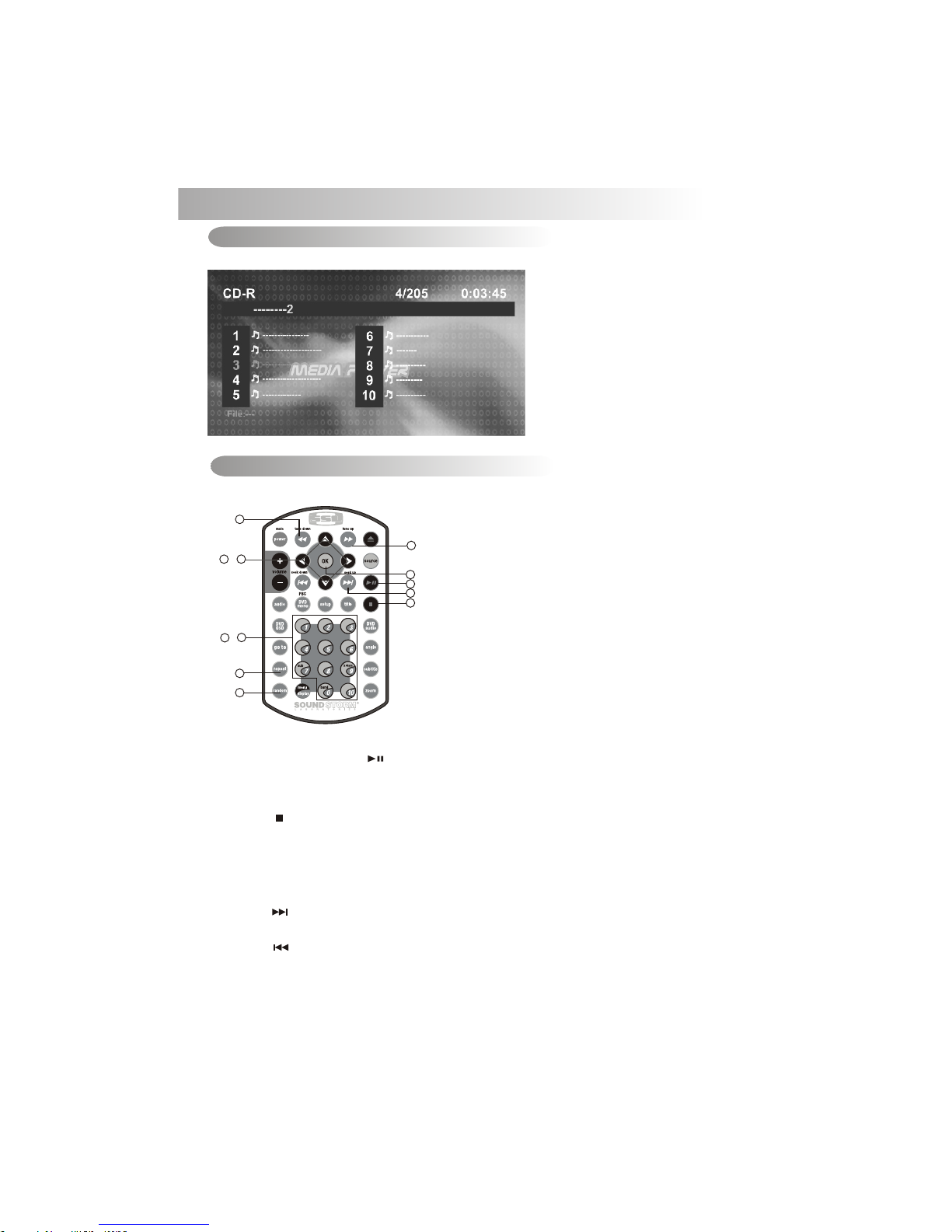
13. CD OPERATION
When a Audio CD is inserted into the player and the following picture will appear on the TFT monitor.
Audio CD Operation - Remote Control
17. Play/ Pause
18. Stop
8. Fast Forward
9. Fast Backward
14. Next
15. Back
19~29. Numeric buttons
32. Repeat
10~13. Up/Down/Left/Right button
16. OK button
7. Random
1. Press STOP to stop playback and show the logo screen. The player memorizes the location
where playback is stopped.
2. Press PLAY to resume playback from the location where playback is stopped (DVD,VCD 1.1,
VCD 2.0/SVCD/CVD and audio CD).
3. Pressing STOP twice is resume playback from the beginning of the disc.
18) STOP( )
To operates CD function through the following keys on the remote control.
Audio CD Operation - TFT Monitor
1. Press PAUSE to pause playback (still mode). The sound from the disc is muted during still
mode.
2. Press PLAY to resume normal playback.
17) PAUSE/ PLAY BUTTON ( / M1)
16
29
~
19
13
~
10
14) NEXT( )
Press NEXT to skip forward to the beginning of the next chapter.
Press BACK to skip backward to the beginning of the previous chapter.
15) BACK( )
9
8
14
17
16
18
7
32
Page 18

1. Press FAST FORWARD to fast forward through the disc. Each time the button is pressed,
a new speed (2X, 4X, 8X or 20X) is selected.
2. Press PLAY to resume normal playback.
3. Press FAST BACKWARD to fast reverse through the disc. Each time the button is
pressed, a new speed (2X, 4X, 8X or 20X) is selected.
4. Press PLAY to resume normal playback.
8~9) FAS T FOR WAR D& FAS T BACKWARD( o r )
19~29) NUM ERI C BUT TONS
1. When playb ack C D/MP3/WMA us e for t rack number or F ile n umber direct a cce ss and
use when func tio n need numeric S ele ction or Input , lik e in the Goto func tio n, etc.
2. Use when pla yba ck DVD whic h nee d numeric Sele cti on or Input, lik e in th e
Goto functi on, e tc
32) REPEAT
10~13) UP/ DOW N/L EFT/RIGHT BUT TON ( / / / )
Use to move cur sor u p/down/lef t/r ight.
16) OK BUTTO N
Use this butt on to c onfirm the sel ect ion.
17
The fast forward/backward speed may differ depending upon the disc.
7) RANDOM BU TTON
Press REPEAT button less than 3 seconds to “repeat play” the current song. And keep on repeat
Playing the current song until the “repeat play” is disabled. To disable current song “repeat
play”, press REPEAT button less than 3 seconds
Press RANDOM button less than 3 seconds is “random play” all songs on the disc. To disable all
file “ random play”, press RANDOM button less than 3 seconds.
Page 19

TRACK SELECT
Press the TRACK UP ( ) or TRACK DOWN ( ) button for less than one second to advance to the next
track on the CD, The selected track number will appear on the display. Press and Hold TRACK UP ( ) or
TRACK DOWN ( ) button for more than one second to fast forward or fast reverse through the disc. CD
play starts when the button is released.
1. Press PAUSE to pause playback (still mode). The sound from the disc is muted during
still mode.
2. Press PLAY to resume normal playback.
13) STOP BUTTON (STOP / M2)
14) REPEAT BUTTON (RPT / M3)
15) RANDOM BUTTON (RDM / M4)
12) PAUSE/ PLAY BUTTON ( / M1)
Audio CD Operation - Control Panel
The following function are avaiable operates through the control panel.
1. Press STOP to stop playback and show the logo screen. The player memorizes the location
where playback is stopped.
2. Press PLAY to resume playback from the location where playback is stopped (DVD, VCD 1.1,
VCD 2.0/SVCD/CVD and audio CD).
3. Pressing STOP twice is resume playback from the beginning of the disc.
18
When the last track playback completed, the unit will automatically enter into ‘STOP’ mode.
User can press play button to start the CD playback again when in the ‘STOP’ mode.
Press REPEAT button less than 3 seconds to “repeat play” the current song And keep on repeat
Playing the current song until the “repeat play” is disabled. To disable current song“repeat play”,
press REPEAT button less than 3 seconds
Press RANDOM button less than 3 seconds is “random play” all songs on the disc. To disable all
songs “ random play”, press RANDOM button less than 3 seconds.
12
13
14
15
Page 20
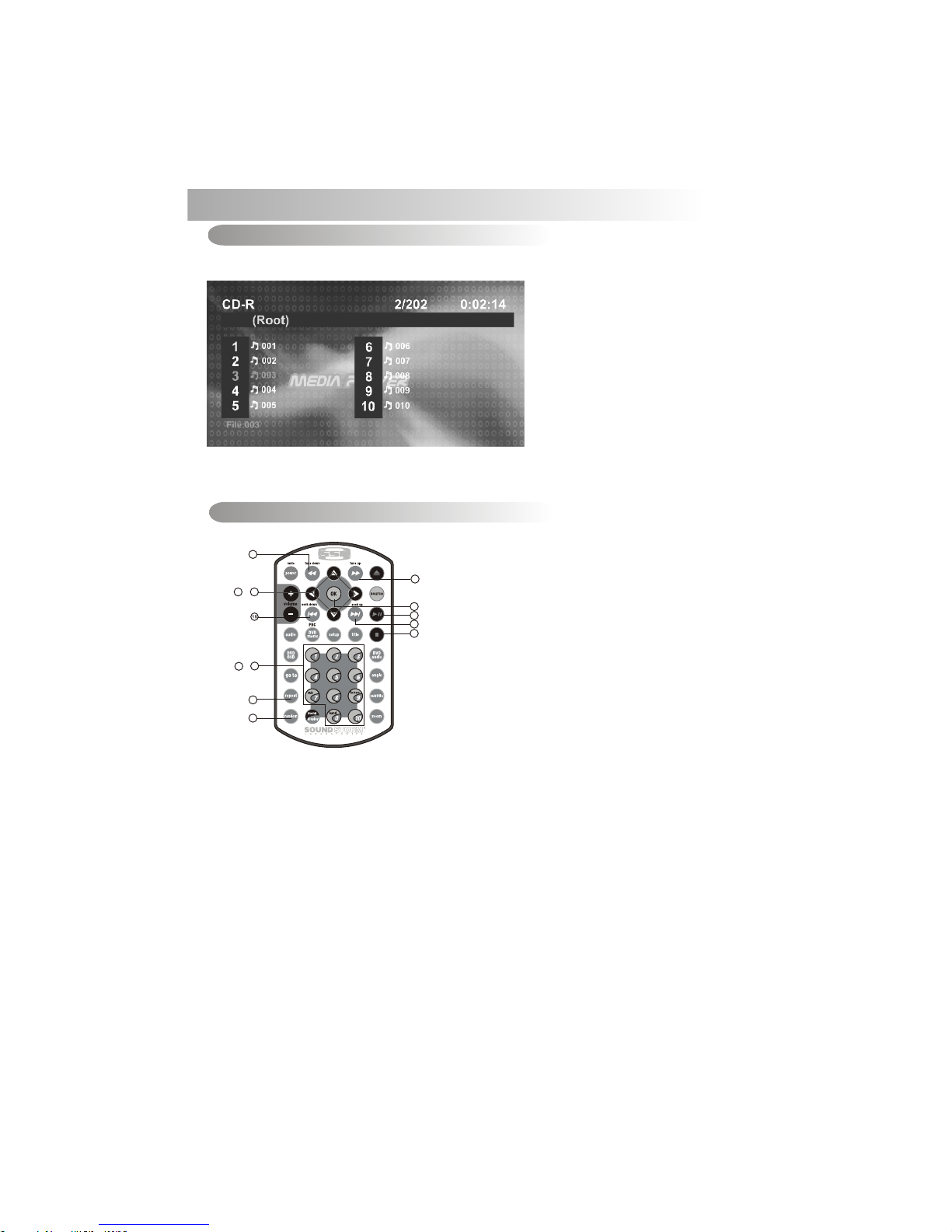
14. MP3/WMA OPERATION
MP3/WMA Operation-TFT Monitor
19
The player automatically plays the first track. The elapsed time within the track is displayed on the
right side of the top line. When the track is finished, the second track will begin playing, and the track
number on the top line will be updated. Press STOP to stop playback of the current file
When a MP3/WMA disc is inserted into the player and the following picture will appear on the TFT
monitor.
MP3/WMA Operation - Remote Control
17. Play/ Pause
18. Stop
8. Fast Forward
9. Fast Backward
14. Next
15. Back
19~29. Numeric buttons
32. Repeat
10~13. Up/Down/Left/Right button
16. OK button
7. RANDOM
To operates CD function through the following keys on the remote control.
Selecting a Track to Play
1. Use the UP/DOWN/LEFT/RIGHT direction buttons to move to different file numbers.
2. Press the RIGHT direction button when the highlighted file is in the column on the far
right, and up to five more file in the current directory will be displayed.
3. Press the LEFT direction button when the highlighted file is in the column to the far left,
and the previous five file will be displayed.
4. Press OK on a file number, and that file will begin to play, or by direct numeric input,
5. Enter a file number with the numeric buttons (0-9) and +10 button to play the input Files
Number.
8
14
17
16
18
9
7
32
29
~
19
13
~
10
Page 21

14) NEXT( )
Press NEXT to skip forward to the beginning of the next chapter.
Press BACK to skip backward to the beginning of the previous chapter.
15) BACK( )
1. Press FAST FORWARD to fast forward through the disc. Each time the button is
pressed,a new speed (2X, 4X, 8X or 20X) is selected.
2. Press PLAY to resume normal playback.
3. Press FAST BACKWARD to fast reverse through the disc. Each time the button is
pressed, a new speed (2X, 4X, 8X or 20X) is selected.
4. Press PLAY to resume normal playback.
8~9) FAS T FOR WAR D& FAS T BACKWARD( o r )
19~29) NUM ERI C BUT TONS
1. When playb ack C D/MP3/WMA us e for t rack number or F ile n umber direct a cce ss and
use when func tio n need numeric S ele ction or Input , lik e in the Goto func tio n,etc.
2. Use when pla yba ck DVD whic h nee d numeric Sele cti on or Input, lik e in th e Goto
function, etc
32) REPEAT
Press REPEAT button less than 3 seconds to “repeat play” the current file. And keep on repeat
Playing the current file until the “repeat play” is disabled. To disable current file “repeat play”,
press REPEAT button less than 3 seconds
10~13) UP/ DOW N/L EFT/RIGHT BUT TON ( / / / )
Use to move cursor up/down/left/right.
16) OK BUTTO N
Use this button to confirm the selection.
20
The fast forward/backward speed may differ depending upon the disc.
18) STOP( )
1. Press PAUSE to pause playback (still mode). The sound from the disc is muted duringstil
mode.
2. Press PLAY to resume normal playback.
17) PAUSE/ PLAY BUTTON ( / M1)
1. Press STOP to stop playback and show the logo screen. The player memorizes the
location where playback is stopped.
2. Press PLAY to resume playback from the location where playback is stopped (DVD,VCD
1.1, VCD 2.0/SVCD/CVD and audio CD).
3. Pressing STOP twice is resume playback from the beginning of the disc.
7) RANDOM BU TTON
Press RANDOM button less than 3 seconds is “random play” all files on the disc. To disable all file
“ random play”, press RANDOM button less than 3 seconds.
Page 22
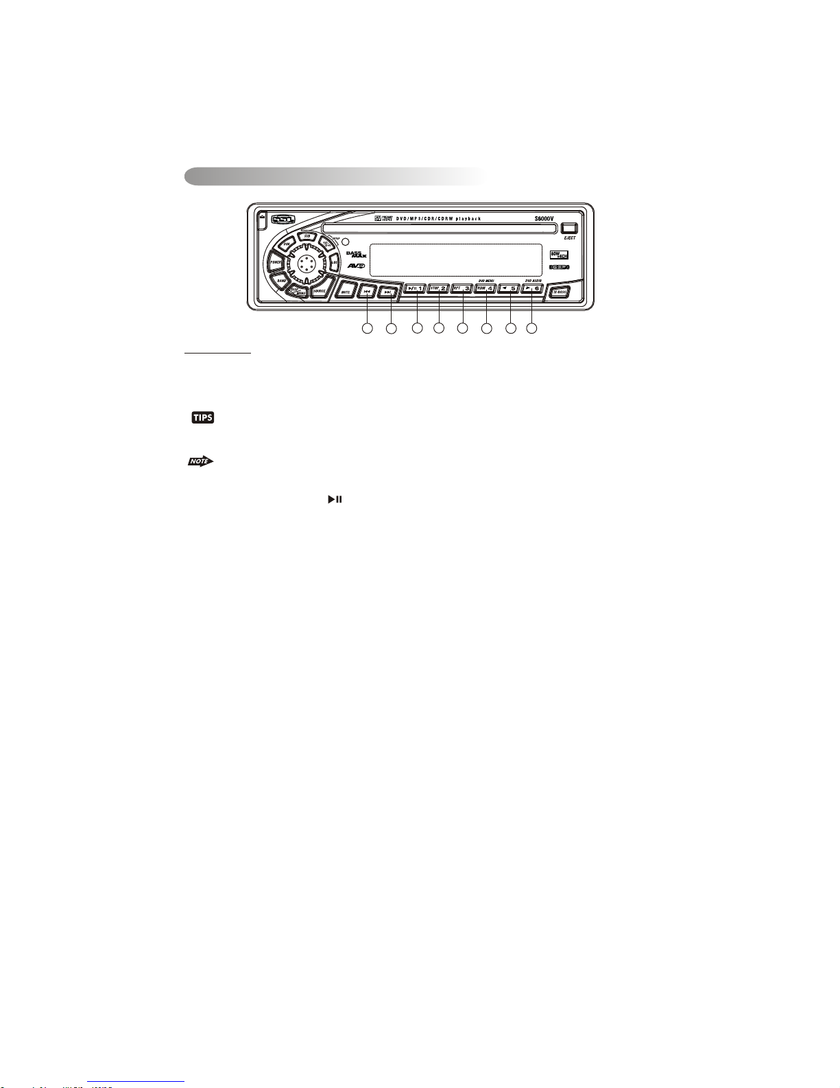
MP3/WMA Operation - Control Panel
The following function are avaiable operates through the control panel.
21
When MP3/WMA is playback, the M5 (16 ) use as LEFT direction button and M6 (17 ) use as
RIGHT direction. This is useful as navigate thru the LEFT page or RIGHT page which the
MP3/WMA interface displayed on the TFT monitor.
Press REPEAT button less than 3 seconds to “repeat play” the current file and keep on repeat playing
the current file until the “repeat play” is disabled. To disable current file“repeat play”, press REPEAT
button less than 3 seconds
Press RANDOM button less than 3 seconds is “random play” all files on the disc. To disable all files“
random play”, press RANDOM button less than 3 seconds.
FILE SELECT
Press the TRACK UP (20 ) or TRACK DOWN (21) button for less than one second to advance to the next
FILE on the disc, The selected file number will appear on the display. Press and Hold TRACK UP (20) or
TRACK DOWN (21) button for more than one second to fast forward or fast reverse through the disc.File
play starts when the button is released.
1. Press PAUSE to pause playback (still mode). The sound from the disc is muted during still
Mode.
2. Press PLAY to resume normal playback.
13) STOP BUTTON (STOP / M2)
14) REPEAT BUTTON (RPT / M3)
15) RANDOM BUTTON (RDM / M4)
12) PAUSE/ PLAY BUTTON ( / M1)
1. Press STOP to stop playback and show the logo screen. The player memorizes the location
where playback is stopped.
2. Press PLAY to resume playback from the location where playback is stopped .
When the last file playback completed, the unit will automatically enter into ‘STOP’ mode. User
can press play button to start the DISC playback again when in the ‘STOP’ mode.
12
13
14
15
20
17
16
21
Page 23

After inserting the DISC the player searches for and counts the files with appropriate formats (currently
only JPG, MP3 and WMA are supported).
OSD will show the message: “Searching for files… .” CD-R media and the number of files found will
appear over the logo background.
When the player has finished searching, it will automatically start Slideshow mode from the first
picture; all pictures will be displayed in their file/folder order. Default Slideshow interval between
pictures is five seconds. PAUSE, NEXT, BACK, and NUMERIC selection and navigation keys work the
same as in other operations.
22
1. Press the TITLE key to get a thumbnail view. Nine pictures (3x3) will be displayed on the screen,
beginning with the last viewed picture on the upper left part of the screen. The first thumbnail
image will be highlighted with a blue border.
2. Use the direction keys (LEFT/RIGHT/UP/DOWN) to select another thumbnail.
3. Use the NEXT/BACK keys to move to another thumbnails page.
4. Use the OK key to switch to the playback mode to start the image last highlighted in the thumbnail
view.
LOA DIN G AND D EFAULT PLAY BAC K
THUMBNAI L VIE W
15.JPEG CD Operation
Page 24
1. Press FAST FORWARD to fast forward through the disc. Each time the button is pressed, a
new speed (2X, 4X, 8X or 20X) is selected.
2. Press PLAY to resume normal playback.
3. Press FAST BACKWARD to fast reverse through the disc. Each time the button is pressed,
a new speed (2X, 4X, 8X or 20X) is selected.
4. Press PLAY to resume normal playback.
8&9) FAS T FOR WAR D& FAS T BACK FORWAR D( or )
Press BACK to skip backward to the beginning of the previous chapter.
14) NEXT( )
Press NEXT to skip forward to the beginning of the next chapter.
15) BACK( )
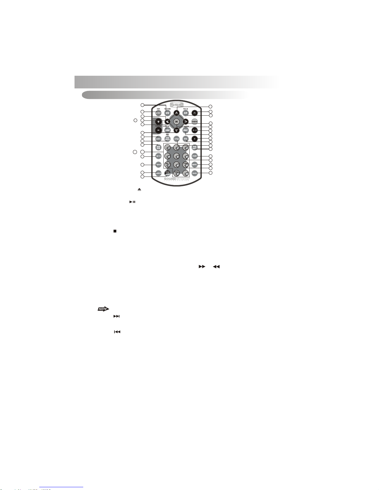
16. DVD OPERATION
2) EJECT BUTTON ( )
Press the EJECT button to eject the disc or loading the disc.
17) PLAY/PAUSE ( )
1. Press PAUSE to pause playback.
2. Press PAUSE to single step forward to the next picture in the video (DVD and VCD/SVCD
/CVD only).
3. Press PLAY to resume normal playback.
18) STOP( )
1. Press STOP to stop playback and show the logo screen. The player memorizes the
location where playback is stopped.
2. Press PLAY to resume playback from the location where playback is stopped (DVD,
VCD 1.1, VCD 2.0/SVCD/CVD and audio CD).
3. Pressing STOP twice is resume playback from the beginning of the disc.
DVD Operation - Remote control
23
The fast forward/backward speed may differ depending upon the disc.
10
13
~
19
29
~
Press REPEAT button less than 3 seconds to “repeat play” the current file. And keep on repeat
Playing the current file until the “repeat play” is disabled. To disable current file “repeat play”, press
REPEAT button less than 3 seconds
32) REPEAT
1
9
10
15
13
3
30
34
35
32
40
12
8
2
11
14
17
16
18
37
31
38
24
39
36
27
33
7
Page 25
10~13) UP/DOWN/LEFT/RIGHT BUTTON
Use these buttons to move cursor up/down/left/right.
16) OK
Use this button to confirm the selection.
19~29) NUM ERI C BUT TONS
30A) DVD MENU
1. Press DVD MENU to invoke the menu screen included on the DVD disc (DVD only).
2. Press direction buttons to highlight a selected menu entry.
3. Press OK or PLAY to select the highlighted entry. If the highlighted entry indicates a
chapter or title, the disc will play from the selected spot.
30B) PBC (Play back Control) (For VCD disc only)
1. Press DVD MENU to enable/disable PBC functionality with VCD 2.0/SVCD/CVD discs.
PBC must be enabled for menu navigation.
2. Press a number on the number pad to select a track to play(VCD 2.0/SVCD/CVD only).
3. Press OK to make the selection.
4. Press DVD MENU for the main menu.
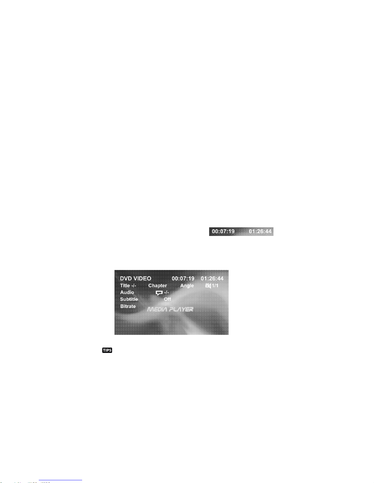
34) OSD BUTTON
1. Press OSD button once to display the amount of time played and time remaining to be
played on the disc. For example, the OSD may display:
24
2. Press OSD button a second time to additionally display the disc type, current chapter
(DVD) or track (VCD/SVCD/CVD, audio CD), and total number of chapters or tracks.
Also displayed (for DVD only) is the current title, total number of titles, audio language/
type/# of channels, subtitle language, and angle selection. For example, the OSD may
display:
Press OSD button in DivX file will display the file name, DivX version, file size and
frame rate.
3. Press OSD button a third time to make the OSD disappear.
1. When playb ack C D/MP3/WMA us e for t rack number or F ile n umber direct a cce ss and
use when func tio n need numeric S ele ction or Input , lik e in the Goto func tio n,etc.
2. When playb ack DVD use when f unc tion need nume ric S election or In put , like in the
Goto functi on, etc
Page 26

35) GOTO BUT TON
Using GOTO to Jump to a Specific Time, Chapter/Track, or Title
1. Press GOTO to enable the GOTO Menu. The OSD will display the following:
2. Press the UP/DOWN direction buttons to select the type of search: time search or
Chapter/track/title search.
25
Select “Time” to jump to a spot on the disc and enter the time in units of hours, minutes, and
seconds (hh:mm:ss):
Select "Title/Chapter" to jump to the beginning of a specific chapter within a specified title
(DVD only) and enter the title and chapter numbers with the number pad and LEFT/RIGHT
direction buttons, as follows:
Select "Track" to jump to the beginning of a specific track within a non-DVD disc and enter
the track number with the number pad, as follows:
1. Press ZOOM during normal, slow, or still playback.
33) ZOOM BUT TON
2. Pressing the ZOOM button repeatedly increases the magnification level. Three magnification
levels are supported. On each press of ZOOM, the OSD will flash the following:
3. Pressing the direction buttons causes the zoom point to shift, allowing the zoomed image to
be panned
37) TITLE
1. Press TITLE to invoke Title Menu (DVD only, dependent on authoring of disc).
2. Press direction buttons to highlight selected Title Menu entry.
3. Press OK or PLAY to select the highlighted entry. If the highlighted entry indicates a title, that
title will play from Chapter 1.
1) Some discs may not respond to the zoom feature.
2) Zooming does not work on subtitles or menu screens included on DVDs.
3) The magnification level and number of available levels vary, depending on the TV TYPE
selection in the Setup Menu.
Page 27

26
36) SUBTITLE
Press SUBTITLE during playback to turn on/off subtitles and to change the subtitles (DVD only).
The OSD indicates the current setting, giving the subtitle track number and the language selected,
for example:
1) The first press will show the current subtitle setting selected; subsequent presses
toggle to the next subtitle setting.
2) Some DVDs display subtitles automatically and cannot be turned Off, even if the
subtitle function is set to Off.
3) During some scenes, the subtitles may not appear immediately.
4) Some DVDs allow subtitle selections and turn subtitles on or off only via the disc menu.
5) When a disc is replaced, the Set Up returns to the default setting.
38) DVD AUDIO
Press DVD AUDIO during playback to change the audio language when playback a DVD disc.
The OSD indicates the current setting by giving the audio track number, language, audio type,
and number of channels. For example:
1) The first press shows the current language selected; subsequent presses toggle
the next audio language
2) Some DVDs allow audio selection change only via the disc menu.
3) When a disc replaced, the Set Up returns to the default setting.
Press ANGLE while playing a scene recorded with multiple angles to change the angle (DVD
only). The OSD indicates the current angle selected and the total available angles to select, for
39) ANGLE
1) The first press will show the current angle selected. Subsequent presses toggle to the
next angle.
2) The TFT monitor will light its angle icon when angle changes are available.
3) Some DVDs allow angle changes only via the disc menu.
4) When a disc is replaced, the Set Up returns to the default angle.
Page 28

DVD Operation - Control panel
Once a DVD disc is inserted into the unit, the unit will automatically start the playback from the beginning of
the disc, and then the DVD MENU or ROOT or TITLE in the DVD disc will appear on the TFT monitor and
“ROOT” will be displayed on the LCD of the unit.
27
12. PLAY/PAUSE ( M1)
1. Press PAUSE to pause playback.
2. Press PAUSE to single step forward to the next picture in the video (DVD and VCD/SVCD
/CVD only).
3. Press PLAY to resume normal playback.
13. STOP (/M2)
1. Press STOP to stop playback and show the logo screen. The player memorizes the
location where playback is stopped.
2. Press PLAY to resume playback from the location where playback is stopped (DVD, VCD
1.1, VCD 2.0/SVCD/CVD and audio CD).
3. Pressing STOP twice is resume playback from the beginning of the disc.
20. NEXT( )
21. BACK( )
20/21. FAST FORWARD & FAST BACK FORWARD ( or )
Press NEXT to skip forward to the beginning of the next chapter.
Press BACK to skip backward to the beginning of the previous chapter.
1. Long press FAST FORWARD to fast forward through the disc. Each time the button is
pressed, a new speed (2X, 4X, 8X or 20X) is selected.
2. Press PLAY to resume normal playback.
3. Long press FAST BACKWARD to fast reverse through the disc. Each time the button is
pressed, a new speed (2X, 4X, 8X or 20X) is selected.
4. Press PLAY to resume normal playback.
14. REPEAT (M3)
Press REPEAT button less than 3 seconds to “repeat play” the current file. And keep on repeat
Playing the current file until the “repeat play” is disabled. To disable current file “repeat play”,
press REPEAT button less than 3 seconds
15. DVD MENU (M4)
Under the DVD MENU or ROOT or TILTLE is display on the TFT Monitor. The buttons of Track up
/ down (20 / 21) use as LEFT / RIGHT direction button, Encoder Volume Knob (6) as UP / DOWN
direction button, and Audio(4) as OK button.
Press DVD MENU button less than 3 seconds to invoke the DVD MENU or ROOT on the DVD
disc.
Under the DVD MENU or ROOT or TILTLE is display on the TFT Monitor. The button of
Track up / down (20 / 21) use as LEFT / RIGHT direction button, Encoder Volume Knob (
6 ) as UP / DOWN direction button, and Audio button ( 4 ) as OK button.
12
13
14
15
20
4
17
11
21
19
6
Page 29

28
17. DVD AUDIO ( M6)
Long press DVD AUDIO button during playback to change the audio language (DVD only). The
OSD indicates the current setting by giving the audio track number, language, audio type, and
number of channels. For example:
The first press shows the current language selected; subsequent presses toggle the next
audio language
Some DVDs allow audio selection change only via the disc menu.
When a disc replaced, the Set Up returns to the default setting.
1. Press AS/PS once to display the amount of time played and tim remaining to be played on the
disc. For example, the OSD may display:
11. OSD (AS/PS)
11. Set up (AS/PS)
While the DVD disc is being played or under stop mode, the “SET UP” (AS/PS) button on the control
panel serve the following function:
Long Press “SET UP” (AS/PS) button to bring up the System Setup Menu
Please refer to the related description in “system Set Up” for details operation of “Set Up” !
After pressing the “Set Up” button, the LCD will display “Set Up” and keep on blinking. User
can use the following buttons to adjust the “Set Up” items shown on the TFT monitor as follow:
Encoder Volume Knob as Cursor to navigate thru the Set Up Items shown on the TFT Monitor.
Track Up / Down ( 20 / 21 ) buttons as Cursor Left / Right to navigate thru the Set Up items
shown on the TFT Monitor.
AUDIO button as ENTER to confirm the selected item shown on the TFT Monitor
Short Press “Set Up” button again or “Play” button to resume the DVD playback .
2. Press AS/PS a second time to additionally display the disc type, current chapter (DVD) or
track (VCD/SVCD/CVD, audio CD), and total number of chapters or tracks. Also displayed (for
DVD only) is the current title, total number of titles, audio language/ type/# of channels,
subtitle language, and angle selection. For example, the OSD may display:
Page 30

Press the SETUP button to invoke the Setup Menu. Pressing the SETUP button while the Setup Menu
is displayed will turn off the Setup Menu.
When the Setup Menu is invoked, the OSD will display the following row of text “buttons.” Each button
indicates a category of settings that can be changed:
Using the LEFT/RIGHT direction buttons, move to the Language button and press OK . The player's
Language settings will appear:
Language Settings
29
The LEFT/RIGHT direction buttons are used to select the category of settings to be changed. To
change a category, press OK and the page of settings for that category will be displayed.
When the category changes are set, press UP repeatedly to return to the text buttons. Selecting the
appropriate button and pressing OK can change settings in a different category.
1. Use the UP/DOWN direction buttons to select the setting to be changed.
2. Press OK to cycle through each possible option or display a list of the options. When a list of
options appears, press the UP/DOWN direction buttons to move among the displayed options.
3. Press OK again to choose the option and change the setting.
4. Press OK (after cycling through the options) to change the displayed value of the next available
option and change the setting.
1. DVD OSD Menu Language
Selecting the DVD OSD Menu setting allows the user to select a preferred language for the DVD
OSD menus and messages.
17. SYSTEM SET UP MENU
2. Preferred Subtitle language
Selecting the Subtitle setting allows the user to select a preferred subtitle language (DVD only).
Some DVDs may not include the pre-selected language. In this case, the player
automatically displays menus consistent with the disc's initial language setting.
Some DVDs may be set to display subtitles in a different language than selected.
Page 31

30
Selecting the DVD Audio setting allows the user to select a preferred audio language (DVD only).
The following options are available:
Some DVDs may be played in a different language than selected.
English = Audio preference is English
Chinese = Audio preference is Chinese
Selecting the DVD Menu setting allows the user to select a preferred DVD Menu language (DVD
only). The following options are available:
Some DVD menus may appear in a different language than selected.
English = DVD Menu preference is English
Chinese = DVD Menu preference is Chinese
Selecting the OSD setting allows the user to enable or disable the display of OSD status
messages during operation of the player. The following options are available:
On = Enable display of OSD status messages.
Off = Disable display of OSD status messages.
Divx Subtitle setting is used for choosing the language domain, (only for Divx). After select one
language domain (alphabet), when playback a divx with Divx subtitle, the subtitle display will use
this language alphabet. if you find the displaying subtitle “words” aren't correctly, please ensure
the external subtitle language and select the correct language. The following language domains
are available:
Western European = Include Albanian, Breton, Catalan, Danish, Dutch,
English, Faroese,Finnish, French, Gaelic, German,
Icelandic, Irish, Italian, Norwegian, Portuguese,
Spanish and Swedish.
Central European = Include Albanian, Croat, Czech, Dutch, English,
German, Hungarian,Irish, Polish, Romanian, Slovak,
Slovene and Sorbian.
Slavoic Cyrillic = Include Bulgarian, Belorussian, English, Macedonian,
Moldavian, Russian, Serbian and Ukrainian.
3. Preferred DVD Audio Language
4. Preferred DVD Menu Language
5. OSD Enabling/Disabling
6. Divx Subtitle
Page 32
31
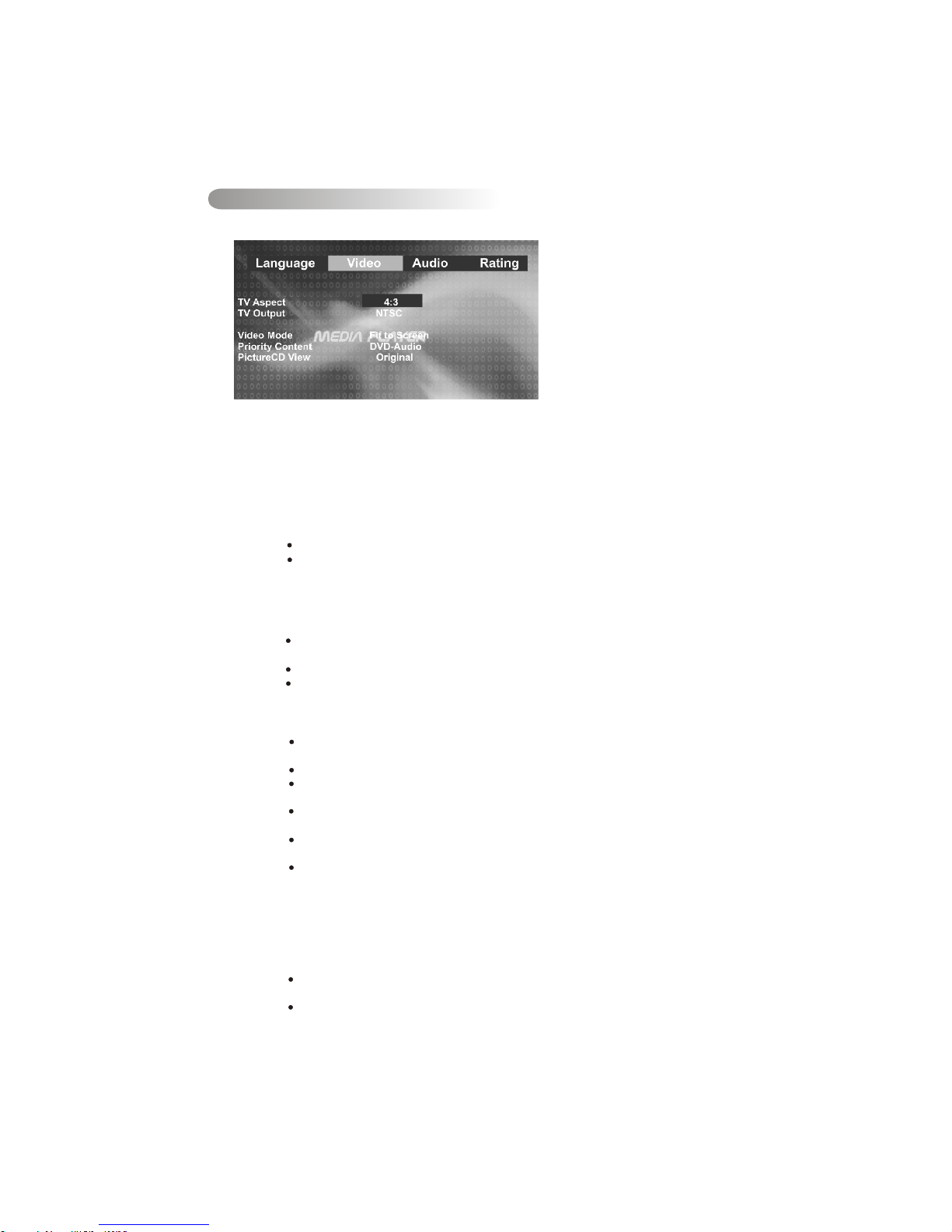
Using the LEFT/RIGHT direction buttons, move to the Video button and press OK. The Player's
Video settings will appear:
Use the UP/DOWN direction buttons to select the setting.
Press the OK to display a list of the options.
Press the UP/DOWN direction buttons to move among the displayed options.
Press the OK again to choose the option and change the setting.
The following subsections explain the available options for each of the player's Video settings.
Selecting the TV Aspect setting allows the user to select the aspect ratio of the TV (DVD and
VCD/SVCD/CVD only). The following options are available:
4:3 = Aspect ratio of TV is 4:3.
16:9 = Aspect ratio of TV is 16:9. Both widescreen and 4:3 contents will fill
the entire screen.
Selecting the Video setting allows the user to select the TV output (DVD and
VCD/SVCD/CVD only). The following options are available:
NTSC = TV is NTSC. PAL content is played at NTSC resolution and frame
rate (factory default).
PAL = TV is PAL. NTSC content is played at PAL resolution and frame rate.
Auto = If the content is PAL, the output is PAL. If the content is NTSC, the
Output is NTSC
Video Settings
1.
2.
3.
4.
5.
TV Aspect Ratio
TV Output (NTSC or PAL)
View mode
The user may select one of the following options:
Priority content
Picture CD View
Fill = Scale up/down the image in horizontal and vertical direction
respectively to fill the screen height and width.
Original = Fit the original screen size. (Only for Divx / MPEG)
H FIT = Height fit. Scale up/down the image in vertical direction to fit the
screen height, and keep the same scale ratio for horizontal.
W FIT = Width fit. Scale up/down the image in horizontal direction to fit
the screen width, and keep the same scale ratio for vertical.
Fit to Screen = Like letter box. Take the minimum value of horizontally fit
scale ratio and vertically fit scale ratio.
Pan Scan = Take the maximum value of horizontally fit scale ratio and
vertically fit scale ratio.
While with DVD Audio disk, the user may define if the priority is to play the Audio content or the
Video. The following options are available:
There are two options are available in Picture CD View.
Original = Used to switch the picture size to the current display resolution
Directly.
Fit to screen = Like letter box. Take the minimum value of horizontally fit scale
ratio and vertically fit scale ratio.
Page 33
32
Audio Settings
1.
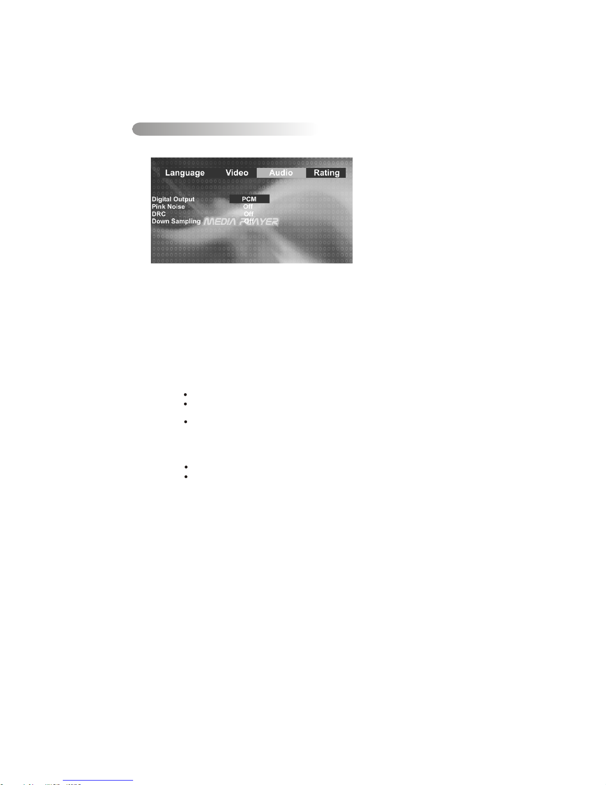
Using the LEFT/RIGHT direction buttons, move to the Audio button and press OK. The player's
Audio settings will appear:
3.
Press OK to display the player's Audio settings.
4.
Press UP/DOWN direction buttons to select the setting to change.
5.
Press OK to display a list of the option.
6.
Press UP/DOWN direction buttons again to move among the displayed options.
7.
Press OK again to choose the option and change the setting.
The following subsections explain the available options for each of the player's Audio settings.
2.
Press the LEFT/RIGHT direction buttons to select the Audio button.
Digital Output Setting
Selecting the Digital Output setting allows the user to adjust the audio output on S/PDIF
ports to work in harmony with the audio equipment (e.g. receiver, speakers) connected to
the player. The following options are available:
PCM = A S/PDIF output is connected to a receiver that accepts PCM S/PDIF.
Bitsteam= A S/PDIF output is connected to a receiver that accepts CDTS/ACS/
MP3/WMA/MPEG/PCM S/PDIF(factory defance)
Off = Digital audio output is disabled.
Dynamic Range Control setting
Selecting the DRC setting allows the user to enable/disable the DRC. The following options
are available:
On = DRC is On.
Off = DRC is Off (Factory default)
Page 34
33
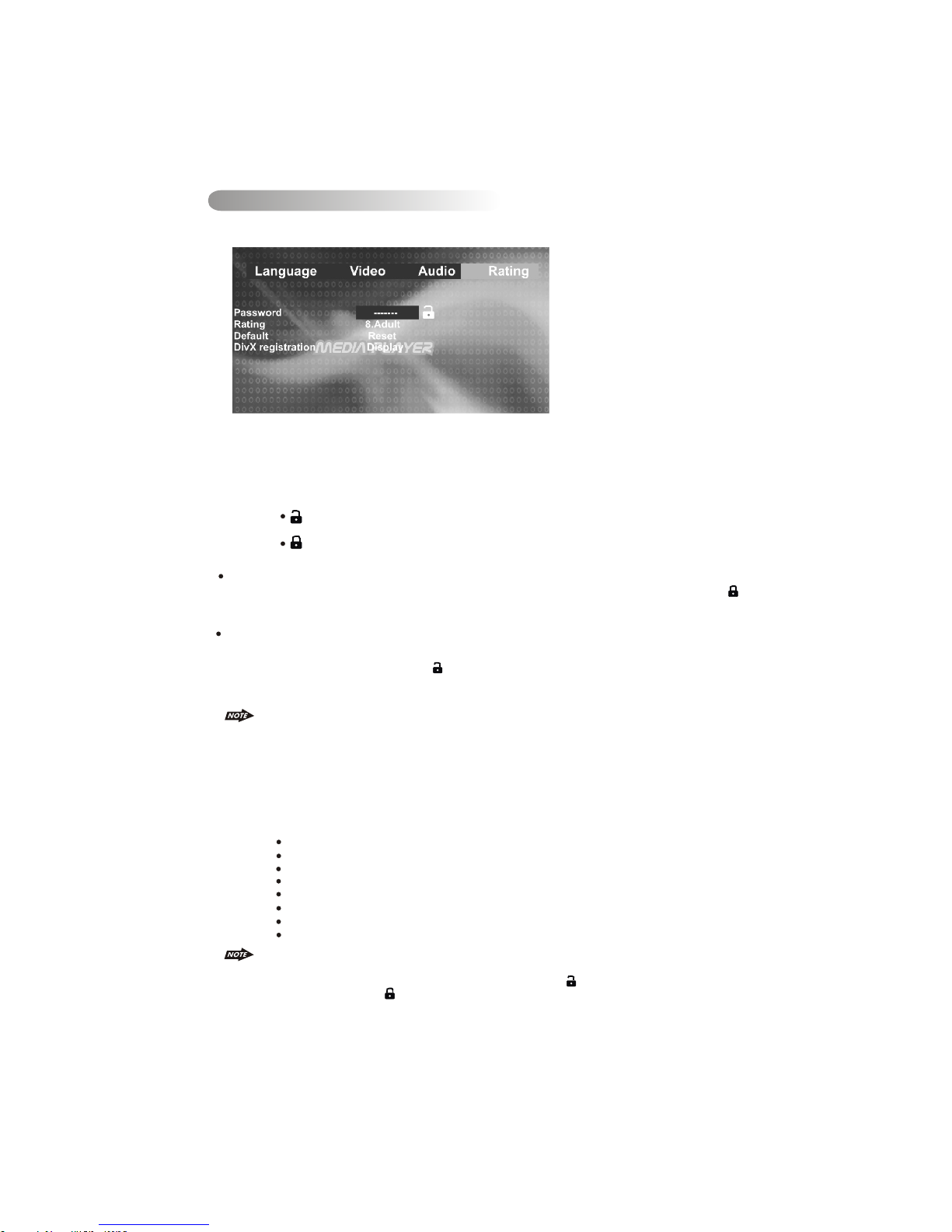
Rating Settings Change
1.
Using the LEFT/RIGHT direction buttons, move to the Rating button and press OK; the player's
Rating settings will appear:
2.
Use the UP/DOWN direction buttons to select the setting to be changed.
The following subsections explain how to change each of the player's Rating settings.
Password Selection to Lock and Unlock the Parental Control Rating
Selecting the Password Setting: Allows the user to enter a password, to lock and unlock the
parental control rating setting into the player. The following options are available:
(Unlocked) = The parental control is unlocked and may be changed in the
Rating selection (factory default)
(Locked) = The parental control is locked so no change may be made to the
Rating selection
Locking the Password: Enter four digits using the number keys. Each number entered is
overwritten by “ * ”. When all four have been entered, press the OK button. The “locked” icon (
) will appear, and the password is saved in non-volatile memory.
Unlocking the Password: Enter the four-digit password using the number keys. Each number is
overwritten by “ * ”. When all four ahve been entered, press the OK button.If the password was
entered correctly, the “unlocked” icon ( )will appear, and the password is erased from memory. If
the wrong password was entered no change will occur, and the user may attempt to enter the
password again.
1) A password is always four digits.
2) If the password is forgotten, the "back-door" password 8888 will unlock the parental
control.
3) See the explanation on Rating to see how locking and unlocking the password has An
effect on the parental control.
Parental Control Rating Selection
Selecting a Rating allows the user to set the parental control feature of the player. Press the OK to
cycle through the available options. The following options are available:
Kid Safe = Only titles with a parental control setting of 1 are allowed to play
G = Only titles with a parental control setting of 2 or less are allowed to play
PG = Only titles with a parental control setting of 3 or less are allowed to play
PG-13 = Only titles with a parental control setting of 4 or less are allowed to Play
PG-R = Only titles with a parental control setting of 5 or less are allowed to play
R = Only titles with a parental control setting of 6 or less are allowed to play
NC-17 = Only titles with a parental control setting of 7 or less are allowed to play
Adult = Allow any title to play (factory default).
1) Parental Control functions only if the DVD title has it encoded in its program. Parental control
does not work for VCD/SVCD/CVD or CD Audio.
2) Rating can only be changed if the password is “unlocked” ( ).Rating can not changed if the
password is “locked” ( ).
Page 35

18. Specification
DVD / CD Section
Compatible Disc/Format
Signal to Noise Ratio
Dynamic Range
Frequency Response
Channel Separation
Video Section
Color System
Video Output
Video Input
NTSC / PAL
Composite 1.0 Vp-p (+/- 0.2) 75 - ohm
Composite 1.0 Vp-p (+/- 0.2) 75 - ohm
Audio Section
Max Output Power
Load Impedance (speakers)
Digital Output
Line out level / load
Line out Impedance
80W x 4 channels
4 ohms
900mV
400mV / 10k ohm load
200 ohm
Auxiliary Input Section
Frequency response
Input Maximum Voltage
Input Impedance
20Hz to 20KHz -3dB
1200 mV
4.7k ohm
Radio Section
FM
Frequency Range
Usable Sensitivity
Stereo Separation
S/N Ratio
AM or MW
Frequency Range
Usable Sensitivity
S/N Ratio
522-1620 Khz (9 kHz Space)
< 40dB at S/N 20dB
40 dB
General
Operating Voltage
Grounding System
Fuse:
Operating Temperature:
Unit Mounting Angle
DC 11 -14.4V
Negative Ground
15-Amp Mini ATM Type
0°C to 50°C
< 30°
See “ Disc Note” for more details description
0 dB
20Hz to 20Khz +/-3dB
2 Channel (Stereo) >60dB @1khz
> 90 dB
> 9
87.5-108.0 MHz (50 kHz Space)
< 15dB at S/N 30 dB
25 dB at 1KHz
50 dB
34
Page 36
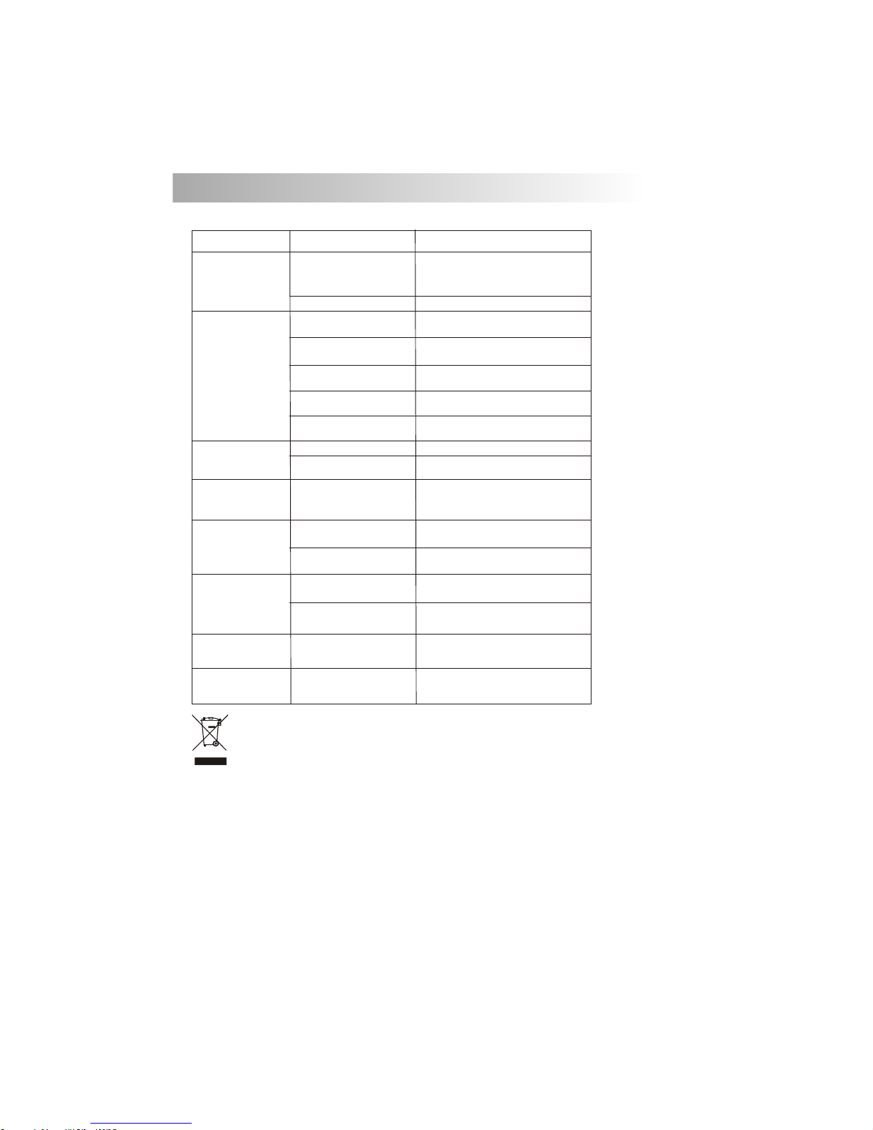
ERROR
Disc Error
Mechanism Error
Maybe disc dirty / disc scratched
/disc upside down.
Press the eject button to correct the problem.
If the error code does not disappear, consult
your nearest service dealer.
Replace the disc.
Symptom
Cause
Solution
No power
The car ignition is not on.
If the power supply is properly connected
to the car accessory terminal, switch the
ignition key to “ACC”
Disc cannot be
loaded or ejected
The fuse is blown.
Replace the fuse.
Presence of CD disc inside
the player.
Remove the disc in the player, then
put a new one.
Inserting the disc in reverse
direction.
Insert the compact disc with the
label facing upward.
Compact disc is extremely
dirty or defective disc.
Clean the disc or try to play a new one.
Temperature inside the car is
too high.
Cool off or until the ambient temperature
returns to normal.
Condensation.
Leave the player to off for an hour or so,
then try again.
Volume is in minimum.
Adjust volume to a desired level.
Wiring is not properly
connected.
Check wiring connection.
The operation keys
do not work
No sound
The built-in microcomputer is
not operating properly due to
noise.
Press the RESET button.
Front panel is not properly fixed into
its place
Sound skips.
The installation angle is
more than 30 degrees.
Adjust the installation angle to less
than 30 degrees.
The disc is extremely dirt or
defective disc.
Clean the compact disc. Then try to play a
new one.
The antenna cable is not
connected.
Insert the antenna cable firmly.
The signals are too weak.
Select a station manually.
The radio does not
work.
The radio station
automatic selection
does not work.
Before going through the check list, check wiring connection. If any of the problems persist
after check list has been made, consult your nearest service dealer.
19. TROUBLE SHOOTING
35
If at any time in the future you should need to dispose of this product please note
that Waste electrical products should not be disposed of with household waste.
Please recycle where facilities exist. Check with your Local Authority or retailer for
recycling advice.(Waste Electrical and Electronic Equipment Directive)
Page 37

 Loading...