

Page 1

User Manual
SD322B
BLUETOOTH® ENABLED
SINGLE DIN MOUNTING
DVD/MP3/CD AM/FM RECEIVER
3.2” DETACHABLE WIDESCREEN TFT MONITOR
USB and SD CARD PORTS and AUX INPUT
SD322B
BLUETOOTH® ENABLED
SINGLE DIN MOUNTING
DVD/MP3/CD AM/FM RECEIVER
3.2” DETACHABLE WIDESCREEN TFT MONITOR
USB and SD CARD PORTS and AUX INPUT
Page 2

SAFETY INFORMATION
This Digital Video Player Is A Class I
Laser Product. However This Digital
Video Player Uses A Visible/invisible
Laser Beam Which Could Cause .
Hazardous Radiation Exposure If
Directed.
Be Sure To Operate The Dvd Player
Correctly As Instructed.
Use Of Controls Or Adjustments Or
Performance Of Procedures Other Than
Those Specified Herein May Result In
Hazardous Radiation Exposure. do Not
Open Covers And Do Not Repair Y
ourself. Refer Servicing To Qualified
Personnel.
CAUTION:
This Digital Video Player is designed
and manufactured to respond to the
Region Management Information that is
recorded on a Digital Video disc. If the
Region number described on the Digital
Video disc does not correspond to the
Region number of this Digital V
ideo
Player, this Digital Video Player cannot
play this disc.
REGION MANAGEMENT
INFORMATION:
TO REDUCE THE RISK OF FIRE OR
ELECTRIC SHOCK, DO NOT EXPOSE
THIS EQUIPMENT TO RAIN OR
MOISTURE.
TO REDUCE THE RISK OF FIRE OR
ELECTRIC SHOCK, AND ANNOYING
INTERFERENCE, USE ONLY THE
RECOMMENDED ACCESSORIES.
THIS DEVICE IS INTENDED FOR
CONTINUOUS OPERA
TION.
WARNING:
This product incorporates copyright
protection technology that is protected
by method claims of certain U.S. Patents
and other intellectual property rights
owned by Macrovision Corporation and
other rights owners.
Use of this copyright protection
technology must be authorized by Macro
vision Corporation, and is intended for
home and other limited viewing uses
only unless otherwise authorized by
Macrovision Corporation.
Reverse engineering or disassembly is
prohibited.
Page 3

DISC NOTE
Preparing New Discs with Rough
Spots
A new disc may have rough edges on
its inside and outside edges.If a disc
with rough edges is used, the proper
setting will not be performed and the
player will not play the disc.Therefore,
remove the rough edges in advance
by using a ball point pen or pencil as
shown on the right.T
o remove the
rough edges, press the side of the pen
or pencil against the inside and outside
edges of the disc.
Rough spots
on
outside edge
Ball point pen
or pencil
Rough spots
on inside
edge
Label side
up
Do not touch
the
underside
of the disc
Do not
bend
Wipe the disc from
center
toward the outside
edge
Disc Cleaning
Use a dry soft cloth to wipe the surface.
If the disc is quite dirty, use a soft cloth
slightly moistured with isopropyl
(rubbing) alcohol. Never use solvents
such as benzine, thinner or conventional
record cleaners as they may mar the
surface of the disc.
Handling and Cleaning
Dirt, dust, scratches and warping disc
will cause misoperation.
Do not place stickers or make
scratches on discs.
Do not warp discs.
A disc should always be kept in its
case when not in use to prevent from
damaging.
Do not place discs in the following
places:
1.
Direct sunlight
2.Dirty, dusty and damp areas
3.Near car heaters
4.On the seats or dashboard
Discs which cannot be played
with this player
Digital Video-RAM
CDV
CD-G
Note:
A disc may become somewhat scratched
(although not enough to make it unusable) depending on your handling it and
conditions in the usage environment.
Note these scratches are not an indication of any problem with the player.
Disc formats supported by this
player
Digital
Video
VCD
CD
MP3
Audio and Video
Disc size 12 cm
Audio and Video
Disc size 12 cm
Audio
Disc size 12 cm
Audio
Disc size 12 cm
Digital
Video
VCD
CD
MP3
Page 4
NOTES:
Choose the mounting location where the
unit will not interfere with the normal
driving function of the driver.
Before finally installing the unit, connect
the wiring temporarily and make sure it
is all connected up properly and the unit
and the system work properly.
Use only the parts included with the unit
to ensure proper installation. The use of
unauthorized parts can cause
malfunctions.
Consult with your nearest dealer if installation requires the drilling of holes or
other modifications of the vehicle.
Install the unit where it does not get in
the driver
s way and cannot injure the
passenger if there is a sudden stop,
like an emergency stop.
'
30
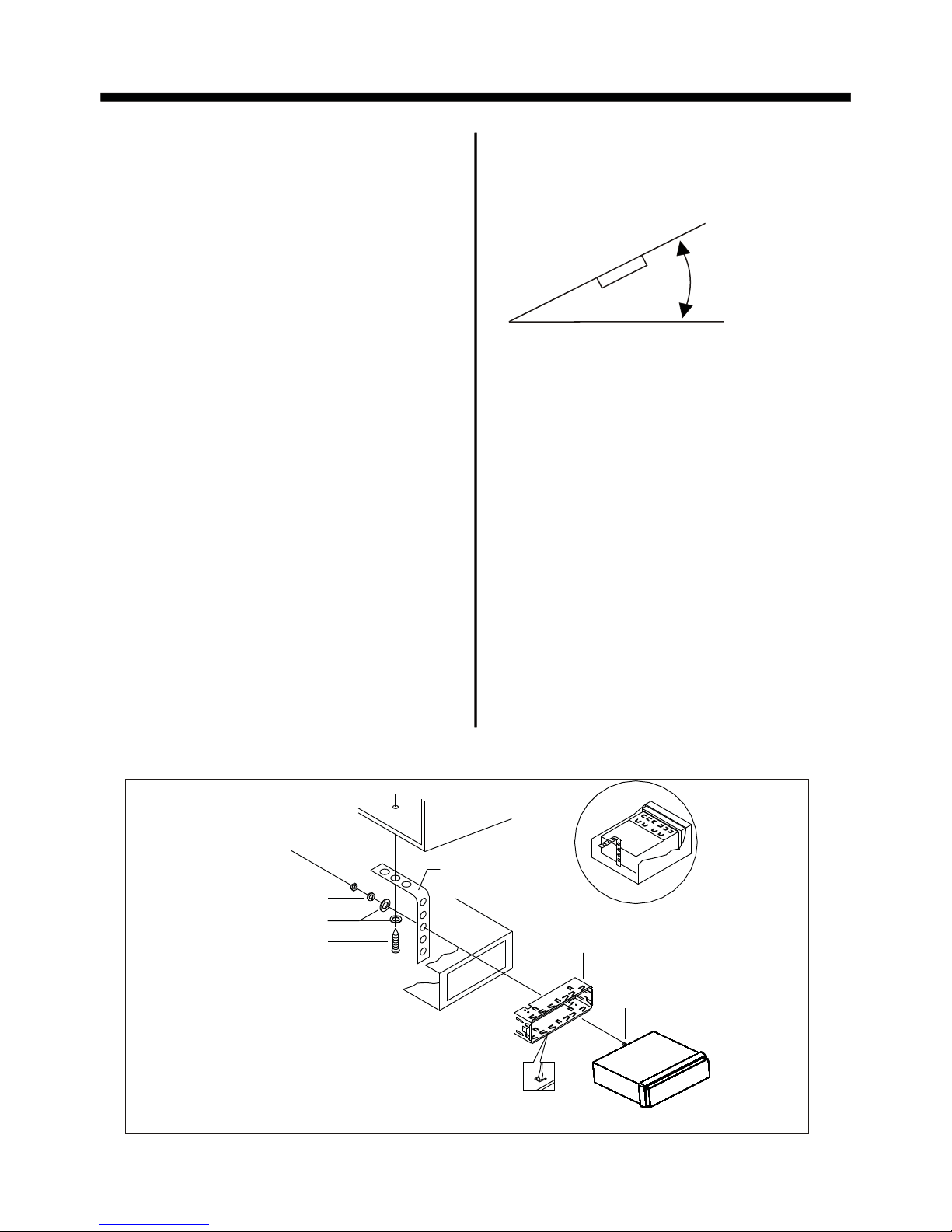
INSTALLATION
If installation angle exceeds 30 from
horizontal, the unit might not give its
optimum performance.
Avoid installing the unit where it would
be subject to high temperature, such
as from direct sunlight, or from hot air,
from the heater, or where it would be
subject to dust, dirt or excessive
vibration.
DIN FRONT/REAR-MOUNT
This unit can be properly installed either
from "Front"(conventional DIN Frontmount) or "Rear"(DIN Rear-mount
installation, utilizing threaded screw
holes at the sides of the unit chassis).
For details, refer to the following
illustrated installation methods.
DASH BOARD
METAL MOUNTING
STRAP
HEX NUT
SPRING WASHER
PLAIN WASHER
TAPPING SCREW
CONSOLE
SLIDE BRACKET
HOUSING
HEX BOLT
Page 5

INSTALLATION
DETACHING CONTROL PANEL
1. Press the OPEN button to flip down the
front panel .
2. First slide the front panel a little to
the right, and pull it off towards you .
OPEN button
3. put it in the protective case for safe
keeping.
PROTECTIVE CASE
FRONT PANEL
KEY PLATE
PLASTIC FRAME
KEY PLATE
If you want to take CHASSIS out of the SLIDE BRACKET HOUSING , first remove
the PLASTIC FRAME of the both sides away, then insert the two KEY PLATES into
left and right sides of chassis as above illustration.
Page 6

INSTALLATION
How to clean the connectors
Frequent detachment will deteriorate
the connectors.
To minimize this possibility, periodically
wipe the connectors with a clean, soft,
dry cloth only, being careful not to
damage the connectors.
Connector
ATTACHING CONTROL PANEL
1. First, insert the right side of the front
panel into the main unit.
Bulge
Hollow
Bulge
Hollow
3. Push it back to the position for playing
2. Push the right side of the front panel
until it locks firmly into the main unit, at
one time, insert the left side of the
front panel into the main unit .
Page 7
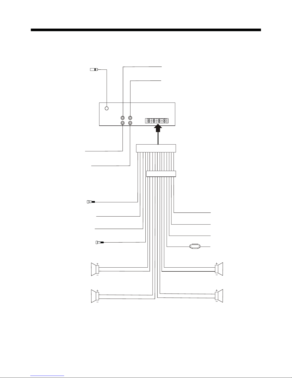
ELECTRIC CONNECTION
Note:
the earth connection cable (parking brake B-) must be connected in order for
pictures to be played back to the monitor. If the cable has not been correctly
connected, the message “PARKING BRAKE” appears on the monitor.
IGNITION SWITCH
RED
WHITE
WHITE/BLACK
GREY
GREY/BLACK
GREEN
GREEN/BLACK
VIOLET
VIOLET/BLACK
YELLOW
CONSTANT 12 VOLTS
BLACK
GROUND(B-)
BLUE
AUTO ANTENNA
FRONT
Lch SPK.
REAR
Lch SPK.
FRONT
Rch SPK.
REAR
Rch SPK.
BROWN
(B-) PARKING BRAKE
PINK
RADIO ANTENNA JACK
(B+) 12V
REAR CAMERA SWITCH
REAR CAMERA INPUT
YELLOW
GREY
SUB WOOFER
VIDEO IN (yellow)
AUDIO R OUT (red)
AUDIO L OUT (white)
VIDEO OUTPUT (brown)
WIRE CONNECTION
FUSE
ISO CONNECTOR
Page 8

REMOTE CONTROL
1. CLK Press it briefly to show the clock
time .
2. PAIR/ Press it to use the BT
function,refer to the BT operation
3. STOP Press once to pause playback,
press PLAY/PAUSE to resume playback .
4. SETUP Press it to open the SETUP
menu.
5.
MO/ST
(AUDIO) In radio mode, press it
to select STEREO or MONO mode (when
a station is weak, sometimes switching
to Mono will improve sound quality ) .
In Disc playback mode, pressing it button
opens the AUDIO setup menu for making
changes to the way te soundtrack is
reproduced .
6. LO/DX(SUBTITLE) Changing of the
SUBTITLE language on multi-subtitle
language Digital Video disc. In radio mode,
Press this button for distance reception
when you are located at weak signal
location, depress it for stronger signal.
7. REDIAL/ Press this button to use
the BT function, refer to BT operation.
8.GOTO/ Press this button to begin
playback at a moment in the program you
designate. Use the number buttons to
enter the data that is needed.
In BT phone menu, it serves as the
button on your mobile handset.
15
17
19
13
14
7
2
6
22
11
18
3
16
5
20
1
21
24
9
12
10
4
8
26
23
25
Page 9
REMOTE CONTROL
9. / Press to skip to the next
track & press to skip back one track.
BT
LOUD,
11 . VOL+/VOL- Press it to adjust
volume level .
12. / / / Use these buttons to
navigate the various menus present in the
product.
13. MENU/SUB WOOFER Press it to
display the root menu of the Digital V
ideo
disc. Press and hold this button to turn
ON or OFF the SUBWOOFER output.
14. BAND(OSD) In Radio mode, press
this button repeatedly to switch between
the five radio bands .
In Disc Playback modes, Press this
button to see information about the disc
currently in play
.
15.
/MOD Press this button to turn the
unit ON , press and hold to turn the unit
OFF. Press it briefly to select
16. PLAY/PAUSE ( ) In DISC mode,
starting playback, stopping picture/track.
17. MUTE Press this button to turn off the
audio. Press again to restore the sound
to its prior volume level.
18. TITLE/PBC (A/PS) Display the
TITLE menu which is recorded on the
. changing between PBC
ON and PBC OFF on the VCD disc.
In radio mode, press shortly to scan the
preset station, press longer to enter into
automatic memory storing function .
10. Briefly press to switch between
BASS, TREBLE, BALANCE, F
ADE,
COLOR, BRIGHTNESS, CONTRAST
,
TINT and VOLUME; Long press to display
, then briefly press to switch between
SUBWOOFER, EQ, LOCAL/DX
(in radio mode), STEREO/MONO(in
radio mode), CLK FMT
, SET CLK, FRE-
QUENCY AREA, ANIMA
TION and WALLPAPER. After selecting a item above,
use VOL+/VOL- button to adjust.
a desired
work source.
Digital Video
SEL
19. ZOOM Press this button to active
the ZOOM function . Each press of the
zoom button changes the screen in the
sequence : 2x 3x 4x ½ 1/3 1/4 .
Use the / / / buttons to move
through the zoomed picture .
Note : during the JPEG playback, press
the ZOOM button, the “ZOOM 100%” will
appear on screen, then press the /
button to increase/decrease in size,
use the / / / buttons to move
through the zoomed picture .
20. ANGLE Changing of the view angle
on multi-angle Digital V
ideo disc.
21. EQ/LOUD Press it briefly to turn to
equalization function. Press it longer to
switch the LOUDNESS function ON and
OFF .
22.
In DISC mode, Press to start forward
rapidly
.press
to reverse rapidly.
23. ENTER Confirm the Track/Chapter
selected with the number key or selected
with the cursor buttons on TV screen.
24. 0 - 9 These buttons are used for
numeric entry in many different menus.
In radio mode.
25. +10/ Tens digit select button,
cooperatively used with numeric buttons.
In BT menu, it serves as the
button on your mobile handset.
26. RADIO PRESET Six preset memory
buttons.
Page 10
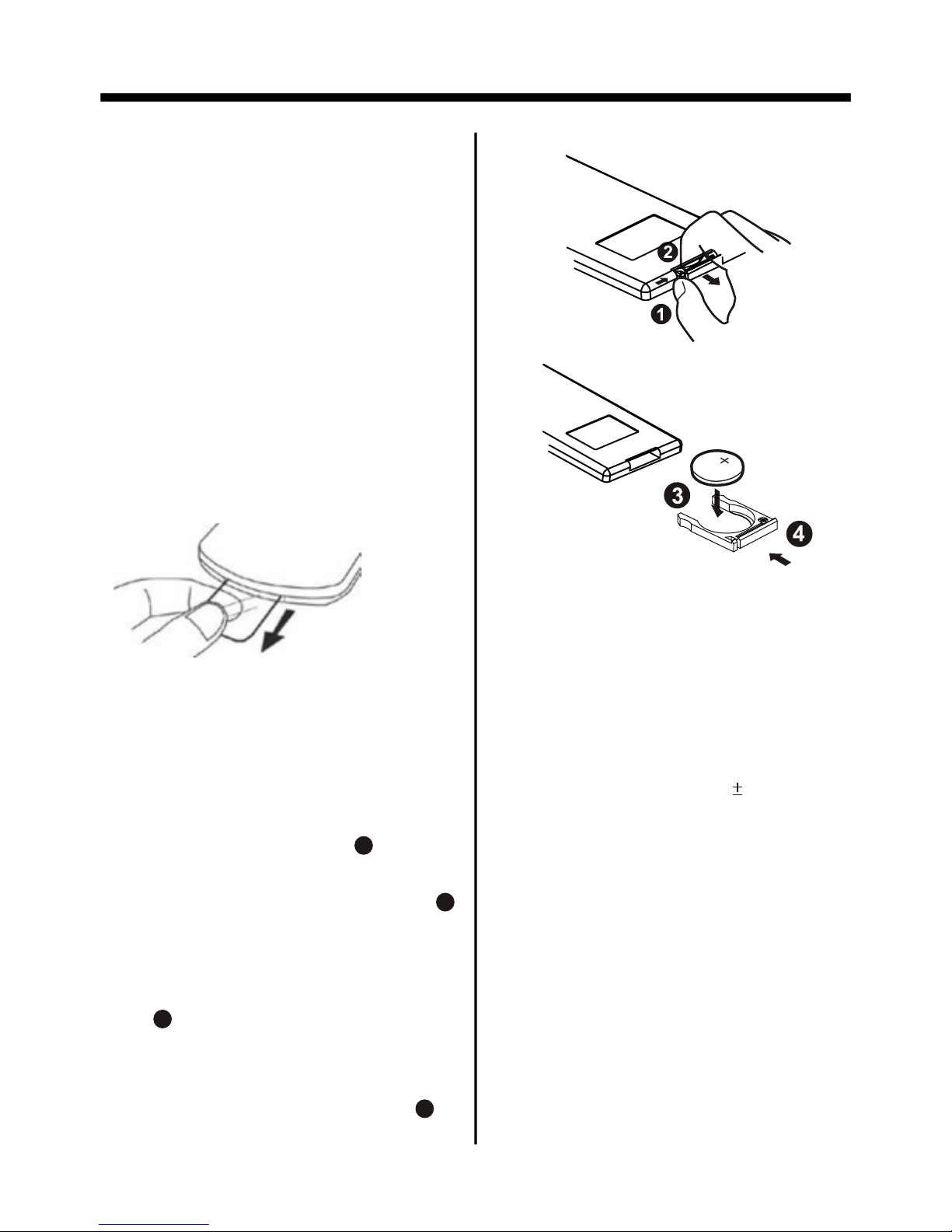
1. First push to inside as the direction
indicated by the arrow (See )and then
Remove the battery holder as the
direction indicated by the arrow (See ).
2. Replace the battery Set a new battery
property with (+)side up as illustrated
(See ).
3. Insert the battery holder. Push in the
holder to the original position(See ).
1
2
3
4
INSERTING THE BATTERIES
REMOTE CONTROL
PREPARING THE REMOTE
CONTROL
USING THE REMOTE CONTROL
1. Face the remote control towards the
player front face IR mark (remote control
signal receiver).
2. Operation angle: About 30 degree
in each the direction of the front of the
IR mark.
3. The distance between remote control
and sensor should not exceed 5M .
NOTE:
The lithium cell in the battery comp-
artment of remote control has been
secured for transport with a foil .
Before initial use please remove this
foil so that the remote control is ready
for operation .
WARNING :
Do not expose the batteries to high
temperatures or direct sunlight .
Never throw batteries into the fire, there
is a danger of explosion !
Page 11

BASIC OPERATION
1. OPEN Button
Press it to flip down the front panel , then
you can insert the CD disc into the CD
compartment. You can also press the
Eject button(13) to eject the disc.
1318 12
2. (POWER On/Off)/SRC Button
Press it to switch the device ON, press
and hold (approximately 2 seconds) to
switch the device OFF . During the
playback mode, you can press it to select
an input mode by pressing repeatedly
until proper one is found:
>RADIO >DISC >USB > CARD >AUX IN
>BT MUSIC >
Control Panel
Control Panel
Base of Control Panel
3. VOL Multifunction Button
In normal mode, this button is used to
increase or decrease the volume.
If the SEL button is pressed beforehand,
changes can be made in the menus,
e.g. Sound mode .
4. utton
Briefly press to switch between BASS,
TREBLE, BALANCE, FADE, COLOR,
BRIGHTNESS, CONTRAST, TINT and
VOLUME; Long press to display BT
, then
briefly press to switch between LOUD,
SEL B
14
2
1
15
17
8
16
3
7
6
11
4
10
9
5
1920
Page 12

BASIC OPERATION
8. CH 1-6
(RADIO PRESET) or
A). In Disc Playback Mode
Press this button to pause playback,
press it again to resume playback.
7.MUTE Button
Press this button to turn off the audio.
Press again to restore the volume to the
prior level. Yo u can also disable the
MUTE function by turning the VOL +/knob.
6. EQ Button
Press the EQ button briefly to turn to
equalization function and to select
desired audio mode.
There are five kinds of mode as below:
Press it longer to switch the LOUDNESS
function ON and OFF .
JAZZ CLAS POP ROCK USER
5. BAND/ Button
In Radio mode, press this button repeatedly (or the BAND button on the remote
control) to cycle through and select the
desired radio band, the designation of
the corresponding level- FM1, FM2,
FM3, AM1(MW1), AM2(MW2)- is shown
in the TFT.
B) In Radio Mode
you can store 30 stations in memory:
18 FM stations and 12 AM(MW) stations,
each band stores up to six preset
stations .
The operation as below :
-Store in Memory
> Select the frequency band
> Press repeatedly the button to select
the desired memory key .
> Select the station
> Keep the desired memory key pressed
in until the station is heard again after
a brief interruption .
-Retrieve a preset station
press the button repeatedly to retrieve
a station which had been stored in the
memory in advance the chose number
is shown on display .
9/10 . / Buttons
(tune, Seek, Track, Skip Up/down)
a) In DISC, USB mode:
if you wish to jump forwards or back wards press briefly the or button.
Press and hold up for more than two
seconds to begin Fast Forward (or down
for Fast Reverse) mode. Press the
button again as needed, to cycle thru the
range of available speeds.
Digital Video/VCD/CD/MP3:
Normal Playback 2x 4x 8x 20x
b) In Radio Mode:
Press the or button
to start the
search for a radio station
briefly to manually tune the radio in single steps. Press
and hold for two seconds
automatically.
SUBWOOFER, EQ, LOCAL/DX(in radio
mode), STEREO/MONO(in radio mode),
CLK FMT, SET CLK, FREQUENCY AREA,
ANIMATION and WALLPAPER. After
selecting a item above, use VOL knob to
adjust.
Page 13

BASIC OPERATION
12. (EJECT) Button
In DISC playing ,Press the Open button
(1) to flip down the front panel, then you
can press the this button to eject the disc .
14. IR (Infrared)
Sensor for the remote control .
13. RESET Button
RESET button is placed on the housing
and must be activated with either a
ballpoint pen or thin metal object. The
RESET button is to be activated for the
following reasons:
A. Initial installation of the unit when all
wiring is completed.
B. All the function buttons do not operate.
C. Error symbol on the display
.
11. PAIR/ Button
In BT menu, press this button to
use the BT function, how to use
it , please refer to BT operation
19. MIC ( Microphone position )
15. AUX INPUT JACK
For information about using an AUX IN
audio source, refer to AUX operation.
16. TFT Display
(liquid crystal display)
The operation of the TFT, refer to TFT
Monitor Adjustment
17. USB PORT
For information about connecting a
USB device, refer to USB operation.
18. SD/MMC CARD SLOT
For information about connecting a
SD card device, refer to SD/MMC Card
operation.
20. APS Button
For the function of the APS button,
please refer to the part of the Radio
Operation.
Page 14

BASIC OPERATION
TFT MONITOR ADJUSTMENT
In disc playing , press the “SEL” knob
on the front panel to adjust the Audio/
Video item, using the VOL+/- knob to
adjust, the message will display on the
screen like following below:
REAR VIEW CAMERA
When connecting the rear view camera.
the mirror image of the rear view through
the rear view camera is automatically
displayed on the monitor when you
change
the gear to the back position.
(Note : additional the monitor can not
display image .)
CONTRAST: 0 to 32
Adjust the contrast of the bright and dark
portion.
TINT: 0 to 32
Adjust the tint if the human skin color is
unnatural.
-Adjustable when “NTSC “ is selected for
“NTSC/P
AL “
.
ADJUSTABLE ITEMS:
COLOR: 0 to 32
Adjust the color for the picture-lighter or
darker.
BRIGHT: 0 to 32
Adjust if the picture is too bright or
too dark.
FADE: F 0-10 to R 0-10
Adjust sound balance between front and
rear speakers .
TREBLE: -7 to +7
Adjust treble level .
BALANCE: R 0-10 to L 0-10 .
Adjust sound balance between left
and right speakers .
BASS: -7 to +7
Adjust bass level .
VOLUME: 0 to 40
Adjust volume level .
SETTING AUDIO MODE
In any mode , longer press “SEL” button
on the front panel, the “LOUDNESS ON”
will display, then repeatedly press
shortly to select the other items, using
the VOL+/- knob to adjust, then press
the SEL to confirm the setting.
the message will display on the screen
like following below:
ADJUSTABLE ITEMS:
LOUDNESS ON/OFF
SUBWOOFER ON/OFF
DX/LOCAL:in radio mode
STEREO/MONO: in radio mode
ROCK
use the VOL+/- to choose the equalizer
mode: USER, JAZZ, CLASSIC, POP,
ROCK.
Page 15

BASIC OPERATION
Note:
Please set the playing time of the animation to “ 10S ” for the first, when you
turn the unit on .
Only in the RADIO mode, Longer (more
than 2’s) press the SEL button and then
shortly press it to select the Animation
item, then you can use the VOL+/- knob
to change the playing time of animation
among “OFF
, 10S, 30S, 1M, 1.5M,2M,
3M and 4M ”.
ANIMATION
In any modes, longer (more than 2’s)
press “SEL” button and then repeatedly
press shortly it to select the Background
Color item, use the VOL+/- to change
until choose your desired Background
Color . E.X: In RADIO mode :
SETTING BACKGROUND
in wallpaper mode, you can select the
among of “Pink, Blue, Light Blue, Red,
Yellow, Green, Auto ” .
When you select the “AUTO” item, the
player will change the background color
automatically .
24H CLOCK FORMAT
use the VOL+/- to choose clock display
in 12 or 24 hour.
SET CLOCK 06:36
Rotate VOL+/- knob clockwise to adjust
the hour and anticlockwise to adjust the
minute and confirm the setting by pressing the SEL knob.
USA/EUR FREQUENCY
use the VOL+/- to choose the USA or
EUROPEAN frequency
.
ANIMA
TION 10 SECONDS
use the VOL+/- to choose the animation
playing time.
WALLPAPER PINK
use the VOL+/- to choose the background color
.
The RESET button is to be activated for
the following reasons:
A. Initial installation of the unit when
all wiring is completed.
B. All the function buttons do not operate.
C. Error symbol on the display
.
Reset Factory Settings
RESET button is placed on the housing
and must be activated with either a
ballpoint pen or thin metal object.
RESET
BT ON/OFF
To switch the BT function on/off.
LOC ST USER
101.60
FM2 MH2
1
87.50
2
90.10
3
98.10
4
105.30
5
106.20
6 88.20
WALLPAPER PINK
LOC ST USER
101.60
FM2 MH2
1
87.50
2
90.10
3
98.10
4
105.30
5
106.20
6 88.20
ANIMATION 10SEC
Page 16

BASIC OPERATION
When an FM stereo broadcast is
hard to receive
Press ST/MO button on the remote
control to select the MONO or STEREO
mode . (When Stereo mode is activated,
the ST symbol will appear . )
Selecting The Frequency Band
Repeatedly press the BAND button on
the front panel to select the band, the
message will show in turn :
FM1 FM2 FM3
AM2(MW2)
AM1(MW1)
RADIO OPERATION
Press the MODE button to select the
RADIO mode, the message will like
following below :
Start Searching For a Station
During Radio mode, briefly press the
button on the front panel to increase
frequency by one step of channel
spacing . (Or you can press button
on the remote control)
Manual Search
During Radio mode, briefly press the
button on the front panel to decrease
frequency by one step of channel
spacing . (Or you can press button
on the remote control)
Automatic Search
During Radio mode, press and hold
(for more than 2’s ) the “ / ” button
to start search for a radio station
automatically .
You can use the “ / ” buttons on the
remote control to start search for a radio
station automatically .
To tune in strong-singnal FM
Station only (LO/DX function)
Press the LOC/DX button on the remote
control to choose between the LOC and
DX mode of Local and Long-distance
traffic news . The word “LOC” or “DX”
will display in the screen .
Storing Stations In Memory
Setting Memory
With this system, a total of 30 stations
can be stored in the memory of six
buttons. Each band stores up to six
preset stations. The stations might be
FM1, FM2, FM3, AM1(MW1), and
AM2(MW2) band.
The operation is as below :
- Store in Memory
>Select the frequency band
>Select the station
>Keep the desired memory key pressed
in until the station is heard again after
a brief interruption .
LISTENING TO RADIO
LOC ST USER
101.60
FM2 MH2
1
87.50
2
90.10
3
98.10
4
105.30
5
106.20
6 88.20
WELCOME TO ......
LOC ST USER
101.60
FM2 MH2
1
87.50
2
90.10
3
98.10
4
105.30
5
106.20
6 88.20
WELCOME TO ......
Page 17

BASIC OPERATION
In Radio Mode, press and keep (for more
than 2 ’ S) the remote of “ APS ” button
to active automatic station storage.
The radio searches within the current
frequency band, e.g. FM1, for the stron ger signal level until the search cycle
has finished . The six strongest stations
are then allocated to the corresponding
storage locations .
Then the station of the first storage
location is set .
Automatic Memory Storing &
Program Scanning
Automatic Preset Setup
Scan Function
In Radio mode, briefly press the “APS”
button on the remote control , the radio
briefly plays all the preset stations of the
frequency band .
- Retrieve a preset station
press the 1-6 buttons briefly on the
remote control to retrieve a station
which had been stored in the memory
in advance the chose number is shown
on display .
Page 18

SELECTING PLAY MODE
During the Disc playback, press the
“2, RDM, INT ” button on the remote
control to select the different playing
mode .
2). REPEAT FUNCTION
REPEAT OFF
REPEAT ONE REPEAT ALL
FOR VCD/CD :
Longer press 2 button on the remote
control to select REPEAT mode as
follows :
FOR Digital Video :
Longer press 2 button on the remote
control to select REPEAT mode as
follows :
REPEAT ALL
CHAPTER REPEAT ON TI TL E REPEAT ON
REPEAT OFF
MEDIA OPERATION
1
2
3
4
5 6
7
8
9
SELSE L
VOLVO L
TOP
INT
RDM
1). TOP FUNCTION
ForDigital Video/ VCD/CD/MP3:
In the state of Digital Video/VCD/CD/
MP3 disc playing, press the button to
select the first track/chapter to play.
(depend on the disc used for VCD)
3). INTRO FUNCTION
FOR CD :
longer press the 3/INT button on the
remote control to play the previous 10
seconds part of each track/chapter on
disc.
(Longer press again to cancel this mode)
FOR VCD :
longer press the 3/INT button on
the remote control, It display will
following menu as below :
SEQ PLAY INTRO 1
Note: when select INTRO 1 Mode, this
player to start to play the previous 10
seconds part of each track/chapter on
disc. (Longer press it again to cancel
this mode .)
FOR Digital Video/MP3 :
For Digital Video/MP3 , longer press the
INT button is not available .
4). RDM (RANDOM) FUNCTION
During DISC playback, longer press the
4/RDM button on the remote control to
play in random. Each playing, the order
is different .
(Depend on the disc used for VCD).
Longer press it again to cancel
this function .
REPEAT ALL
REPEAT ONE REPEAT FOLD ER
REPEAT OFF
FOR MP3 :
Longer press 2 button on the remote
control to select REPEAT mode as
follows :
Page 19

NOTE:
For CD(audio) Disc, press OSD button
is not available .
E. Press OSD for the fifth time:
The message on the screen will be
cleared for SVCD and VCD.
2.Example for VCD/SVCD/CD:
F. Press OSD for sixth time:
The message on the screen will be
cleared.
ON-SCREEN DISPLAY FUNCTION
Digital Video TT 01/01CH 04/31 C -0:01:32
C. Press OSD for third time:
SCREEN DISPLAY
During playback, press the
OSD button on the remote
control . It will display the
following as bellow :
1. Digital Video:
A. Press OSD for first time:
Title Number, To t a l Title Number,
Chapter Number, To tal Chapter Number
of this Titl e of the disc currently being
played will be shown on the screen,
along with the elapsed time.
Digital Video TT 01/01CH 04/31 C 0:02:06
D. Press OSD for fourth time:
Digital Video TT 01/01CH 04/31 T 0:16:00
E. Press OSD for fifth time:
Digital Video TT 01/01CH 04/31 T -1:36:55
B. Press OSD for second time:
A. Press OSD for first time:
VCD TRK 1/19 PBC C 0:01:36
A
B. Press OSD for second time:
VCD TRK 1/19 PBC C -0:06:06
A
C. Press OSD for third time:
VCD TRK 1/19 PBC T 0:02:12
A
D. Press OSD for fourth time:
VCD TRK 1/19 PBC T -1:23:06
A
3. Example for MP3
A. Press OSD for first time:
CDrom TRK 2/76 C 0:00:36
A
B. Press OSD for second time:
CD
rom
TRK 2/76 C -0:03:38
A
C. Press OSD for third time:
The message on the screen will be
cleared.
½ ENG 2CH OFF AN OFF
The underlined part is different from
the used discs.
Page 20

Digital Video Special Function
Notes:
- The angle number is different
according to the disc.
- The function only work for disc having
scenes recorded at different angles.
- When no different angle are recorded,
will be displayed at
screen left top corner.
“ INVALID KEY ”
During Digital V
ideo playback,
press the ANGLE (
) button
on the remote control
3. Multi-Angle Function
(for Digital Video Only)
Each time the button is pressed , the
number of the angle changes in sequential order.
4. Tit le Menu Function
For Digital Video:
If the Digital Video has multiple titles
recorded on the disc. It can select
preferred title from the title menu to start
playback.
- During Digital Video playback, press
TITLE button on the remote .The title
menu is display.
- Select preferred title by the cursor
button and confirmed by press the
ENTER button .
For VCD:
Press TITLE/PBC button on the remote
control while the disc is playing, you can
switch between "PBC ON"and "PBC of
f"
mode.
MONO LEFT MONO RIGHT
STEREO
MIX-MONO
For VCD/CD:
during playback, Press AUDIO on the
remote control . It is possible to switch
the sound between monaural and
stereo sound.
Notes:
- The language number is different
according to the disc.
- Some disc only contain one language
soundtrack
- When no different language soundtra ck are recorded will be
display at screen left top corner
.
“ INVALID KEY ”
2. Multi-Audio Language Function
For Digital Video:
During Digital Video playback,
press the AUDIO on the remote
Each time the button is pressed number
changes on sequential order.
Notes:
- The language number is different
according to the disc.
- Some discs only contain one subtitle
language.
- When no different subtitle language
are recorded, “ INV
A
LID KEY ” will be
displayed at screen left top corner.
During Digital Video playback.
press the SUBTITLE on the
remote control .
1. Multi-subtitle Language
Function (for Digital Video Only)
Each time the button is pressed number
of the subtitle language changes
in sequential order.
DIGITAL VIDEO SPECIAL FUNCTION
Page 21

USING THE MENU
SYSTEM SETUP
TV TYPE SETUP
This player is capable of playing discs
recorded in either PAL or NTSC formats.
Make the selection based on whether you
are connecting the unit to a PA L TV or an
NTSC TV. You can also set the unit to
AUTO (autoselect). The disadvantage to
autoselect is that each time you turn the
unit on it checks to see what kind of
monitor is connected, which causes a
small delay and some flickering of the
display image which you may find
unpleasant.
SCREEN SA
VER SETUP
If the screen displays a static image for
too long, some "burn-in" may occur
,
leaving a permanent trace of the image
behind. To avoid this, turn ON the
SCREENSA
VER item. After a short
period of inactivity on the monitor
, the
unit will substitute a moving image to
avoid burn-in.
MEDIA SETUP MENU
Press SETUP button on the remote
control to display the SETUP menu ,
Select the preferred item by using the
/ / / buttons, and press the
ENTER button to confirm.
When you press SETUP on the remote
control, the SETUP screen will be
displayed. At the top of the screen are
four icons, representing:
TV SYSTEM
SCREEN SAVER
TV TYPE
PASSWORD
RATING
DEFAULT
SYSTEM SETUP
ON
OFF
SYSTEM SETUP
TV SYSTEM
SCREEN SAVER
TV TYPE
PASSWORD
RATING
DEFAULT
Overview Of The Main Menu
(1). System Settings
(2). Language Settings
(3). Video Settings
(4). Digital Settings
(1)(2 )(3)(4 )
NTSC
PAL
AUTO
SYSTEM SETUP
TV SYSTEM
SCREEN SAVER
TV TYPE
PASSWORD
RATING
DEFAULT
Page 22

TV DISPLAY SETUP
This is to select the appropriate TV
aspect (4:3 or 16:9) according to the
connected TV set.
Normal/PS (For 4:3 TV)
Played back in the PA N & SCAN style.
(If connected to wide-screen TV, the
left and right edges are cut of
f.)
Normal/LB (For 4:3 TV)
Played back in LETTER BOX style.
(If connected to wide-screen TV, black
bands appear at top and bottom of the
screen.)
Wide (For 16:9 TV)
Select when a wide-screen TV set is
connected.
RA
TING
Select suitable parental guidance with
the cursor buttons and confirm it by
pressing the ENTER button.
P
ASSWORD SELECTION
The password must be used to make
changes to the Parental Control menu
below . The factory default password is
0000. Yo u will be asked for the current
password. Key in “0000” and then press
“ENTER” on remote control to confirm .
you have the opportunity to change it
and enter your new password . Then
when you enter the Parental Control
menu, you can make any changes.
-----
SYSTEM SETUP
TV SYSTEM
SCREEN SAVER
TV TYPE
PASSWORD
RATING
DEFAULT
1 KID SAFE
2 G
3 PG
4 PG13
5 PG-R
6 R
7 NC-17
8 ADULT
SYSTEM SETUP
TV SYSTEM
SCREEN SAVER
TV TYPE
PASSWORD
RATING
DEFAULT
16:9
4:3 Letter Box
4:3 Pan Scan
4:3PS
16:9
4:3LB
SYSTEM SETUP
TV SYSTEM
SCREEN SAVER
TV TYPE
PASSWORD
RATING
DEFAULT
MEDIA SETUP MENU
Page 23

DEFAULTS
Selecting the DEFAULT item and confirming RESTORE will return ALL personal
settings you have made, including radio
and TV presets, to the factory default
settings.
LANGUAGE SETUP
AUDIO LANGUAGE SETUP
Select the preferred AUDIO soundtrack
language by using the cursor buttons.
SUBTITLE LANGUAGE SETUP
Select the preferred Subtitle language
by using the cursor buttons.
OSD LANG TYPE SETUP
Select the preferred OSD language
by using the cursor buttons.
RESTORE
SYSTEM SETUP
TV SYSTEM
SCREEN SAVER
TV TYPE
PASSWORD
RATING
DEFAULT
OSD LANGUAGE
AUDIO LANG
SUBTITLE LANG
MENU LANG
ENGLISH
GERMAN
SPANISH
FRENCH
PORTUGUESE
ITALIAN
RUSSIAN
LANGUAGE SETUP
OSD LANGUAGE
AUDI O LANG
SUBTITLE LANG
MENU LANG
ENGLISH
GERMAN
SPANISH
FRENCH
PORTUGUESE
ITALIAN
RUSSIAN
LANGUAGE SETUP
OSD LANGUAGE
AUDI O LANG
SUBTITLE LANG
MENU LANG
ENGLISH
GERMAN
SPANISH
FRENCH
PORTUGUESE
ITALIAN
RUSSIAN
OFF
LANGUAGE SETUP
MEDIA SETUP MENU
Page 24

DISC MENU LANGUAGE SETUP
Select the preferred DISC MENU langu age by touching directly the desired
language .
VIDEO SETUP
BRIGHTNESS- the brightness of the
video signal (how light the picture is) .
CONTRAST- the contrast of the video
signal (the dark portions of pictures).
these settings allow you to set the video
signal brightness, contrast, hue, and
saturation .
HUE- the hue of the video signal (the
color of the pictures) .
OSD LANGUAGE
AUDI O LANG
SUBTITLE LANG
MENU LANG
ENGLISH
GERMAN
SPANISH
FRENCH
PORTUGUESE
ITALIAN
RUSSIAN
LANGUAGE SETUP
BRIGHTNESS
CONTRAST
HUE
SATURATION
SHARPNESS
VIDEO SETUP
12
10
8
6
4
2
0
BRIGHTNESS
CONTRAST
HUE
SATURATION
SHARPNESS
VIDEO SETUP
12
10
8
6
4
2
0
BRIGHTNESS
CONTRAST
HUE
SATURATION
SHARPNESS
VIDEO SETUP
+6
+4
+2
0
- 2
- 4
- 6
MEDIA SETUP MENU
Page 25

SHARPNESS- the sharpness of the
video signal (the image setting
acumination) .
DIGITAL SETUP
DYNA M I C RANGE
DIGITAL SETUP
FULL
6/8
4/8
2/8
OFF
DYNAMIC RANGE CONTROL
Select DRC and adjust the dynamic
range of a Dolby Digital encoded
program. There are 8 steps between
full compression and off compression.
SATURATION- the saturation of the
video signal (the vividness of the color)
all above can be adjusted to your
tasters .
BRIGHTNESS
CONTRAST
HUE
SATURATION
SHARPNESS
VIDEO SETUP
12
10
8
6
4
2
0
BRIGHTNESS
CONTRAST
HUE
SATURATION
SHARPNESS
VIDEO SETUP
8
6
4
2
0
MEDIA SETUP MENU
Page 26

BASIC OPERATION
Important:
a. If the pairing can not be completed
within approximately 2 minutes ,
whiles the pairing mode is actived,
and you will need to reattempt
pairing (See steps 2-5 above) .
b. After pairing is completed, if the BT
ICON is stilling flash on the TFT ,
Once connecting is complete, you may
access the following function. Some of
the below mentioned functions only
accessible for handset supported with
hands-free profile.
2. Using The BT BC_HF_V03
Answer a call
After you hear the ring tone (the incoming
telephone number will display on the
TFT LCD), press the “ ”button briefly on
the front panel to listen . (During talking,
if you want to use your phone to listen,
please press this button again .)
Make a call
Press and hold the “ ” button on the
front panel or remote control, the word
“DIAL NUMBER” will display on the TFT,
then you dial the number on the remote
control and then press briefly the “ ”
button . When you dials the wrong
number
, press “
” button to delete it.
Redial last number
When displaying BT phone interface,
press and hold the “ ” button(approximately 2 seconds) on the remote
control to dial out the last dialed phone
number.
please follow the steps to to reattempt
pairing through your handset until the
BT ICON remains solid on the screen.
1). Place BC_HF_V03 and mobile
handset in 3 meters apart.
2). Put BC_HF_V03 in pairing mode.
Press the POWER button to turn ON,
the BT ICON will flash on the TFT .
Press and hold the “P
AIR/
” button
until the word “PAIRING NOW” display,
it’s now ready for pairing.
(If you want not to pair, please press
it longer again.)
3). Set your BT phone to
“discover” BC_HF_V03 .
Following your phone’s instruction
guide for details, active your mobile
handset’s BT function, the handset
will search for accessible BT devices.
4). Y
our phone will find BC_HF_V03 .
Select BC_HF_V03 from the list.
5). Enter passkey “8888”, then press
“OK” to pair BC_HF_V03 and the
handset, the word “P
AIR OK,
PLEASE CONNECT” will display in
the TFT .
6). Select the “CONNECT” from the
list on the phone,
if you connect successfully , the BT
ICON remains solid on the screen ,
then you can operate the function of
BT about the unit .
1. “PAIR” To Your BT Phone
Prior to using BC_HF_V03 for the fist time,
you must pair it with a BT-enabled mobile
handset.
The following steps describes pairing the
instruction for a typical BT enabled mobile
handset.
BT OPERATION
Page 27

BASIC OPERATION
Note:
a). Before using the function of the BT
about the unit , please check your
phone’s instruction guide or contact
phone manufacture if you are not sure if
your phone supports the hands-free
BT function .
b). When operating the function of BT
about the unit , you need make your
call-phone and the unit successfully for
one time. Afterwards, you only need to
take on the power and the function of
BT will work in three minutes automa
ti-
cally if you want to operate the function
of BT .
c). If you want not to use the function of
the BT about the unit , you can long
press the SEL button and rotate the VOL
knob to set the BT OFF .
Adjust the Volume
During conversation in progress, tune
the Volume switch until you reach the
desired volume level.
End/Reject a call
In BT phone menu, press the “ ” button
briefly on the remote control , the screen
will display “CALL HOOKED / CALL
EJECTED” .
Play MP3 music
In BT MUSIC menu, you can play the
MP3 from your mobile handset.
(Please Note: please make sure it
support BT A2DP & AVRCP profile.)
Page 28

AUX OPERATION
On the front panel of this unit, there is an
AUX IN jack, follow the diagram below to
connect analogue replay devices(only
for the Audio connect, if you want to
connect the Video, please plug the RCA
<Video input > on the back of the unit .) .
Use this jack to replay sound of other
replay equipment such as disc players,
computers, etc. Vi
a the loudspeakers.
3). Yo u now hear the sound from the
external device played back through
the loudspeakers .
4). use the VOL+/- on the front panel to
adjust the volume level.
AUX/USB OPERATION
Important Note:
1. During the USB playback, you can
press the MODE button to select other
mode to play .
2. During the DISC playback, if you want
to play the USB, please first remove USB
and then connect it again to start (when
the Disc and USB in this player).
3. When the DISC and USB in this player
,
they can not to transfer .
USB OPERATION
In USB Playback mode
You can use the UP, DOWN, RIGHT or
LEFT buttons to navigate and to select
files to play, and press ENTER to begin
playback (or viewing, in the case of
JPEG files).
To skip to the next or last track,
press the or . Press the or
buttons for Fast Forward or Fast
Reverse playback.
REPEA
T play modes are also available
by repeatedly pushing REPEAT until
the desired mode is found.
First remove the dust protection cap ,
then following the diagram below,
connect your device to the USB port of
the unit . If it is properly connected, the
device will be mounted and start playing
automatically. (All operations are as
same as disc mode .)
1). Please connect the external device
with stereo jack plug the Aux in socket .
2). In any mode, press the “MODE” to
choose the AUX mode, the message
will like following as below :
AUX IN JACK FRONT PANEL
Ground
Right
Left
Page 29

Mode change to SD/MMC card
After a SD or MMC card was inserted into the main unit card slot . the unit will starts
playing the files contained on the memory card . Once the unit read the memory card
successfully, the first file on the memory card will automatically start playback.
Press the MODE button repeatedly is allowing changing to other modes .
SD/MMC card OPERATION
The unit can support playback MP3/WMA/JPEG/MP4 and Divx format which are
stored into SD and MMC memory card .
Please read below before you start the operation of memory card .
File Playback Operation
All the SD or MMC memory car playback operation function is same as the operation
on CD/MP3/WMA .
Please to “ MP3/WMA” operation for more details .
Change DISC to SD/MMC card
The operations are same as USB mode, refer to see USB operation .
Change SD/MMC card to DISC
The operations are same as USB mode, refer to see USB operation .
SD/MMC OPERATION
INSERTING THE SD OR MMC CARD .
First to slide the panel a
little to the right, then pull it
off towards you.
Insert the memory card.
Press in till heard a “CLICK”.
Attached the panel to play.
Label side
facing upward
REMOVING THE SD OR MMC CARD .
Press in till heard a “CLICK”.
Remove the SD card and
attached the panel to play.
Press the open button
to flip down panel .
OPEN
Press the open button
to flip down panel .
OPEN
First to slide the panel a
little to the right, then pull it
off towards you.
Page 30

MP3/WMA/JPEG/MPEG4 PLAY
MP3/MP4 OPERATION
The unit is support MP3/WMA/JPEG/MPEG4 . When a disc is inserted into player,
the following picture will appear on the monitor . The unit will play the first track
automatically . You can to choose others mode (MP3/JPEG /MPEG4) to play .
EX. : when the MP3 mode is selected .
In stop mode, Use / / / on the remote control to select the play mode or
item, then press ENTER button on the remote control to confirm.
NOTE:
in JPEG/MPEG4 mode, the details operations as same as MP3/WMA operation .
1 Current type (highlighted bar) .
2 Current track (ID3 TA G display) .
3 The current play mode(MP3).
4 Select the play mode(JPEG).
5 Select the play mode(MPEG4).
6 Current song in MP3 folder .
WMAWM A
Mp3Mp 3
[MP3][M P3 ]
ITLE / SONG: TRACK 03 / IT LE / SO NG: TRA CK 03 /
00100 1
00200 2
00300 3
00400 4
00500 5
00600 6
00700 7
00800 8
00700 7
00100 1
00200 2
00300 3
3 4 5 6
2
1
SKIP AHEAD / BACK
In playback mode, press the or button on front panel to skip ahead or
back one item in the list . (Or press the or button on the remote control .)
Fast Forward/ Fast Reverse Playback
In playback mode, press and hold (for a more than two seconds ) the or on
front panel to move to FAST FORWARD or FAST REVERSE play .
You can also briefly press the or button on remote control to accomplish
this .
REPEAT FUNCTION
Pressing REPEAT button repeatedly can select repeat play mode.
REP-ONE:
Play the same song over and over again.
REP ALL:
Play all songs on the disc, then repeats the entire disc over and over again .
Page 31

RADIO Section :
For 2 Bands For 2 Bands
(
Europe)
(U.S.A.)
FM FM
Frequency Coverage: 87.5 to108 MHz 87.5 to107.9 MHz
IF
:
10.
7 MHz 10.7 MHz
Sensitivity (S/N = 30 dB): 15 dBu 15dBu
MW AM
Frequency Coverage: 522 to1620 KHz 530 to1710 KHz
IF
:
450 KHz 450 KHz
Sensitivity (S/N = 20 dB): 40 dBu 40 dBu
SPECIFICATION
TFT Section :
Monitor Screen Size: 3 Inch Wide
Color System: NTSC/PAL
NOTE:
Specification and design are subject to modification, without notice, due to
improvements in technology.
Supply Voltage: 12V DC (11V-15V)
Current Consumption: Less than10 A
Signal System: Compositive video 1.0Vp-p 75
Discs Played: (1)
DIGITAL VIDEO-VIDEO Disc
5"(12 cm) single-sided, single-layer
5
"(12 cm) single-sided, double-layer
(2)Compact Disc (CD-DA, VIDEO CD)
5
"(12cm) disc
Audio Signal Output:
2ch&4ch line out
Characteristics: (1)Frequency Response 20 Hz - 20 KHz
(2
)
S/N Ratio 90 dB (JIS)
(3
)
Wow and Flutter Below measurable limits
BT :
BT specification: V1.2 Class 2
BT profile supported: Headset, Handsfree and A2DP & AVRCP profiles
Range of frequency: 2.4GHz Spectrum
Page 32

Before going through the check list, check wiring connection. If any of the problems
persist after check list has been made, consult your nearest service dealer.
TROUBLESHOOTING
Inserting the disc in reverse
direction
Press the RESET button.
Front panel is not properly fixed
into its place
The car ignition switch is
not on
If the power supply is properly
connected to the car accessory
terminal,switch the ignition key
to "ACC"
The fuse is blown
Replace the fuse
Presence of disc inside the
player.
Remove the disc in the player,
then put a new one
Insert the compact disc with
the label facing upward
The disc is extremely dirty
or defective
Clean the disc or try to play a
new one
T
emperature inside the car
is too high
Cool off or until the ambient
temperature return to normal
The built-in microcomputer
is not operating properly
due to noise
The antenna cable is not
connected
Insert the antenna cable firmly
The signals are too weak
Select a station manually
SYMPTOM CAUSE SOLUTION
Video/image
appears
black-white
The color system is
set incorrectly
Please switch to correct color
system from menu
No video/image
appears
The unit is not connected
to the parking brake
detection switch
Make proper connection
according to wire connection
“”
The parking brake is not
engaged
For safety reasons no video/
images are displayed
while the vehicle is moving.
Engaging the parking brake will
cause images to be displayed.
The operation keys
do not work
The radio does not
work
Disc can not be
loaded or ejected
No power
No color in picture
The disc format is not
accordingto the TV-set
used (PAL/NTSC)
Please the color system of
the choice accommodation
JPEG disc can
not be played
back
No JPEG files are recorded
on the disc.
JPEG files are not recorded
in a compliant formant
Change the disc
Record JPEG files using a
compliant application
Change the disc
CAR AUDIO ACCESSORIES
SOUND STORM LAB AUDIO ACCESSORIES
 Loading...