

SSI Fluid Roman Tub Set, Fluid Roman Tub Set withHandheld Shower Installation Instructions Manual

Installation Instructions for
Roman Tub Set
Please Keep This Manual For Future Reference
Need Help?
For additional assistance or service call
Toll Free: 1 800 460 7019
Fax: 1 604 430 5050
Roman Tub Set/2008/V0 | Ion Branding + Design
Sustainable Solutions International
Phone: 1 800 460 7019
www.SustainableSolutions.com
TM
This faucet meets or exceeds the following standards:
ASME A112.18.1 / CSA B125.1
IAPMO LISTED
Limited Lifetime Faucet Warranty
Fluid™ warrants its faucets to be free from defects in material and workmanship for as long as the original consumer
purchaser owns his or her home.* This warranty applies only in original installation location. If a defect is found in normal
residential use, Fluid
™
will, at its election, repair, provide a replacement part or product, or make an appropriate adjustment.
Fluid
™
reserves the right to examine the product in question and its installation prior to replacement. This warranty is limited
to replacement of defective parts only. Damage to a product caused by accident, improper installation, misuse, or abuse is
not covered by this warranty. Improper care and cleaning will void the warranty.** Replacement parts can be obtained from
your local dealer or directly from the Fluid
™
warehouse. Dated proof of purchase must accompany all warranty claims. This
warranty applies only to Fluid
™
faucets installed in the United States of America, Canada or Mexico (North America).
Fluid
™
charges, repair or replacement costs are expressly excluded. In no event shall the liability of Fluid™ exceed the purchase price
of the faucet. Some states and provinces do not allow the exclusion or limitation of incidental or consequential damages,
™
dealer or
sales representative.
* One year warranty on commercial applications.
** Never use cleaners containing abrasive cleansers, ammonia, bleach, acids, waxes, alcohol, solvents or other products
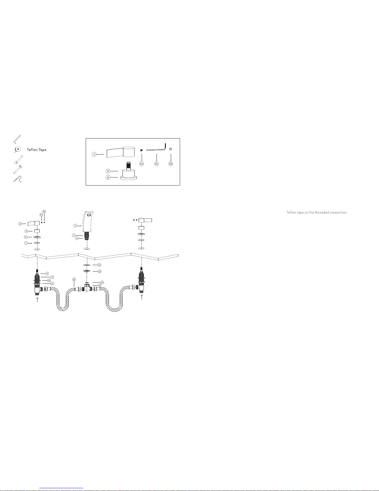
1. Shut off cold and hot water supply.
2. Place the rubber seal washer (#2) at the base of
the faucet body (#1) by sliding it over the spout
shank (#3).
3. Insert the spout shank (#3) through the hole of
the mounting deck from above.
4 . Place the faucet body (#1) in position.
5. From the underside of the mounting deck, with the
rubber mounting washer (#12) on the spout shank
(#3), screw and tighten the mounting nut (#13) by
using an adjustable wrench.
6. Screw and tighten the 3 way connector (#15) with
the rubber washer (#14) to the thread end of spout
shank (#3).
7. Since the handle (#4) was pre-installed at the
factory, it is necessary to remove the handle (#4)
from the valve stem (#8 ) by pulling out the
decorative cap (#4b) and using an Allen wrench
(#4c) to loosen the set screw (#4a), then remove
the ring (#5) and the escutcheon (#6 ) with the
rubber seal washer (#7).
8. Carefully insert the valve bodies (#9) in holes
next to the spout (#1) from the underside of the
mounting deck. Make sure the “HOT” tagged valve
body is on the left side and both valve outlets face
the spout (#1).
9. Adjust the rubber mounting washer (#10) and
the nut (#11 ) while screwing the escutcheon (#6 )
with the rubber seal washer (#7 ) onto the valve
body(#9 ). Tighten the mounting nut (#11 ) by using
an adjustable wrench.
10. Place the ring (#5 ) back to the valve (#9).
11. Attach the hot/red handle (#4) and the cold/blue
handle (#4) on the valve stem (#8), by tightening the
set screw (#4a) with an Allen wrench (#4c), then push
in the decorative cap (#4b).
12. Connect the stainless steel flexible hose (#16)
to the 3 way connector (#15) and the outlet of the
valve body (#9). Use Teflon tape.
13a. For 3/4” I.P. threaded connection: Connect the
hot water supply line to the inlet of the red tagged/
left valve body (#9), and connect the cold water
supply line to the inlet of the right valve body. Use
13b. For 1/2” CxC copper sweat connection:
Prior to soldering, remove the ceramic cartridge
with the stem (#8) from the valve body (#9) by using
a 21/32” socket wrench to loosen the hex nut. Avoid
soldering at excessively high temperature. Connect
the hot water supply to the inlet of the red tagged/
left valve body (#9), and connect the cold water
supply line to the inlet of the right valve body.
Installation Instructions
Care & Maintenance Instructions
Tools Required for Installation
Allen Wrench
Adjustable Wrench
Socket Wrench
Soldering Equipment
SSI products are de signed and engineered under
strict quality standa rds. Regular and proper
care of our products will ens ure years of trouble-
free service.
To clean, use a soft and damp cloth with warm soapy
water followed by rinsing with clean water and
drying with a soft cloth. Do not use abrasive or harsh
cleaners as they may result in finish damage.
Hot Water Inlet
Cold Water Inlet
 Loading...