

SSI Fluid F830, Fluid F820 Installation Instructions Manual
1. Shut off cold and hot water supplies.
6. Lead the end (#7) of spray hose (#5) through
spring (#8) and connection tube (#10). Place
spring (#8) onto small section of connection
tube (#10).
8. Pull spray head (#2) down so that spray hose
(#5) pulls through hook (#9). Release spray
head (#2) so the conical connector (#4) sits
inside the hook.
7. With seal washer (#11) inside connector (#12),
screw and tighten swivel nut (#7) at the end
of spray hose (#5) with the supplied metal
wrench (#6).
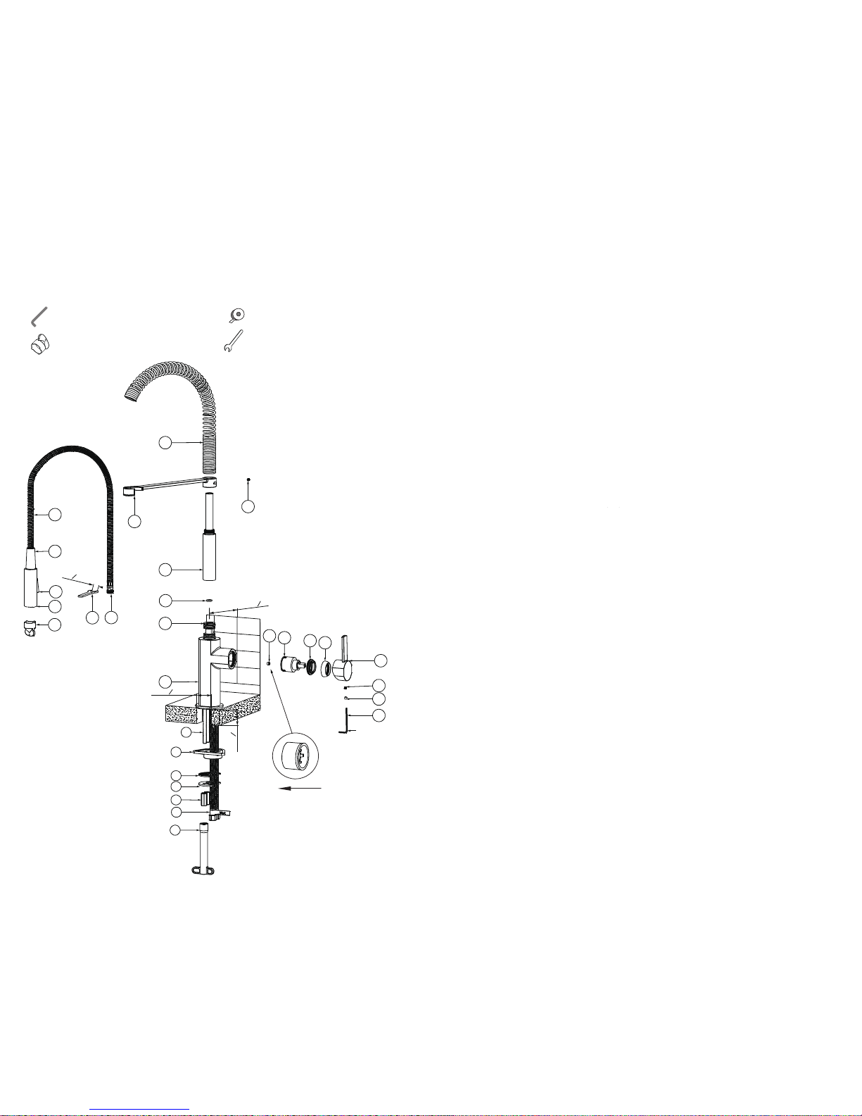
Installation InstructionsTools Required for Installation
Allen Wrench (supplied)
Aerator Service Key (supplied)
Wrench (supplied)
fluid products are designed and engineered under strict quality standards. Regular and proper
care of our products will ensure years of trouble-free service.
For Cartridge:
1. Shut off cold and hot water supplies.
3. Pull off handle (#24), unscrew cap (#25)
and remove retaining nut (#26) using an
adjustable wrench.
4. Pull off cartridge (#27) by hand.
5. Wash cartridge (#27) with clean running
water and ensure that any trapped debris
has been removed. Dry and lightly grease
all rubber seals (use only NSF approved
Silicone grease).
6. Replace cartridge (#27), retaining nut
(#26) and cap (#25) followed by handle (24).
Regularly remove with the supplied service
key(#1) and wash aerator of spray head (#2)
with clean running water and ensure any
trapped debris has been removed.
For Surface Finish:
Clean with a damp cloth and warm soapy water.
Then simply rinse off and wipe dry with a so
cloth. Do not use abrasive or harsh cleaners as
they may result in finish damage.
Note: If spacer (#15) is omied, mount-
-ing deck thickness can be increased by
5/8” (16mm) to a total of 2-1/8” (54mm).
Spray Paern: Turn on faucet and water
starts in stream paern from the aerator.
Push diverter buon (#3) to switch to spray.
2. On mounting surface the faucet hole
should be 1-1/2” (38 mm) in diameter.
The center of hole should be at least
3-1/16” (78mm) away from the back wall.
4. From below, fit spacer (#15), rubber
gasket (#16) and mounting plate (#17)
onto mounting rods (#14) and flex hoses
(#19). Screw mounting nuts (#18) onto
mounting rods (#14) and tighten with the
supplied tool (#20).
3. Place faucet body (#13) on the mounting
surface by feeding braided flex hoses
(#19) and mounting rods (#14) through
faucet hole.
5. Screw hook support (#9) onto connection
tube (#10) and tighten set screw (#23) with
the supplied Allen wrench (#21).
Max flow 1.5 gpm or 5.7 L/min
Flow pressure 15-72.5 psi at 60 psi
Max pressure 120 psi
Max temperature 176 F or 80 C
Max deck thickness 2-1/8”(54mm)
Inlet connection 3/8”comp
Specifications:
Teflon Tape
Care & Maintenance Instructions
2. Use Allen wrench (#21) to push silicon
plug (#22) into handle hub and loosen set
screw (#23) but do not remove it.
For Spray Aerator:
Remove cartridge (#27) and pull flow restrictor
(#28) out with needle-nose pliers. Rinse with
clean running water and ensure that any trapped
debris has been removed. Replace, paying careful
aention to the correct flow direction as shown.
If inserted incorrectly your faucet will not function
properly.
For Flow Restrictor:
™
For Spring:
The large spring (#8) on your faucet can change
shape if excessive force is used over time to
pull down the spray head. Avoid using excessive
force to pull spray head (#2) and hose (#5). If the
spring has changed shape, remove spray head
(#2) and hose (#5) and re-shape the spring (#8)
using two hands until the spring returns to its
original, uniform shape. Then, simply replace.
Flow Direction
13
27
26
25
2
9
4
8
28
5
10
12
3
7
23
MAX: 1
1
2
"
[38 mm]
3/32"(2.5mm)
Min: 3
1
16
"
[78 mm]
Back wall
I.D. 1
1
2
"
[38 mm]
6
9
16
"
[14 mm]
16
17
18
20
15
14
19
23
22
21
24
11
1
 Loading...