

SSI BINARY SOLVENT DELIVERY MODULE 90-2581 REV B, BINARY SOLVENT DELIVERY MODULE Operator's Manual
Page 1

P
Binary Solvent Delivery Module
Dual Series-III Pumps with Serial PC and Voltage Control
Operator's Manual
90-2581 rev B
Scientific Systems, Inc. 349 N. Science Park Road State College,
6803
Page 2

Page 3
yp
V
V
y
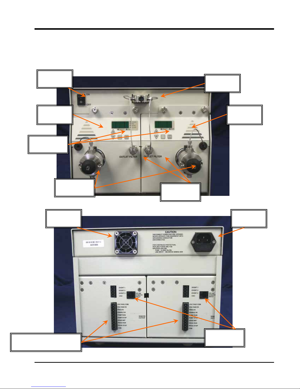
1. INTRODUCTION
This operator's manual contains information needed to install, operate, and
perform minor maintenance on the Binary Solvent Delivery Module. The
figures below are for reference of items described in the manual.
Power
Switch
“T” With
Outlet
Left
Drawer
Control
ads
Ke
Prime Purge
alves
Cooling
Fan
Outlet
Filters
Right
Drawer
Power
Entr
Auxiliary I/O
oltage Control, etc.
1-1
RS-232
Serial Ports
Page 4

1.1 Description of the Binary Solvent Delivery Module
The system consists of two Series III high performance metering
pumps, in a compact package with pulse dampener and an off-line
pressure transducer. The pumps use a drawer system for easy access to
internal components for troubleshooting & service. These features
allow for:
f Fast & easy setup:
Two inlet connection (from solvent reservoirs)
One outlet connection (to injector)
All connections accessible from front panel
f Modular:
Can be added to any system
f All Stainless steel or PEEK Fluid path, including pumps, valves
and fittings
f Modular pump bays for easy replacement and maintenance
f Self flushing pump heads for extended seal life and reduced
maintenance
f Pulse Dampener for reduced pulsation.
f Very high performance/price ratio
f Easily user adjustable process set points (flow rate, pressure. etc.)
via front key pads
f Digital readout of process parameters
f User settable upper/lower pressure and temperature limits
f RS-232 serial PC interface
f Compact size—Requires only 11 inches of bench space
The low pulsation flow produced by the reciprocating, singlepiston pump is achieved by using an advanced rapid-refill cam design,
programmed stepper motor acceleration, and an internal pulse damper.
1.1.1 Pump Features
They include:
• Rapid refill mechanism to reduce pulsation
• Stainless Steel or PEEK™ pumps head
1-2
• LED front panel readout of flow rate, pressure and upper/lower
pressure limits
• Flow adjustment in 0.001 ml increments, from 0.001 to 5.000
ml/min with a precision of 0.2% RSD (5mL/min heads)
Page 5
Flow adjustment in 0.01 ml increments, from 0.01 to 10.00
ml/min with a precision of 0.2% RSD (10mL/min heads)
• Microprocessor advanced control
• Digital stepper motor design to prevent flow rate drift
over time and temperature
• Back panel RS232 serial communications port for
complete control and status monitoring
• Remote analog inputs (e.g. voltage) to control flow rate
1.1.2 Wetted Pump Materials
Pump heads, check valve bodies, and tubing are made out Stainless
Steel or PEEK™. Other materials are synthetic ruby and sapphire
(check valve internals and piston).
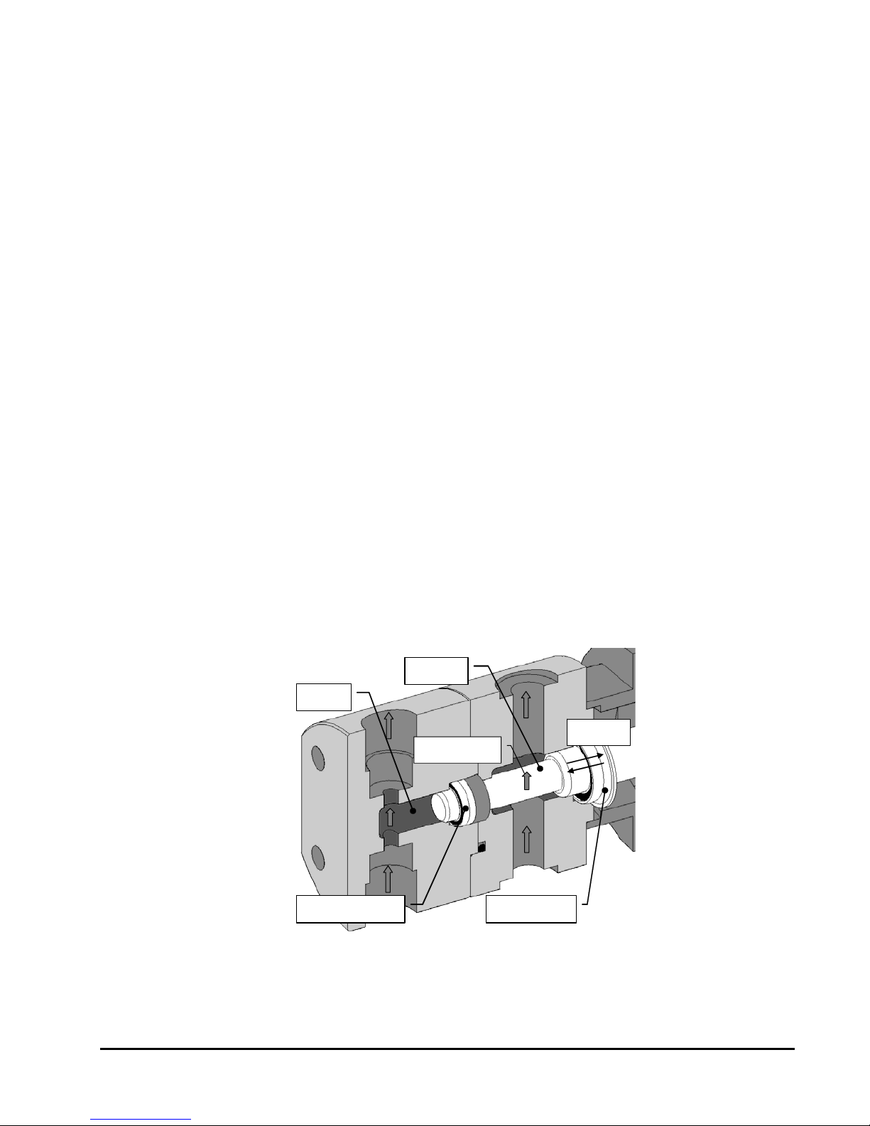
1.1.3 Self-Flushing Pump Head
Self-flushing pump heads provide continuous washing of the piston
surface without the inconvenience of a manual flush or gravity feed
arrangement. The self-flushing pump head uses a diaphragm and
secondary set of check valves to create a continuous and positive flow
in the area behind the high pressure pump seal. The flushing solution
washes away any buffer salts that have precipitated onto the piston.
If not removed, these precipitates can abrade the high pressure seal
and cause premature seal failure, leakage, and can possibly damage the
pump.
MOBILE
PHASE
SAPPHIRE
PISTON
1-3
FLOW OF
FLUSH SOLUTION
HIGH-PRESSURE SEAL
PRIMARY
SECONDARY
SELF-FLUSH SEAL
Figure 1-1. Self-Flushing Pump Head
PISTON
MOVEMENT
Page 6

1.1.4 Self-Flush and Seal Life
It is recommended that the Self Flush feature be used to improve
seal life in a number of applications. In particular, (as stated above) if
pumping Buffers, Acids/Bases or any inorganic solution near
saturation, the pump should utilize the Self Flush feature. With every
piston stroke, an extremely thin film of solution is pulled back past the
seal. If this zone is dry (without use of Self Flush), then crystals will
form with continuous operation, which will ultimately damage the
seal.
Another application where Self Flush is highly recommended is
when pumping Tetrahydrofuran (a.k.a. THR, Diethylene Oxide) or
other volatile solvents such as acetone (Note: THF and most solvents
are compatible only with all-Stainless Steel systems. THF will attack
PEEK). Volatile solvents will dry rapidly behind the seal (without the
use of Self Flush), which will dry and degrade the seal.
IPA, Methanol, 20% IPA/water mix or 20% Methanol/water mix
are good choices for the flush solution. Consult the factory for
specific recommendations.
1-4
Page 7

1.2 Specifications for the Binary Solvent Delivery Modules
Flow Rates ............0.000 to 5.000 mL/min for 5mL/min heads
0.00 to 10.00 mL/min for 10mL/min heads
Pressure ................ 0 to 6,000 p.s.i. for SS pump heads,
0 to 5,000 p.s.i. for PEEK™ heads,
Pressure Accuracy… .± 1% of full-scale pressure
Pressure Zero Offset. .± 2 p.s.i.
Flow Accuracy........± 2% for a flow rate of 0.20 mL/min and
above.
Flow Precision .......0.2% RSD
Dimensions ............9" high x 10.5" wide x 18.5" deep
Weight ...................34 lb
Power .................... 90-260 VAC, 50-60 Hz, 45W (The main
voltage supply shall not exceed ±10%)
Environmental……..Indoor use only
Altitude……………..2000 M
Temperature………10 to 30° C
Humidity……………20 to 90% Relative humidity
Remote Inputs . . . . RS-232, Voltage, Frequency
1-5
Page 8

2. INSTALLATION
2.1 Unpacking and Inspection
Prior to opening the shipping container, inspect it for damage or
evidence of mishandling. If it has been damaged or mishandled, notify
the carrier before opening the container. Once the container is opened,
inspect the contents for damage. Any damage should be reported to the
carrier immediately. Save the shipping container. Check the contents
against the packing list.
2.2 Location/Environment
The preferred environment for the Binary Solvent Delivery
Module is normal laboratory conditions. The area should be clean and
have a stable temperature and humidity. The specific temperature and
humidity conditions are 10 to 30 °C and 20% to 90% relative
humidity. The instrument should be located on a stable flat surface
with surrounding space for ventilation and the necessary electrical and
fluid connections.
2.3 Fluid Connections & Priming
There are only four connections to be made.
1. Connect left drawer pump solvent line supplied
2. Connect right drawer pump solvent line supplied
3. Connect line to injection valve from outlet “T”
4. Next, install the self flush. Connect the self flush inlet and
outlet (opaque) tubing as shown on the the next page.
Details on the proper installation of tubing and priming of the
pump and self flush is shown on the next page.
3-1
Page 9
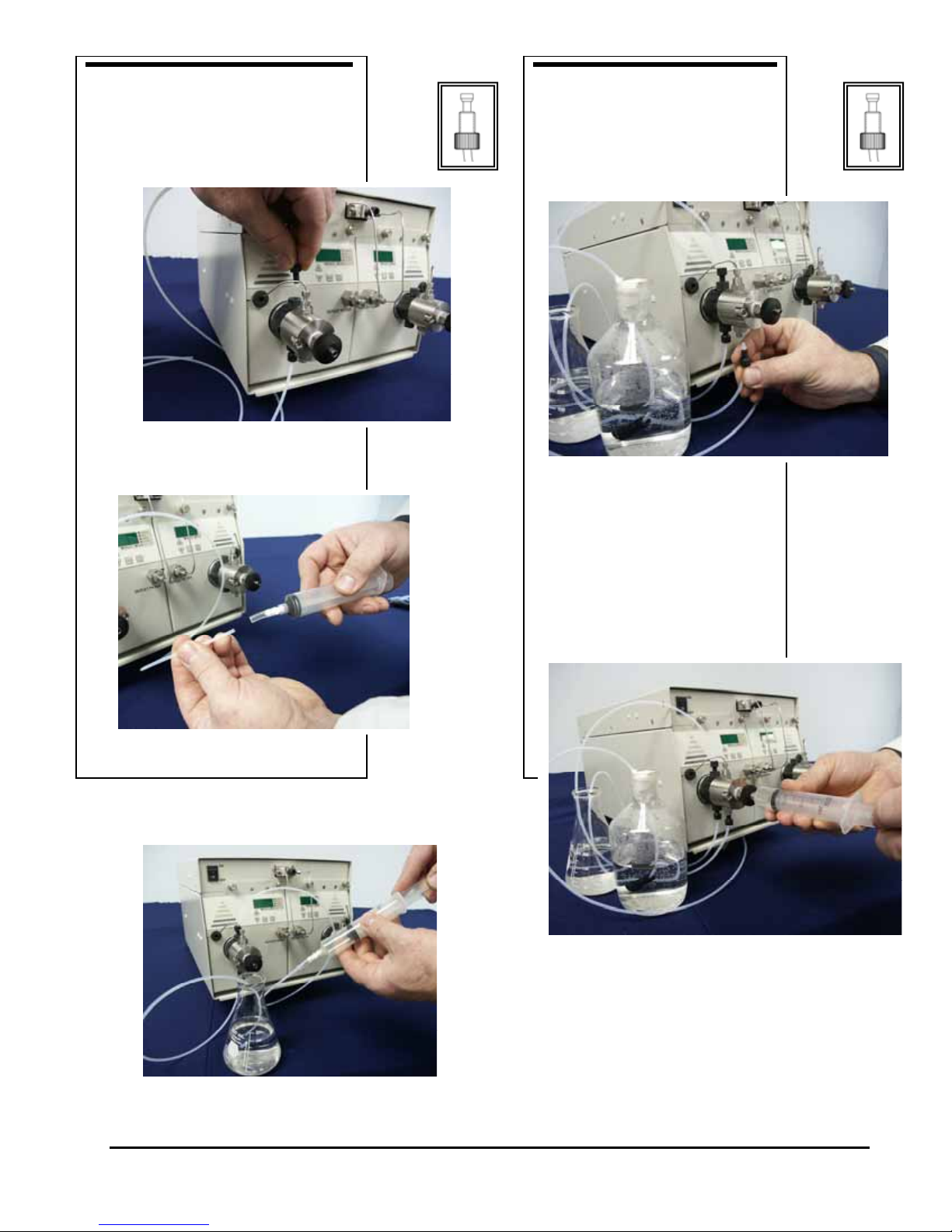
SELF-FLUSH
PUMP
Connect wash solution inlet and
outlet tubing
(opaque) to the flush housing as
shown.
Make sure ferrule is in the correct
position.
Screw syringe on luer fitting.
Insert wash outlet tubing end
into clear adapter.
Connect pump inlet tubing as
shown.
Make sure ferrule is in the
correct
position.
Ensure inlet line filter is
submersed into solvent.
Attach syringe to Prime-Purge
valve.
Open Prime-Purge valve by
turning knob counterclockwise
two turns.
Draw syringe back to prime.
Draw on syringe until no
3-2
Page 10

2.4 Electrical Connection
The system utilizes Universal Switching Power Supply, and will
accept voltages from 90 – 260 VAC, 50-60 Hz.
WARNING: Do not bypass the safety ground connection as
a serious shock hazard could result.
2.5 Solvent Preparation
Proper solvent preparation will prevent a great number of pumping
problems. The most common problem is bubble formation, which may
affect the flow rate consistency. Aside from leaky fittings, the problem
of bubble formation arises from two sources: solvent out-gassing and
cavitation. Filtration of HPLC solvents is also required.
2.5.1 Solvent Out-gassing and Sparging
Solvent out-gassing occurs because the mobile phase contains
dissolved atmospheric gases, primarily N2 and O2. These dissolved
gases may lead to bubble formation and should be removed by
degassing the mobile phase before or during use. The best practical
technique for degassing is to sparge the solvent with standard
laboratory grade (99.9+%) helium. Helium is only sparingly soluble
in HPLC solvents, so other gases dissolved in the solvent diffuse into
the helium bubbles and are swept from the system. Solvent filtration is
not an effective alternative to helium degassing.
It is recommended that you sparge the solvent vigorously for 10 to
15 minutes before using it. Then maintain a trickle sparge during use
to keep atmospheric gases from dissolving back into the mobile phase.
The sparged solvent must be continually blanketed with helium at 2 to
3 psi. Non- blanketed, sparged solvents will allow atmospheric gases
to dissolve back into the mobile phase within four hours.
Solvent mixtures using water and organic solvents (like methanol or
acetonitrile) hold less dissolved gas than pure solvents. Sparging to
reduce the amount of dissolved gas is therefore particularly important
when utilizing solvent mixture.
Even with sparging some out-gassing may be occur. A back
pressure regulator installed after the detector flow cell will help
prevent bubbles from forming and thus limit baseline noise.
WARNING: Always release pressure from the pump slowly. A rapid
pressure release could cause the pulse damper diaphragm to rupture.
3-3
Page 11

2.5.2 Cavitation
Cavitation occurs when inlet conditions restrict the flow of solvent
and vapor bubbles are formed during the inlet stroke. The key to
preventing cavitation is to reduce inlet restrictions. The most common
causes of inlet restrictions are crimped inlet lines and plugged inlet
filters. Inlet lines with tubing longer than 48" (120 cm) or with tubing
of less than 0.085" (2 mm) ID may also cause cavitation.
Placing the solvent reservoirs below the pump level also promotes
cavitation. The optimal location of the reservoirs is slightly above the
pump level, but it is adequate to have them on the same level as the
pump.
2.5.3 Filtration
Solvent filtration is good practice for the reliability of the Binary
Solvent Delivery Module and other components in a HPLC system.
Solvents should always be filtered with a 0.5 micron filter prior to use.
This ensures that no particles will interfere with the reliable operation of
the piston seals and check valves. Solvents in which buffers or other salts
readily precipitate out will need to be filtered more often. After filtration,
the solvents should be stored in a closed, particulate-free bottle.
2.5.4 Initial system pressurization (Daily)
IMPORTANT: To maximize accuracy at all pressures and flows
this pump contains a pulse damper for each solvent used. It is
important that the pump be brought to pressure with both pumps
running to insure that each pulse damper has the correct solvent in it.
It is recommended that the flow be set to the operational flow with an
equal mixture of the two solvents. Once the system has reached a
constant pressure the composition should be set to the initial
conditions.
2.6 Instrument Installation
2.6.1 Mobile Phase Reservoirs
The mobile phase reservoir should be placed at the same level or
slightly higher than the pump, never below the pump, and the inlet
tubing should be as short as practical. These steps minimize pressure
losses on the inlet side of the pump during refill and help to avoid
bubble formation. These steps are particularly important when using
high vapor pressure solvents (hexane, methylene chloride, etc.).
Mobile phases should be degassed, filtered and covered. (See Section
2.4.)
3-4
Page 12

2.6.2 Self-Flush Solution
Self-flush heads require 250-500 mL of flushing solution. See
section 1.1.4 for self-flush solution recommendations. A pH indicator
that will indicate the concentration of salts in the solution is
recommended as a reminder to change the solution. This flush solution
should be replaced with a fresh solution weekly to avoid frequent
pump maintenance.
2.6.3 Inlet Tubing and Filters
The table below shows the inlet tubing and filter used in the Binary
Solvent Delivery Module. All inlet lines are supplied in a 30" (76 cm)
length and are made of a fluoropolymer material.
2.6.4 Priming the Pump and the Flushing Lines
Connect a syringe to the outlet tubing. Run the pump at a flowrate
of 3 to 5 ml/min. Prime the pump by pulling mobile phase and any air
bubbles through the system and into the syringe (a minimum of 20
ml).
To prime the flush lines for a self-flush head, simply place the inlet
line in the flush solution and connect a syringe to the outlet line and
apply suction until the line is filled with flush solution. Place the
outlet line in the flush solution. Secure both flush lines in the flush
solution container so they stay immersed during pump operation.
2.6.6 Long Term Pressure Calibration Accuracy
This note applies if your pump is equipped with an electronic
pressure transducer. The transducer has been zeroed and calibrated at
the factory. Over the life of the pump, some drift may occur. For
example, it is typical for the zero to drift < 10 p.s.i. after about 1 year
of operation (i.e., with no back pressure on the pump a reading of 1-9
p.s.i. may be displayed). A similar drift may also occur at higher
pressures, and are typically less than 1% (e.g. <50 p.s.i. at 6,000 p.s.i.
back pressure).
If pressure calibration and/or drift is a concern, consult the factory.
The pump can be shipped back to SSI for recalibration. Alternatively,
written calibration and zero-reset procedures are available. Consult the
factory to receive these instructions.
3-5
Page 13

2.7 Preparation for Storage or Shipping
2.7.1 Isopropanol Flush
Disconnect the outlet tubing from the pump. Place the inlet filter in
isopropanol. Use a syringe to draw a minimum of 50 ml through the
pump. Pump a minimum of 5 ml of isopropanol to exit. Leave the inlet
tubing connected to the pump. Place the inlet filter in a small plastic
bag and attach it to the tubing with a rubber band. Plug the outlet port
with the shipping plug or leave a length of outlet tubing on the pump
or cover the outlet port with plastic film.
2.7.2 Packaging for Shipping
CAUTION: Reship in the original carton, if possible. If the original carton is
not available, wrap the pump in several layers of bubble wrap and cushion the
bottom, top, and all four sides with 2" of packaging foam. Although heavy, an
HPLC pump is a delicate instrument and must be carefully packaged to
withstand the shocks and vibration of shipment.
3-6
Page 14
3. OPERATION
3.1 Pump Front Panel Controls and Indicators
3.1.1 Control Panel
3.1.1.1 Digital Display
The 3-digit display shows the pump flow rate (mL/min), system
pressure (psi), or the set upper or lower pressure limit (psi) when
operating. Choice of display is selected with the MODE key.
3.1.1.2 Digital Display Pump Keypad
∆
∇
MODE
RUN
STOP
Fast And Slow Button Repeat On The Up And Down Arrow Buttons:
If the UP-ARROW or DOWN-ARROW button is held down for more
than approximately one half of a second, the button press will repeat at
a slow rate of approximately 10 times a second. Once slow button
repeat has begun, fast button repeat can be initiated by using a second
finger to press down the second arrow button. During fast button
repeat, the button press will repeat at a rate of approximately 100
times a second. Switching back and forth between repeat speeds can
be accomplished by pressing and releasing the second arrow button
while keeping the first arrow button held down.
When pressed, this button increases the flow rate.
When pressed, this button decreases the flow rate.
Use this button to cycle through the four display modes: flow rate,
pressure, upper pressure limit, or lower pressure limit. A status LED
to the right of the digital display indicates which mode is active.
When pressed, this button alternately starts and stops the pump.
3-7
Page 15

3.1.1.3 Status LEDs
Q ml/min
Q PSI
Q HI PR
Q LO PR
Q RUN
Q FAULT
When lit, the digital display shows flow rate in mL/min.
When lit, the digital display shows system pressure in psi.
When lit, the display shows the user-set upper pressure limit in psi.
When lit, the display shows the user-set lower pressure limit in psi.
Lights to indicate that the pump is running.
Lights when a fault occurs and stops the pump.
3.1.1.2 Power-up Configuration
Non-volatile Memory Reset: If the pump is operating erratically,
there is the possibility that the memory has been corrupted. To reset
the memory and restore the pump to it's default parameters, press and
hold the UP-ARROW button when the power is switched on. Release
the button when the display reads "rES". The parameters stored in
non-volatile memory, i.e., the flowrate, the pressure compensation, the
voltage/frequency select, the lower pressure limit, and the upper
pressure limit will be set to the factory default values. The head type
setting is the only parameter not changed by the non-volatile memory
reset function. If the firmware is upgraded to a newer version, a nonvolatile memory reset will automatically occur the first time the power
is switched on.
3.1.1.5 Power-Up Tests
Display Software Version Mode: The software version can be
displayed during power-up by pressing and holding the RUN/STOP
and the UP-ARROW buttons when the power is switched on. Release
the buttons when the display reads "UEr". The decimal point number
displayed on the display is the software version. To exit this mode,
press the RUN/STOP button.
3-8
Page 16

Align Refill Switch Mode: The signal that initiates the refill phase
can be displayed during power-up by pressing and holding the PRIME
and the UP-ARROW buttons when the power is switched on. Release
the buttons when the display displays "rFL". When the slotted disk
allows the light beam to pass from the emitter to the detector on the
slotted optical switch a pulse will be generated which signals the
beginning of refill. When this pulse occurs the three horizontal
segments displayed at the top of the display will turn off and the three
horizontal segments at the bottom of the display will turn on. To exit
this mode, press the RUN/STOP button.
Serial Port Loopback Test Mode: If an external device will not
communicate to the pump via the serial port, the serial port loopback
test can be used to verify that the serial port is functioning properly.
During power-up press and hold the UP-ARROW and the DOWNARROW buttons when the power is switched on and then release the
buttons. The display must display "C00" for the first half of the test to
pass. Plug in the serial port loop back plug (A modular plug with pins
2 & 5 jumpered together and pins 3 & 4 jumpered together.). The
display must read "C11" for the second half of the test to pass. To exit
this mode, press the RUN/STOP button.
3.5 Rear Panel Remote Input
An RS-232 modular jacks are provided on the back panel. A
computer, with appropriate software, can be used as a remote
controlling device for pump operation via this connection.
See Appendix A for details on connection and operation.
3.6 Symbols
The following symbols may appear on back panel of the unit:
Caution: To avoid chemical or electrical hazards, always observe safe
laboratory practices while operating this equipment.
Caution: To avoid electrical shock and possible injury, remove the power
cord from the back panel of this equipment before performing any
type of service procedures.
Note: The user shall be made aware that, if equipment is used in a
manner not specified by the manufacturer, the protection provided by
the equipment may be impaired.
3-9
Page 17

4. THEORY OF OPERATION
4.1 Pump Mechanical Operation
4.1.1 Liquid System Flow Path
The flow path of the Binary Solvent Delivery Module starts at the
inlet reservoir filter passes through the inlet check valve, then through
the pump head, and finally exits through the outlet check valve.
4.1.2 Pump Cycle
The pump cycle consists of two phases, the pumping phase, when
fluid is metered out of the pump at high pressure, and the refill phase,
when fluid is rapidly drawn into the pump.
During the pumping phase, the pump piston moves forward at a
programmed speed; this results in a stable flow from the pump. The piston
is driven by a linear rapid refill cam which is belt driven by the motor.
At the end of the pumping phase, the pump enters the refill phase.
The piston quickly retracts, refilling the pump head with solvent, and
the piston begins to move forward again as the pumping phase begins.
The motor speed is increased during refill to reduce refill time and
to pre-compress the solvent at the beginning of the pumping phase.
Since the output flow completely stops during refill, an optional,
external pulse damper is necessary for applications requiring
extremely low pulsation levels.
For optimal operation of the check valves, a back-pressure of at least
25 psi is required. Operating at lower pressures can lead to improper
seating of the valves and subsequently inaccurate flow rates.
4.1.3 Pulse Damping
The diaphragm-type pulse damper (inside the pump drawer)
consists of a compressible fluid (isopropanol) held in an isolated
cavity by an inert but flexible diaphragm. During the pumping phase
of the pump cycle, the fluid pressure of the mobile phase displaces the
diaphragm, compressing the fluid in the cavity and storing energy.
During the pump refill phase the pressure on the diaphragm is reduced
and the compressed fluid expands, releasing the energy it has stored.
This helps to stabilize flow rate and pressure. The amount of mobile
phase in contact with the pulse damper is small, only 0.25 mL at 2,500
psi, and the geometry used insures that the flow path is completely
swept, so solvent “memory effects” are virtually eliminated.
To be effective, the pulse damper requires a backpressure of
approximately 500 psi or greater.
4-1
Page 18

4.2 Electronic Control
4.2.1 Microprocessor Control
(1) provides control signals to the motor drive circuitry, (2) interfaces
with the keyboard/display, (3) receives signals from the refill flag, and
(4) provides external input/output (RS-232) interfacing. Firmware
programming is stored in an EPROM.
The remaining revolution of the cam provides piston displacement for
outward flow of the mobile phase. In addition to the rapid refill
characteristics of the drive, the onset of refill is detected by an infrared
optical sensor. The microprocessor changes the refill speed of the
motor to an optimum for the set flow rate. At 1ml/min, the refill rate is
more than five times faster than if the motor operated at constant
speed. The optimum refill rate minimizes the resulting pulsation while
avoiding cavitation in the pump head.
the operating pressure and the compressibility of the fluid being
pumped. The Binary Solvent Delivery Module is calibrated at 1000 psi
using an 80:20 mixture of water and isopropanol.
The pump is controlled by hybrid microprocessor circuitry which
An eccentric cam provides refill in a fraction of the full cam cycle.
The flow rate of any high pressure pump can vary depending on
4.2.2 DC Power Supply
Power for the pump is provided by a switching power supply
which accepts voltages from 90 – 240 VAC. Output is 24 VDC for the
pumps and heater. A switching 5 VDC supply is also provided to
power control and display circuits.
4.2.3 Remote Interfacing
RS-232C modular jacks are provided on the back panel. See
Appendix A for information on operation via this connection.
4.2.4 Motor Stall Detector
The motor can stall and create a loud buzzing sound if the flow
path connected to the pump's outlet becomes plugged, if the pressure
exceeds the maximum pressure rating of the pump, or if the
mechanism jams. If a motor stall occurs, the electrical current being
supplied to the motor is turned off and the fault light is turned on.
The Motor Stall Detector is enabled or disabled during power-up by
pressing and holding the RUN/STOP and the PRIME buttons while
the power is switched on. Release the buttons when the display
displays "SFE". To enable the Motor Stall Detector press the UPARROW button and the display will display "On". To disable the
4-2
Page 19

Motor Stall Detector press the DOWN-ARROW button and the
display will display "OFF". To exit this mode and store the current
setting in non-volatile memory, press the RUN/STOP button.
The Motor Stall Detector uses a timer to determine if the camshaft has
stopped turning or if the refill switch is defective. The timer begins
timing after the pump accelerates or decelerates to its set point flow rate.
If the Motor Stall Detector has been enabled, and the camshaft stops
turning or the refill switch stops operating, the fault will be detected
between the time it takes to complete 1 to 2 pump cycles. One
revolution of the camshaft produces a delivery phase and a refill phase.
The fault is canceled by using one of the following methods: (1) by
pressing the RUN/STOP button on the front panel, (2) by sending a
stop command "ST" via the serial communications port on the back
panel, or (3) by connecting the PUMP-STOP input to COM on the
back panel, or removing the connection between the PUMP-RUN
input and COM if the PUMP-STOP input is permanently jumpered to
COM on the back panel. Note: the PUMP-RUN, PUMP-STOP, and
COM are an option and do not exist on the standard pump.
4-3
Page 20
5. MAINTENANCE
Cleaning and minor repairs of the Binary pump can be performed
as outlined below.
NOTE: Lower than normal pressure, pressure variations, or
leaks in the pumping system can all indicate possible
problems with the piston seal, piston, or check valves.
Piston seal replacement could be necessary after 1,000
hours of running time. See Section 5.2.3.
5.1 Filter Replacement
5.1.1 Inlet Filters
Inlet filters should be checked periodically to ensure that they are
clean and not restricting flow. A restriction could cause cavitation and
flow loss in the pump. Two problems that can plug an inlet filter are
microbial growth and impure solvents. To prevent microbial growth,
use at least 10-20% organic solvent in the mobile phase or add a
growth-inhibiting compound. If you pump 100% water or an aqueous
solution without any inhibitors, microbes will grow in the inlet filter
over time, even if you make fresh solution every day. Always use well
filtered, HPLC grade solvents for your mobile phase.
5.2 Changing Pump Heads
5.2.1 Removing a Pump Head
CAUTION: The sapphire piston is fragile. Twisting the
pump head during removal can cause the piston to break.
Closely follow instructions during head removal and
replacement to avoid breakage.
As a guide to pump head assembly, the standard pump heads are
shown in Figures 5-1 through 5-4. All of the Binary pump heads have
a similar arrangement.
1. Turn OFF the power to the Binary pump.
2. Remove the inlet line and filter from the mobile phase reservoir. Be
careful not to damage the inlet filter or crimp the Teflon™ tubing.
7-1
Page 21

CAUTION: Check that the Allen nuts at the front of the
pump head are secure before removing any tubing from the
pump head.
3. Remove the inlet line from the inlet check valve.
4. Remove the outlet line from the outlet check valve.
5. Remove inlet and outlet self-flush check valves.
6. Momentarily turn ON the Binary pump and quickly turn OFF the
power upon hearing the refill stroke. This reduces the extension of the
piston and decreases the possibility of piston breakage.
7. Unplug the power cord.
8. Carefully remove the two Allen nuts at the front of the pump head.
CAUTION: Use care when removing the pump head.
Twisting the pump head can cause the piston to break.
9. Carefully separate the pump head from the pump. Move the pump
head straight out from the pump and remove it from the piston. Be
careful not to break or damage the piston. Also remove the seal and
seal backup washer from the piston if they did not stay in the pump
head.
10. Carefully separate the flush housing from the pump. Move the flush
housing straight out from the pump and remove it from the piston. Be
careful not to break or damage the piston. Also remove the self-flush
seal from the piston if it did not stay in the flush housing.
7-2
Page 22

OUTLET FLUSHING CHECK VALVE
OUTLET CHECK VALVE
PUMP HEAD
O-RING
SEAL BACKUP PLATE
SELF-FLUSH SEAL
SELF-FLUSH HOUSING
INLET FLUSHING CHECK VALVE
SEAL BACKUP WASHER
SEAL
INLET CHECK VALVE
Figure 5-1. Stainless Steel Self-Flushing Pump Head Assembly
PISTON
HOLE PLUG
OUTLET CHECK VALVE
PUMP HEAD
O-RING
SEAL BACKUP WASHER
SEAL
INLET CHECK VALVE
NON-FLUSH GUIDE BUSHING
SELF-FLUSH HOUS I NG
PISTON
SEAL BACKUP PLATE
Figure 5-2. Stainless Steel Non-Self-Flushing Pump Head Assembly
7-3
Page 23

OUTLET FLUSHING
CHECK VALVE
OUTLET CHECK VALVE
PUMP HEAD
O-RING
PISTON
SEAL BACKUP PLATE
SELF-FLUSH SEAL
SELF FLUSH HOUSING
INLET FLUSHING CHECK VALVE
SEAL BACKUP WASHER
SEAL
INLET CHECK VALVE
Figure 5-3. Bioclean (PEEK™) Self-Flushing Pump Head Assembly
HOLE PLUG
OUTLET CHECK VALVE
NON-FLUSH GUIDE BUSHING
PUMP HEAD
SELF-FLUSH HOUSING
O-RING
SEAL BACKUP WASHER
SEAL
INLET CHECK VALVE
PISTON
SEAL BACKUP PLATE
Figure 5-4. Bioclean (PEEK™) Non-Self-Flushing Pump Head Assembly
7-4
Page 24

5.2.2 Cleaning the Pump Head Assembly
NOTE: If you choose to remove the piston seal or self-flush
seals, you should have a new set on hand to install after
cleaning. It is not recommended that you reinstall used
piston or self-flush seals since they are likely to be
scratched and damaged during removal and would not
provide a reliable seal if reused. If you decide to remove the
seals, use only the flanged end of the plastic seal removal
tool supplied with the seal replacement kit and avoid
scratching the sealing surface in the pump head. See
Section 5.2.3 for seal replacement instructions.
1. Inspect the piston seal cavity in the pump head. Remove any foreign
material using a cotton swab, or equivalent, and avoid scratching the
sealing surfaces. Repeat for the self-flush housing. Be sure no fibers
from the cleaning swab remain in the components.
2. The pump head, check valves, and self-flush housing may be further
cleaned using a laboratory grade detergent solution in an ultrasonic
bath for at least 30 minutes, followed by rinsing for at least 10 minutes
in distilled water. Be sure that all particles loosened by the above
procedures have been removed from the components before reassembly.
CAUTION: When cleaning check valves, be sure that the
ball is not against the seat in the ultrasonic bath. This may
destroy the precision matched sealing surface and the valve
will not check.
CAUTION: If removing the check valves, keep them in the
orientation shown below the entire time they are not
installed in the pump head. The assemblies may fall apart,
parts may be lost, and they may not operate properly when
re-assembled.
7-5
Page 25

3. If the check valves have been removed, tighten the check valves on
stainless steel pumps to 75 inch-pounds or enough to seal at maximum
pressure. Do not exceed maximum torque. For Bioclean (PEEK™)
pumps, tighten each check valve firmly by hand. Do not go ¼ turn past
finger tight.
NOTE: The inlet check valve has a larger opening (1/4"-28,
flat-bottom seat) for the 1/8" inlet tubing; the outlet check
valve has a smaller opening (#10-32, cone seat) for the
1/16" outlet tubing. The inlet check valve must be connected
at the larger opening in the pump head. See Figure 5-5.
If the piston and flushing seals have been removed, insert new
seals as described in Section 5.2.3, then continue with Section 5.2.5 to
replace the pump head.
7-6
Page 26

SINGLE
INLET HOLE
W
O
L
F
INLET CHECK VALVE (SS)
MULTIPLE
OUTLET HOLES
W
O
L
F
OUTLET CHECK VALVE (SS)
RING
W
O
L
F
INLET CHECK VALVE (PEEK)
W
O
L
F
RING
OUTLET CH ECK VALVE (PEEK)
TRANSPARENT
WASHER
OUTLET
W
O
L
F
SELF-FLUSH
CHEC K VALVE
CROSS BALL
RETAINER
W
O
L
F
SELF-FLUSH
CHECK VAL VE
Figure 5-5. Check Valves
5.2.3 Replacing Piston Seals
Lower than normal pressure, pressure variations, and leaks in the
pumping system can all indicate possible problems with the piston
seal. Depending on the fluid or mobile phase used, piston seal
replacement is often necessary after 1000 hours of running time.
Each replacement seal kit contains one seal, one backup washer,
one self-flush seal, one non-flush guide bushing, two seal
insertion/removal tools, and a pad to clean the piston when changing
the seal.
INLET
7-7
Page 27

5.2.3.1 Removing the Seals
1. Remove the pump head as described in Section 5.2.1. Use caution so
as not to damage the sapphire piston.
2. Insert the flanged end of the seal insertion/removal tool into the seal
cavity on the pump head. Tilt it slightly so that flange is under the seal
and pull out the seal.
CAUTION: Using any other “tool” will scratch the finish.
3. Repeat the procedure for the low-pressure seal in the flush housing.
4. Inspect, and if necessary, clean the pump head as described in Section
5.2.2.
5.2.3.2 Cleaning the Piston
1. Once the pump head and self-flush housing are removed, gently
remove the seal back-up plate by using either a toothpick or small
screwdriver in the slot on top of the pump housing.
2. Grasp the metal base of the piston assembly so that you avoid exerting
any side load on the sapphire rod, and remove the piston from the slot
in the carrier by sliding it up.
3. Use the scouring pad included in the seal replacement kit to clean the
piston. Gently squeeze the piston within a folded section of the pad
and rub the pad along the length of the piston. Rotate the piston
frequently to assure the entire surface is scrubbed. Do not exert
pressure perpendicular to the length of the piston, as this may cause
the piston to break. After scouring, use a lint-free cloth, dampened
with alcohol, to wipe the piston clean.
4. Grasp the metal base of the piston assembly, and insert it into the slot
in the piston carrier until it bottoms in the slot.
5.2.3.3 Replacing the Seals
1. Place a high-pressure replacement seal on the rod-shaped end of the
seal insertion/removal tool so that the spring is visible when the seal is
fully seated on the tool. Insert the tool into the pump head so that the
open side of the seal enters first, facing the high pressure cavity of the
pump head. Be careful to line up the seal with the cavity while
inserting. Then withdraw the tool, leaving the seal in the pump head.
When you look into the pump head cavity, only the polymer portion of
the seal should be visible.
7-8
Page 28

2. Place a self-flush replacement seal on the seal insertion/removal tool
so that the spring in the seal is visible when the seal is on the tool. As
in the previous step, insert the tool and seal into the seal cavity on the
flushing housing, taking care to line up the seal with the cavity, and
then withdraw the tool. When the seal is fully inserted only the
polymer part of the seal will be visible in the seal cavity.
3. Place seal back-up washer over the high-pressure seal. Place seal
back-up plate back into pump housing if it was removed. Orientation
is not important in these cases.
4. Attach the pump head as described in Section 5.2.5. Use caution so as
not to damage the sapphire piston.
5. Condition the new seal as described in Section 5.3.
5.2.4 Changing the Piston
1. Remove the pump head as described in Section 5.2.1. Use caution so
as not to damage the sapphire piston.
2. Grasp the metal base of the piston assembly so that you avoid exerting
any side load on the sapphire rod, and remove the piston from the slot
in the carrier by sliding it up.
3. Grasp the metal base of the replacement piston assembly, and insert it
into the slot in the piston carrier until it bottoms in the slot.
4. Attach the pump head as described in Section 5.2.5. Use caution so as
not to damage the sapphire piston.
7-9
Page 29

5.2.5 Replacing the Pump Head
CAUTION: The sapphire piston is fragile. Twisting the
pump head during replacement can cause the piston to
break. Closely follow instructions during head removal and
replacement to avoid breakage.
1. Make sure that the inlet valve is on the bottom and the outlet valve is
on the top. Carefully align the self-flush housing and gently slide it
into place on the pump. If misalignment with the piston occurs, gently
push up on the piston holder.
2. Line up the pump head and carefully slide it into place. Be sure that
the inlet valve is on the bottom and the outlet valve is on the top. Do
not force the pump head into place.
3. Finger tighten both knurled nuts into place. To tighten firmly,
alternately turn nuts 1/4 turn while gently wiggling the pump head to
center it.
CAUTION: Use care when replacing the pump head.
Twisting the pump head can cause the piston to break.
4. Re-attach the inlet and outlet lines. Reconnect the self-flush lines and
fittings to the self-flush check valves. Change the flushing solution.
5.3 Conditioning New Seals
NOTE: Use only organic solvents to break-in new seals.
Buffer solutions and salt solutions should never be used to
break-in new seals.
Using a restrictor coil or a suitable column, run the pump with a
50:50 solution of isopropanol (or methanol) and water for 30 minutes
at the back pressure and flow rate listed under PHASE 1 below and
according to the pump head type. Then run the pump for 15 minutes at
a back pressure and flow rate listed under PHASE 2 below.
PHASE 1 (30 min.) PHASE 2 (15 min.)
Pump Head Type Pressure Flow Rate Pressure Flow Rate
10 mL
(SS or PEEK)
5 mL
(SS or PEEK)
7-10
1000 psi < 3 mL/min. 3000-4000 psi 3-4 mL/min.
1000 psi < 2.5 mL/min. 1500 psi < 5 mL/min.
Page 30
5.4 Check Valve Cleaning and Replacement
Many check valve problems are the result of small particles
interfering with the operation of the check valve. As a result, most
problems can be solved by pumping a strong solution of liquid,
laboratory grade detergent through the check valves at a rate of
1 mL/min for one hour. After washing with detergent, pump distilled
water through the pump for fifteen minutes. Always direct the output
directly to a waste beaker during cleaning. If this does not work, the
check valve should be replaced.
CAUTION: When removing the check valves, keep them in
the orientation shown below the entire time they are not
installed in the pump head. The assemblies may fall apart,
parts may be lost, and they may not operate properly when
re-assembled.
5.5 Pulse Damper Replacement
5.5.1 Removing the Pulse Damper
WARNING: There are potentially lethal voltages inside the
pump case. Disconnect the line cord before removing the
cover. Never bypass the power grounds.
1. Make certain that the system has been depressurized. Unplug the power
cord and remove the cover.
2. Disconnect the tubing from the pulse damper.
3. Disconnect the transducer from the circuit board.
4. Remove the four screws that secure the pulse damper from the underside
of the pump.
5. Remove the pulse damper.
7-11
5.5.2 Pulse Damper Refurbishing
Refurbishing the pulse damper is a time-consuming
procedure. You may want to return the pulse damper to have it
Page 31

rebuilt. Do not attempt to refill or refurbish the pulse damper
until you have a refurbishing kit. Instructions are furnished with
the kit.
5.5.3 Pulse Damper Installation
1. Position the pulse damper, aligning it with the four mounting holes in the
bottom of the cabinet. The pressure transducer should be pointed toward the
rear of the cabinet.
2. From the underside of the pump cabinet, tighten the four screws to hold the
pulse damper in place.
3. Connect the tubing from the pump head to the port at the rear of the pulse
damper (i.e., toward the rear of the cabinet). Connect the line from the
prime/purge valve to the other port, toward the front panel.
4. Connect the transducer’s wire harness connector to pressure board
connector P3.
5. Replace the cover on the pump.
5.6 Cleaning the Pump
1. Disconnect the column inlet tube from the column.
2. Direct the column inlet tube (the tube from the injector outlet) to a
3. Set the flow rate to maximum.
4. Turn the injector to the INJECT position.
5. Pump 100% methanol or isopropanol through the pump and injector
6. Pump 100% filtered, distilled water through the pump and injector for
For stainless steel flow paths, proceed to Step 7; For PEEK ™ flow
7. Pump a 20% nitric acid/water solution through the pump and injector
8. Flush the pump and injector with 100% filtered, distilled water for at
9. Pump 100% isopropanol through the pump and injector for 3 minutes.
The pump is now prepared for any mobile phase or short- or long-term
waste beaker.
for 3 minutes.
3 minutes.
paths, skip to step 10.
WARNING: Use standard laboratory procedures and
extreme care when handling strong acids and bases.
for 3 minutes.
least 3 minutes.
shutdown.
7-12
Page 32

10. If storing the pump for more than 12 hours fill each pump head with
100% isopropanol then seal the inlets and outlet with the supplied
plugs.
5.7 Lubrication
The Binary pump has modest lubrication requirements. The
bearings in the pump housing and piston carrier are permanently
lubricated and require no maintenance. A small dab of light grease
such as Lubriplate 630-AA on the cam is the only recommended
lubrication. Be sure not to get lubricant on the body of the piston
carrier, as this can retard its movement and interfere with proper
pumping.
NOTE: Keeping the interior of the pump free of dirt and dust
will extend the pump’s useful life.
5.8 Other Pump Maintenance
removing the pump drawer. To do so, turn off power at front switch.
Unplug power cord. Ensure there is no power to the system.
Disconnect the inlet line and disconnect pump outlet at the “T”
Connector Block above. Unscrew the two thumbscrews on the upper
portion of the drawer until fully released (counterclockwise). Pull the
drawer out as shown on next page.
The internal components of the pump can be accessed by
Note: Drawer can be removed completely.
7-13
Page 33

The Pump mechanism, Control Boards, & Pulse Dampener (with Pressure
Transducer) are accessible by removing pump drawer.
7-14
Page 34
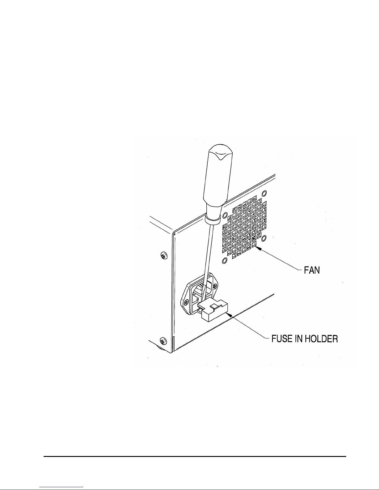
5.9 Fuse Replacement
the fuses are located in the power entry module at the rear of the
cabinet and are in series with the AC input line. The other fuse is
located on the circuit board and is in series with the 24 VDC supply.
plugged in and the on/off power entry switch is on and the display
does not light, check the two fuses in the power entry module. To gain
access to these fuses, gently pry off the cover plate with a small flatbladed screwdriver. Replace with fuses of the correct rating: 2 A slowblo for 120 VAC systems.
Three fuses protect the Binary Solvent Delivery Module. Two of
Troubleshooting the fuses is straightforward. If the power cord is
7-15
Page 35

5.10 Battery Replacement (If applicable) See attached photo for battery option.
Depending on the version of drive board assembly installed, the board may not have a
battery. If the printed circuit board does not have a battery, it is designed with circuitry that
does not require a battery backup and you should disregard the following instructions.
The battery provides power for the memory that holds the current
pump configuration. If the pump is set at a flowrate and the power is
turned off, when the power is turned back on the flowrate should
appear as it was set. If this flowrate does not appear the battery will
need replaced.
CAUTION: Be sure to disconnect power cord before removing
cover to insure there is no voltage present.
CAUTION: Circuit boards can be damaged by Electro Static
Discharge (ESD). Follow standard ESD procedures when
handling circuit boards.
1. Unplug the unit.
2. Remove the cover.
3. Turn the unit so that the pump heads are to the right. The battery can
be seen in the lower right corner of the circuit board. The battery is
circular and has a positive pole mark (+) on the top. Gently pull it
from its socket.
4. With the positive mark (+) up, gently slide the new battery into the
battery socket. Be sure the battery is all the way into place. It must
contact the base of the battery socket.
5. Replace the cover to the unit.
6. Plug the unit back in.
PCA with Battery PCA without Battery
7-16
Page 36

6. PROBLEM SOLVING
Quick Guide to Problem Solving
You Notice
1. Uneven pressure
trace.
2. Pressure drops.
3. No flow out the
outlet check valve.
1. Uneven pressure
trace.
2. Pressure drops.
3. Fluid between the
pump head and the
retainer.
Pump makes a loud
clanging or slapping
noise (intermittent
contact with cam).
No power when pump
turned ON.
Blue dye in mobile
phase.
Pump runs for 50
pump strokes, then
shuts down.
1. Pump shuts down
after run is called
even with no
column connected.
2. Pump runs to
maximum pressure
and shuts down.
No power when pump
turned ON. Fan does
not run.
Front panel appears
OK but pump motor
does not run.
PEEK fittings or
components leak.
This May Mean
1. Bubble in
check valve.
2. Leaks in
system.
3. Dirty check
valve.
4. Bad check
valve.
1. Leaks in
system.
2. The piston
seal or
diaphragm is
worn.
Piston carrier is
catching in
piston guide.
Blown fuses in
the power entry
module.
Pulse damper
diaphragm has
burst.
Lower pressure
limit is
activating.
Clog in fluid
system.
Blown fuses in
the power entry
module.
Blown fuse on
the motor power
circuit board.
You cannot
force PEEK
parts with
interference to
seal by brute
force tightening.
Possible Cause
1. Solvent not properly
degassed.
2. Fittings are not tight.
3. Mobile phase not properly
filtered.
4. Particles from worn piston
seal caught in check valve.
5. Plugged inlet filter.
1. Fittings not tight.
2. Long usage time since last
seal / diaphragm change.
3. Salt deposits on seal or
diaphragm (especially if
buffered aqueous mobile
phases are used).
1. Cap nut screws on the pump
head are loose.
2. Seal(s) are worn.
3. Piston guide is worn
1. Power surge.
2. Internal short.
Sudden pressure drop when
purging system.
1. Mobile phase is not properly
filtered.
2. Particles from worn seal
trapped in the system (e.g.,
tubing, filters, injection valve,
column inlet).
1. Power surge.
2. Internal short.
1. Power surge.
2. Internal short.
1. Film of fluid between
surfaces.
2. Salt crystals between
surfaces.
3. Scratches in mating surfaces.
You Should
1. Check to be certain that mobile phase is
properly degassed.
2. Check connections for leaks by tightening
fittings.
3. Prime the system directly from the outlet
check valve.
4. Clean or replace the check valves. See
Section 5.4.
5. Clean or replace inlet filter. See Section
5.1.1.
1. Check all connections for leaks.
2. Replace piston seal & diaphragm. See
Sections 5.2 and 5.3.
3. Check the piston for salt deposits. Clean as
necessary. See Section 5.2.4.
1. Check cap nut screws on pump head.
Tighten if necessary.
2. Replace seals.
3. Replace piston guide and seals. See
Sections 5.2 and 5.3.
1. Replace only with the appropriate fuses (1A
for 100/110 Vac or 1/2A for 220/240 Vac).
2. Contact service technician if problem
persists.
Replace pulse damper. See Section 5.5.
1. Check to be certain the low pressure limit is
set to 0 psi.
2. Only increase the low pressure limit after the
pump attains operating pressure.
3. Contact service technician.
1. Remove and clean both the inlet and
bulkhead filters. See Section 5.2.
2. If the problem persists, remove tubing from
system one piece at a time until you find the
clogged piece. Most clogs occur outside the
pump itself.
1. Replace only with the appropriate fuses (1A
for 100-120 Vac or 1/2A for 220-240 Vac).
2. Contact service technician if problem
persists.
1. Replace only with the appropriate fuse .
2. Contact service technician if problem
persists.
1. Clean and dry mating surfaces.
2. If scratched, replace defective part.
7-17
Page 37

7. LIST OF REPLACEMENT PARTS
BINARY, STAINLESS STEEL
880201 Seal Kit, Aqueous, 5mL
880202 Seal Kit, Organic, 5mL
880203 Seal Kit, Aqueous, 10mL
880204 Seal Kit, Organic, 10mL
880407 Check Valve Kit – Stainless Steel
880721 Replacement Inlet Filter Elements (Package of 2)
880651 Prime Purge Valve Rebuild Kit – Stainless Steel
880353 Series II-IV, Binary Piston, 5mL
880354 Series II-IV, Binary Piston, 10mL
880414 Self-Flush Check Valve Kit
880511 Binary Drive Assembly
880971 Front Panel Assembly
880806 Fuse, 2 Amp, 5x20 mm (10 pack)
Specific to Left Hand Pump Drawer (with Pressure)
880613 Repl. Pulse Damper with Pressure Transducer - Stainless
880144 SMT Board Set with Pressure
880972 Binary Overlay with Pressure
880940 Left hand replacement drawer 5mL SS
880941 Left hand replacement drawer 10mL SS
Specific to Right Hand Pump Drawer (without Pressure)
880615 Repl. Pulse Damper without Pressure Transducer - Stainless
880145 SMT Board Set without Pressure
880979 Binary Overlay without Pressure
880942 Right hand replacement drawer 5mL SS
880943 Right hand replacement drawer 10mL SS
7-18
Page 38

BINARY, PEEK
880201 Seal Kit, Aqueous, 5mL
880202 Seal Kit, Organic, 5mL
880203 Seal Kit, Aqueous, 10mL
880204 Seal Kit, Organic, 10mL
880408 Check Valve Kit - PEEK
880721 Replacement Inlet Filter Elements (Package of 2)
880652 Prime Purge Valve Rebuild Kit - PEEK
880353 Series II-IV, Binary Piston, 5mL
880354 Series II-IV, Binary Piston, 10mL
880414 Self-Flush Check Valve Kit
880511 Binary Drive Assembly
880124 Front Panel Assembly
880806 Fuse, 2 Amp, 5x20 mm (10 pack)
Specific to Left Hand Pump Drawer (with Pressure)
880614 Repl. Pulse Damper with Pressure Transducer - PEEK
880144 SMT Board Set with Pressure
880972 Binary Overlay with Pressure
880944 Left hand replacement drawer 5mL PEEK
880945 Left hand replacement drawer 10ml PEEK
Specific to Right Hand Pump Drawer (without Pressure)
880616 Repl. Pulse Damper without Pressure Transducer - PEEK
880145 SMT Board Set without Pressure
880979 Binary Overlay without Pressure
880946 Right hand replacement drawer 5mL PEEK
880947 Right hand replacement drawer 10mL PEEK
7-19
Page 39

APPENDIX A
A.1 Rear Panel Serial Communications Port - Pump
An RS-232C modular jack is provided on the back panel. A
computer, with appropriate software, can be used as a remote
controlling device for pump operation via this connection.
A.1.1 Hardware Implementation
The REMOTE INPUT serial communications port is configured
for 9600 baud, 8 data bits, 1 stop bit, and no parity. The connector is a
standard RJ-11 modular telephone type jack. When looking at the
connector on the rear panel of the pump, pin 1 is at the top and pin 6 is
at the bottom. The pin-out is:
Pin Function
1, 6 Ground
2 DSR (Handshaking input to pump)
3 RXD (Serial data input to pump)
4 TXD (Serial data output from pump)
5 DTR (Handshaking output from pump)
Special wiring considerations: Use the following chart for
interfacing the pump's serial communications port to either a 25-pin or
a 9-pin COM port on an IBM-PC type computer.
Pump (RJ11) Signal IBM (DB25)a IBM (DB9)b
1, 6 Ground 7 5
2 DSR 20 4
3 RXD 2 3
4 TXD 3 2
5 DTR 6 6
a
Jumper pins 4, 5, and 8 on DB25.
b
Jumper pins 1, 7, and 8 on DB9.
Part Description Part Number
Modular Cable 12-0677
Adapter RJ-11 to DB9 12-0672
Adapter RJ-11 to DB-25 12-0671
A.1.2 Hand-Shaking
A-1
The pump uses hardware handshaking. The pump will not
transmit on the TXD output if the DSR input is at a low logic level.
And, the pump will not receive on the RXD input when the DTR
Page 40

output is at a low logic level. A low logic level is -3.0 to -15 volts and
a high logic level is 3.0 to 15 volts.
A.1.3 Command Interpreter
The pump’s high-level command interpreter receives and responds
to command packets. The pump will not send a message except when
prompted, and it will send a response to every valid command as
described below. The response to an invalid command is “Er/”.
Each command is characterized by a unique two-letter command
code, and only one command can be issued per line. Case is not
important; that is, the command codes “PR” “Pr” “pR” and “pr” are all
equivalent. Response strings sent by the pump are terminated by the
“/” character.
If the pump's response is "Er/", send a "#" to clear any characters
which may be remaining in the command buffer. The pump will
automatically clear all characters in the command buffer after one
second elapses from the time at which the last character of an
incomplete command was sent.
The command packets are as follows:
Command Response Comments
RU OK/ Sets the pump to the RUN state.
ST OK/ Sets the pump to the STOP state.
FLxxx OK/ Sets the flow rate to x.xx or xx.x mL/min where the range
is fixed for the pump head size, i.e., for 0.01 to 9.99
mL/min xxx = 001 to 999, for 0.1 to 39.9 mL/min xxx =
001 to 399.
FOxxxx OK/ Sets the flow rate to xx.xx or xxx.x mL/min where the
range is fixed for the pump head size, i.e., for 0.01 to
10.00 mL/min xxxx = 0001 to 1000, for 0.1 to 40.0 mL/min
xxxx = 0001 to 0400.
FMxxxx OK/ Sets the flowrate to x.xxx mL/min, i.e.,
for 0.001 to 9.999mL/min xxxx = 0001 to 9999.
for 10.00 to 12.00mL/min xxxx = 1000 to 1200.
PR OK,x/
(x, xx, xxx, or xxxx)
CC OK,x,y.yy/
(x, xx, xxx, or xxxx)
(y.yyy, y.yy, yy.yy, or yy.y)
Reads the pump's current pressure, where:
x, xx, xxx, or xxxx = Current pressure in PSI
Reads the pump's current pressure and flowrate, where:
x, xx, xxx, or xxxx = Current pressure in PSI
y.yyy, y.yy, yy.yy, or yy.y = Flow rate in mL/min
The format is y.yy and yy.yy for a standard pump head,
y.yyy for micro pump head or yy.y for a macro pump
head.
A-2
Page 41

CS OK,x.xx,y,z,PSI,w,v,u/
(x.xxx, xx.xx, or xxx.x)
(y, yy, yyy, or yyyy)
(z, zz, zzz, or zzzz)
Reads the current pump setup, where:
x.xxx, xx.xx, or xxx.x = Flow rate in mL/min
y, yy, yyy, or yyyy = Upper pressure limit
z, zz, zzz, or zzzz = Lower pressure limit
PSI = Units (PSI, ATM, MPA, BAR, or KGC)
w = Pump head size (0 = standard, 1 = macro)
v = Run status (0 = stopped, 1 = running)
u = Pressure Board present = 0; otherwise 1
ID OK,vx.xx SR3O firmware/ Identifies the pump type and EPROM revision x.xx
UPxxxx OK/ Sets the upper pressure limit in PSI. The maximum value
for xxxx is 5000 for the plastic head or 6000 for the steel
head; the minimum value is the lower limit plus 100. The
value must be expressed as four digits, i.e., for 900 PSI
xxxx = 0900.
LPxxxx OK/ Sets the lower pressure limit in PSI. The maximum value
for xxxx is the current upper pressure limit setting minus
100; the minimum value is 0. The value must be
expressed as four digits, i.e., for 100 PSI xxxx = 0100.
SF OK/ Puts the pump in fault mode. Turns on the FAULT LED
and stops the pump immediately.
RF OK,x,y,z/ Reads the fault status, where:
x = Motor stall fault (0 = no, 1 = yes)
y = Upper pressure limit fault (0 = no, 1 = yes)
z = Lower pressure limit fault (0 = no, 1 = yes)
KD OK/ Disables the keypad. (Default status at power-up is
enabled.)
KE OK/ Enables the keypad.
PCxx OK/ Sets the pressure compensation value, where xx = the
operating pressure (in PSI divided by 100),
i.e., for 0 PSI xx = 00, for 5000 PSI xx = 50.
RC OK,x/
(x or xx)
Reads the pressure compensation value in hundreds of
PSI, i.e., for 0 PSI x = 0, for 5000 PSI xx = 50.
HTx OK/ Sets the pump head type, where:
x = 1 for a stainless steel 10 mL/min pump head
x = 2 for a plastic 10 mL/min pump head
x = 3 for a stainless steel 40 mL/min pump head
x = 4 for a plastic 40 mL/min pump head
x = 5 for a stainless steel 5 mL/min pump head
x = 6 for a plastic 5 mL/min pump head
The pump is stopped; and, the pressure compensation
and pressure limits are initialized, when the head type is
changed.
RH OK,x/ Reads the pump head type, where:
x = 1 for a stainless steel 10 mL/min pump head
x = 2 for a plastic 10 mL/min pump head
x = 3 for a stainless steel 40 mL/min pump head
x = 4 for a plastic 40 mL/min pump head
x = 5 for a stainless steel 5mL/min pump head
x = 6 for a plastic 5 mL/min pump head
A-3
Page 42

PI OK,a.aa,b,c,d,e,f,g,h,i,j,k,l,
m,n,o,p,q/
(a.aaa, a.aa, aa.aa, or
aa.a)
(c or cc)
RE OK/ Resets the pump configuration to its default power-up
Reads the current pump setup, where:
a.aaa, a.aa, aa.aa, or aa.a = Flow rate in mL/min
b = Run status (0 = stopped, 1 = running)
c or cc = Pressure compensation
d = Pump head type (see RH command)
e = Pressure Board present = 0; otherwise 1
f = External control mode (0 = frequency, 1 =
voltage)
g = 1 if pump started and frequency controlled,
else 0
h = 1 if pump started and voltage controlled, else 0
i = Upper pressure limit fault (0 = no, 1 = yes)
j = Lower pressure limit fault (0 = no, 1 = yes)
k = Priming (0 = no, 1 = yes)
l = Keypad lockout (0 = no, 1 = yes)
m = PUMP-RUN input (0 = inactive, 1 = active)
n = PUMP-STOP input (0 = inactive, 1 = active)
o = ENABLE IN input(0 = inactive, 1 =active)
p = Always 0
q = Motor stall fault (0 = no, 1 = yes)
state.
A.2 Pump Rear Panel 4-Pin and 10-Pin Terminal Board Connectors
A 4-pin terminal board connector and a 10-pin terminal board
connector are provided on the back panel. Any device capable of
providing the proper run/stop logic level, flowrate control frequency,
or flowrate control voltage can be used as a remote controlling device
for pump operation via this connection. The terminal board
connectors can be removed for ease of connecting wires, if desired, by
pulling firmly rearward and should be reinserted firmly afterward.
A.2.1 Pressure Fault and Motor Stall Fault Output
The pump's output is on the 4-pin terminal board connector. The
pinout is:
Pin Function
4 EVENT 1
3 EVENT 2
2 EVENT 3
1 Ground
This output is produced internally by a reed relay which has SPDT
contacts with a 0.25 amp maximum, 50 VDC maximum, 0.2 ohm
rating. The 4-pin connector allows wires to be connected to the
EVENT 1 (Pole), EVENT 2 (NC), and EVENT 3 (NO) terminals.
When the pump stops due to the sensed pressure exceeding the set
pressure limits or if a motor stall fault occurs, the connection between
A-4
Page 43

the EVENT 1 terminal and the EVENT 2 and EVENT 3 terminals is
affected. EVENT 2 is Normally Closed (connected to EVENT 1) until
a fault occurs and then opens. EVENT 3 is Normally Open (not
connected to EVENT 1) until a fault occurs and then closes.
A.2.1.1 Upper and Lower Pressure Limit Range
(pump A only)
The pressure sensing transducer provides accurate, wide range
pressure monitoring. Because of the sensitivity of the transducer,
the zero reading may shift up to 0.1% of the full pressure scale
over years of operational use. The user should also be aware that
the resistance to flow of the fluid being pumped through the
tubing and fittings may cause the pressure to variy with the flow
rate and the viscosity of the mobile phase employed.
If absolute accuracy is needed for the pressure safety limits:
1. Disconnect the column from pumping system and operate the
pump with the mobile phase and flow rate to be used in the
analysis. Observe the resulting pressure displayed on the pump
readout. The column will cause a pressure reading that adds to this
basic reading due to system flow resistance.
2. Set the upper limit shut-off to a pressure equal to the basic
reading plus the safe operating pressure for the column to be used.
For example, if the basic pressure reading (without the column) is
7 PSI and the safe limit for the column is 25 PSI, set the maximum
pressure limit to 32 PSI or less.
3. If the mobile phase or flow rate is changed, reset the pressure
limit as appropriate.
4. Note that a lower pressure limit is available to prevent
continued operation in the event of a leak. For proper operation,
this must be set to a pressure higher than the basic pressure or it
may not sense the reduced pressure.
A-5
A.2.2 General Information on Inputs
The pump's inputs are on the 10-pin terminal board connector. The
pinout is:
Page 44

Pin Function
10 VOLTAGE COM
9 VOLTAGE IN
8 FREQ IN
7 ENABLE IN
6 PUMP-RUN
5 PUMP-STOP
4 No connection
3 No connection
2 No connection
1 COM
A.2.3 General Information on Run, Stop, and Enable Inputs
The PUMP-RUN, PUMP-STOP, and ENABLE IN inputs operate
from an internal 5 VDC source and each one draws approximately
0.008 amps when connected to COM. To activate either the PUMPRUN, PUMP-STOP, or ENABLE IN input connect it to COM. Any
device capable of switching 0.008 amps can be connected between the
PUMP-RUN, PUMP-STOP, or ENABLE IN input and COM, such as:
a switch contact, a relay contact, an open collector output, an open
drain output, or any output with a high logic level output of 3.8 to 6.0
volts and a low logic level output of 0.0 to 0.5 volts. A switch contact
or a relay contact is preferred since this type of connection will
provide isolation between the pump and the controlling device. The
COM terminal is internally connected to the pump's chassis ground
and should be connected to the controlling device's ground or zero volt
terminal when the controlling device has an open collector output, an
open drain output, or any output with logic level output.
A.2.4 Run and Stop Inputs
The pump's motor can be commanded to run or stop from the back
panel inputs when the pump’s flowrate is controlled from the front
panel or when the pump’s flowrate is controlled by the voltage or
frequency input. There two modes of operation for the run and stop
inputs which are described below:
Dual Signal Pulse: In this mode of operation both the PUMP-RUN
and PUMP-STOP inputs are normally at a high logic level. To start
the pump, pulse the PUMP-RUN input to a low logic level for a
minimum of 500 mS. To stop the pump, pulse the PUMP-STOP input
to a low logic level for a minimum of 500 mS.
Single Signal Level: To enable this mode of operation the PUMPSTOP input must be permanently connected to COM with a jumper
wire. To start the pump, put a low logic level on the PUMP-RUN
input. To stop the pump, put a high logic level on the PUMP-RUN
input.
A-6
Page 45

A.2.4 Enable Input
When activated (ENABLE IN is at a low logic level), the
ENABLE IN input disables flowrate control on the front panel and
enables flowrate control on the back panel.
A.2.5 General Information on Voltage and Frequency Inputs
Special programming and circuitry allows this pump to be operated
remotely with the flowrate controlled by voltage or frequency inputs.
To select the remote mode of operation:
a.) With the pump plugged in and the rear panel power switch
OFF, press in and hold the "DOWN ARROW" button while
turning the power switch ON.
b.) Release the "DOWN ARROW" button and either a U (closest
approximation to V for voltage) or an F (for frequency) will be
displayed.
c.) Select the desired remote operating mode by pressing the
"DOWN ARROW" button to toggle between the voltage and
frequency mode.
d.) Press the "RUN/STOP" button to place the pump in normal
operating mode.
e.) To enable the currently selected remote mode (voltage or
frequency), connect the rear panel ENABLE IN connection to
the COM connection.
f.) When in the remote mode (ENABLE IN at a low logic level)
all front panel buttons remain active except the flow setting
increase/decrease capability.
A-7
Page 46

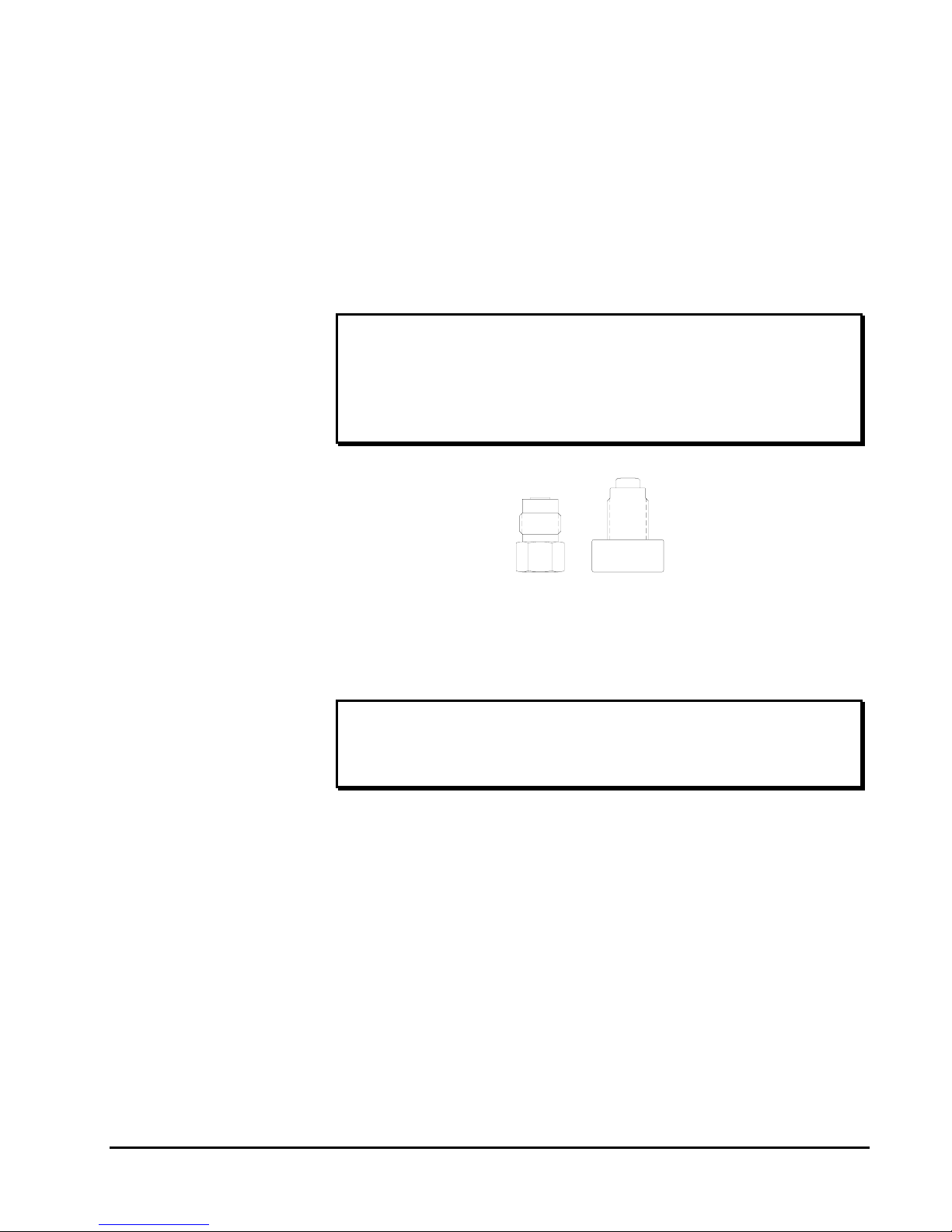
APPENDIX B
EZ GRIP FITTING GUIDE
A-8
Page 47

Scientific Systems Inc.
Warranty Statement
Scientific Systems, Inc. (SSI) warrants that instruments or equipment manufactured by it for a period
thirty-six (36) months from date of shipment to customer, against defects in materials and
workmanship under normal installation, use and maintenance. Expendable items and physical
damage caused by improper handling or damage caused by spillage or exposure to any corrosive
environment are excluded from this warranty. The warranty shall be void for Polyetheretherketone
(PEEK) components exposed to concentrated Nitric or Sulfuric acids which attack PEEK, or
methylene chloride, DMSO or THF which adversely affect UHMWPE seals and PEEK tubing. Any
defects covered by this warranty shall be corrected by replacing or repairing, at SSI’s option, parts
determined by SSI to be defective.
Spare or replacement parts and accessories shall be warranted for a period of 12 months from date of
installation at customer against defects in materials and workmanship under normal installation, use
and maintenance. Defective Product will be accepted for return only if customer returns them to SSI
within thirty (30) days from the time of discovery of the alleged defect, and prior to return, obtains a
Return Goods Authorization (RGA) number from SSI, and provides SSI with the serial number of
each instrument to be returned. Freight costs for the return of defective Product is the responsibility
of SSI. SSI shall specify the freight carrier for returns.
The warranty shall not apply to any Product that has been repaired or altered except by SSI or those
specifically authorized by SSI, to the extent that such repair or alteration caused the failure, or to
Product that has been subjected to misuse, negligence, accident, excessive wear, or other causes not
arising out of a defect in material or workmanship.
The warranty shall not apply to wear items, specifically:
Check Valves Piston and Wash Seals
Pistons Pulse-Damper Diaphragms
Inlet Lines Filter Elements
The following is the exclusive procedure by which to make claims under this warranty. Customer
shall obtain SSI’s oral or written authorization to return the product and receive a Return Goods
Authorization (RGA) number. The Product must be returned with the RGA number plainly visible
on the outside of the shipping container to SSI. It must be securely packed in a rigid container with
ample cushioning material, preferably the original packaging. All claimed defects must be specified
in writing, including the RGA number, with the written claim accompanying the Product. Product
shall be shipped to SSI at customer’s expense. SSI shall bear the expense of return shipment.
If it appears to SSI that any Product has been subjected to misuse, negligence, accident or excessive
wear, or is beyond the warranty period, customer shall be notified promptly. SSI shall notify
customer of its finding and provide an estimate to repair such Product at the then current rates for
parts and service. SSI shall either repair the product per customer’s authorization or shall return
such Product not repaired to customer at customer’s expense. SSI may invoice customer for the
freight costs of any Product shipped back to customer by SSI which is not covered under the
warranty.
Limitations of Warranty. THE FOREGOING WARRANTIES AND LIMITATIONS ARE CUSTOMER’S
EXCLUSIVE REMEDIES AND ARE IN LIEU OF ALL OTHER WARRANTIES, EXPRESS OR
A-9
Page 48

IMPLIED, INCLUDING WITHOUT LIMITATION ANY WARRANTY OF MERCHANTABILITY OR
FITNESS FOR A PARTICULAR PURPOSE.
A-10
 Loading...