


SYNOPSIS
The Entity Percussion Synthesizer is a modern amalgamation of the most important functions to create a wide range of percussive sounds.
Additional functions have been incorporated in order to increase both the versatility in use within a modular environment and broaden the sound
sculpting abilities of the Entity PS itself.
The Entity PS is capable of producing a huge variety of percussive eects including but not limited to: snares, claps, snaps, rim shots, synth
percussion, bass and lead lines and even a new avor of kick drum sounds. As with the Entity BDS, the PS is a complete synthesizer voice focusing
on versatility and high quality, 100% analog sound design.
Please read the manual carefully to enjoy all the benets the Entity Percussion Synthesizer has to oer.
TRIGGER INPUT and PING!
1
The TRIGGER input jack is used to initiate a percussive tone and trigger the main and noise envelopes from the respective decay
generators. Any signal above 1V can be used - not just triggers or gates.
The PING! Button is used to audition a sound without anything patched into the TRIGGER input.
BODY and BODY CV
2
The BODY control emulates the response of a drum head. It is a subtle control and the eect can vary depending on the status of
other parameters like RING and FM levels. The center position is the most tuned response while Tight produces the least resonant,
lowest amplitude and loose produces a abbier, more bass-y sound. BODY CV works best with bipolar voltages but will accept any
polarity CV. The Body Control works as an oset when external CV is used.
MAIN ENVELOPE CONTROLS
3a
The DELAY and DECAY potentiometers control the envelope trigger delay and decay time for the main sound produced by the resonator.
DELAY will add a time lag between the trigger source and actuation of the main sound and respective envelope. As this control is increased to
the right, the delay time increases. Minimum setting produces no delay. This control is very eective as a variant for snare sounds and is crucial
for clap and snap sound design. Control voltages may be patched into the DELAY CV jack for automating this parameter. CV can produce more
of a delay than is capable with just the DELAY control alone. The DELAY control works as an oset when control voltages are utilized.
DECAY controls the envelope decay time for the main sound source. The envelope can be routed to the FM section and automatically controls
the output level of the main sound’s VCA. This control works specically for the main sound source unless the NOISE mode is set to FILTER, in
which case the DECAY controls the overall envelope length, in conjunction with the NOISE controls (see NOISE modes, below). Control
voltages for this parameter are patched into the DECAY jack. The control works as an oset when CV is used.
***For general percussive sounds, nominal position for the DECAY control is from minimum to roughly center of the dial. Use beyond center is
DUCK OUT provides an oset and inverted version of the main envelope for ducking external VCAs.
NOISE LEVEL,MODE and ENVELOPE CONTROLS
3b
The N-DECAY and N-LEVEL potentiometers control the envelope decay time and volume level for the noise generator.
N-DECAY controls the envelope decay time of the dedicated, internal NOISE VCA. Like the main DECAY control, the N-DECAY control oers
somewhat specic use when set to the left or right of center position. Set from minimum position to center, very short decay times are achieved.
This is useful for variations in producing short clicky sounds. For snare and clap sounds, or if a much longer decay time is desired, setting this
control from just below center to maximum is recommended. The control works as an oset when CVs are patched into the N-DECAY input jack
generally for, but not limited to laser and synth eects, bass and lead sounds and external processing.***
rev1.00
PERCUSSION
3a
DELAY
N-DECAYDECAY
2
1
6
11
4
3b
5
NOISE
WHITE
FILTER
3b
PINK
HARMONICS
N-LEVEL
8
7
INT
7
5
DECAY
DELAY
2
3b
N-DECAY
3a
6
HARM CV
8
4
3b
NOISE CV
9
10
N-LEVEL controls the CV depth going into the internal NOISE VCA. The N-DECAY envelope is normalized into NOISE CV via the N-LEVEL
potentiometer. This normalization breaks when a signal is patched into the NOISE CV jack, allowing the noise level to be actuated separately
from the main sound and CV level adjusted via the N-LEVEL control.
NOISE MODE: The NOISE switch selects from 3 types of noise; WHITE, PINK and FILTER, which processes the noise through the main sound
signal chain, including the bandpass resonator, harmonics and main VCA. As stated in section 3a, While the N-DECAY and N-LEVEL controls still
work independently, the main envelope DECAY and OUTPUT control the overall decay and level when FILTER mode is selected.
PITCH and 1V/OCT
4
The PITCH control tunes the tonal frequency of the output. Featuring a large span of control from about 8Hz to roughly 2.2kHz. Both higher and lower frequencies are capable using the 1V/OCT and/or
FM CV inputs. The 1V/OCT input is used for tracking Entity with a sequencer, keyboard or as an additional FM input. The module will reliably track at least four or more octaves.
FM LVL, FM CV and FM SWITCH
5
The FM LVL control is a bipolar attenuator. Center position reduces the modulation depth to zero. Fully right is maximum positive depth, fully left is maximum inverted depth. FM CV jack is used for patching external modulation
sources to frequency modulate the output. The switch below FM LVL has three positions that select the routing to the FM LVL control. The rightmost position selects FM CV only and doubles as an “OFF” selection if no CV is patched
into the FM CV jack. The center position will sum any signal patched into FM CV with the internal MAIN envelope generator. The leftmost position selects the internal MAIN envelope only.
RING and RING CV
6
The RING control aects the resonance and resonant decay time of the output signal. The amount of resonance/decay produced by this function is independent of the other controls. However, using the internal
envelope or external CV to control the amplitude (volume) in the OUTPUT VCA section (see below) can have an aect on how much resonant decay is heard - a useful sound design feature. At maximum setting, RING
will produce a sustained self oscillation. When set to minimum, a small amount of resonance will still be present. The RING CV input is used to modulate the RING function and the RING control works as an oset when
RING CV is in use. For most percussive sounds, RING is typically set to minimum or very low - this is a good starting point, especially for snare sounds. For longer duration sounds and/or more resonance is desired, RING
should be increased to suit.
OUTPUT, AMP CV and SWITCH
7
The OUTPUT control aects the amplitude (volume) of the main resonator sound. When WHITE or PINK noise modes are selected, OUTPUT aects only the volume of the main sound from the resonator. When
noise mode is selected, OUTPUT controls the overall volume of both the main resonator and processed noise. AMP CV jack is provided for external modulation use and will bypass the internal envelope when a signal is
patched into this jack. OUTPUT then controls the level of the applied CV. Plenty of headroom and the signal may be pushed into hard clipping, for a crunchier sound.
The SWITCH below the OUTPUT control aects the mixer going into the main signal chain. An external signal may be combined, or processed independently from the main sound. You may choose between the internal
sound only, external only or a mix of both processed sounds. This greatly enhances the sound possibilities while also providing a fast way to switch between the three sound variants. External sources are patched into the
EXT IN jack (see 10, EXT IN).
POWER CONSUMPTION
QUIESCENT: +61mA, -91mA
MAXIMUM: +72mA, -125mA
MAIN
FILTER
HARMONICS and HARM CV
8
The HARMONICS control adds heavy upper harmonic content to the main sound and/or external sources. This control can have a dramatic aect on percussive sounds as well as bass, lead and synth percussion.
It is in essence, a wavefolder and may be used as such for processing external signals.
Use the HARM CV jack to voltage control the HARMONICS parameter. The control works as an oset when external modulation is used.
OUTPUT
9
Entity PS OUTPUT jack. The main, noise and external signals mixed into the EXT-IN jack are routed here.
EXT-IN
10
EXT-IN is the direct input into Entity’s resonant bandpass lter, harmonics and main VCA . This input is used for a two major functions, described below:
PROCESSING external VCOs, drum modules etc. As mentioned, an external sound source may be processed through Entity’s lter, harmonics and main VCA. All the main controls will aect the sound and behavior of
the externally patched signal. This signal can be processed alone, combined with the internal sound or switched out of the mix using the mix SWITCH below the OUTPUT control.
AUX TRIGGERING resonator with a dierent trigger pattern or source. AUXILIARY triggering is achieved via the EXT IN jack to produce more complex rhythms and dynamics. The eect is sensitive to the pulse-width of
the trigger or gate signal used and therefore provides a way to get even more expressive with your rhythms. The eects can be dramatic and you are encouraged to experiment in order to understand the possibilities.
All the main controls will aect the sound and behavior of the externally patched signal. This signal can be processed alone, combined with the internal sound or switched out of the mix using the mix SWITCH below
the OUTPUT control.
RGB STATUS LED
11
This LED provides visual feedback for the major functions related to the processed signal.
An active trigger is displayed in green. The duration of the green pulse is aected by the BODY control as a faster green blip indicates a tight response and a longer pulse indicates a loose response.
Depth of
frequency modulation
is displayed in
blue
. Whether positive or negative, the level of depth is always indicated by the intensity of the blue portion of the LED.
The output waveform is displayed in red.
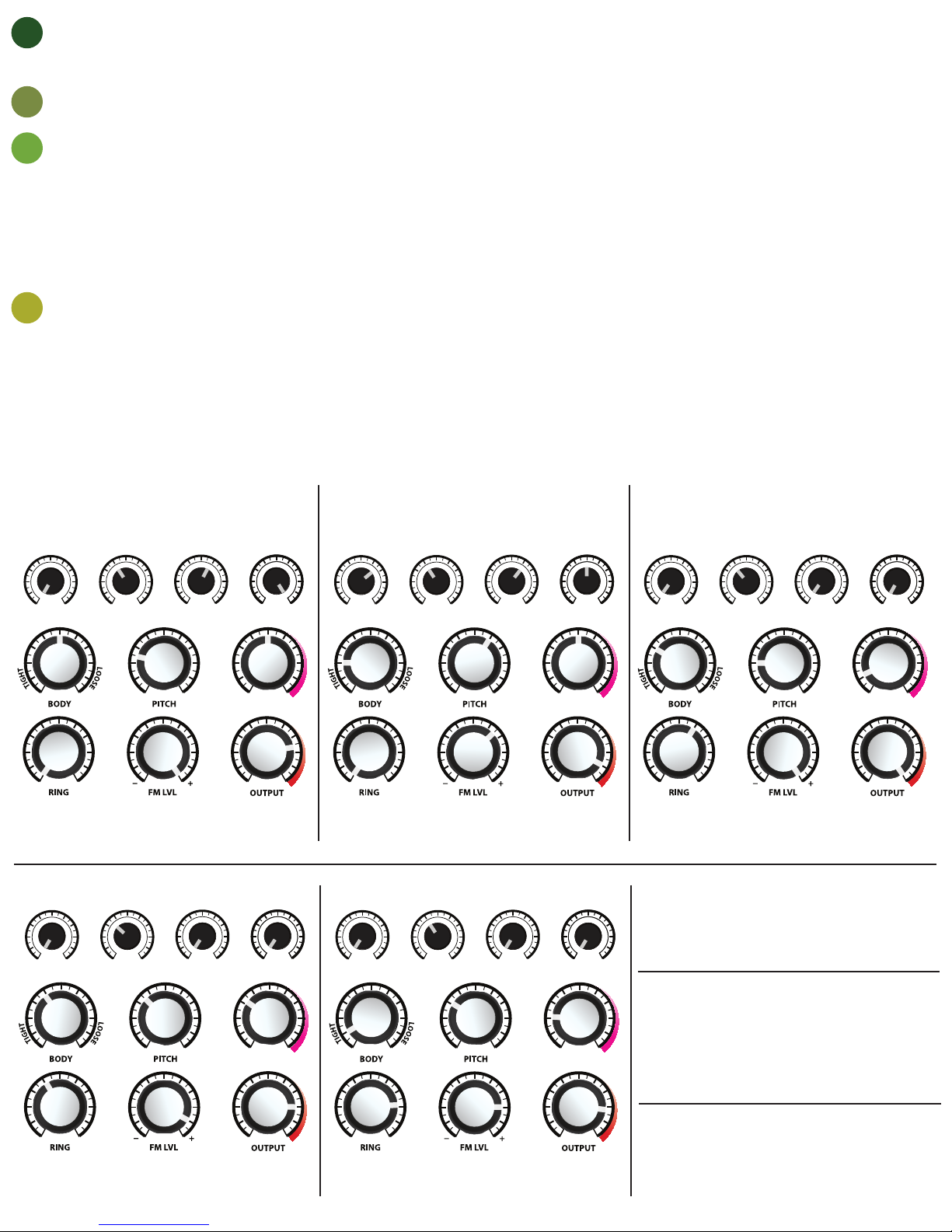
GENERAL PERCUSSION SYNTHESIS EXAMPLES
Here are a few patch examples to be taken as a starting point, and to get you familiar with the Entity Persuasion Synthesizer. Any patch can be further expanded upon using external CV and audio sources.
SNARE
The Entity PS is capable of a very large variety of snare sounds. This
may certainly vary with taste and related program material. Please
experiment with variations of the following patch to grasp the
range of possibilities for snares.
DELAY
N-DECAYDECAY
N-LEVEL
HARMONICS
SWITCH SETTINGS:
NOISE
to WHITE or PINK, FM to ENV or ENV+FM
OUTPUT SWITCH to INT
RIM SHOT
Experiment with HARMONICS, BODY, FM LVL, PITCH and RING
DELAY
N-DECAYDECAY
N-LEVEL
HARMONICS
CLAP
The Entity PS is capable of a very large variety of claps and snaps.
Please experiment with variations of the following patch to grasp
the range of possibilities for claps and snaps.
DELAY
N-DECAYDECAY
N-LEVEL
HARMONICS
SWITCH SETTINGS:
NOISE
to
FILTER
, FM to ENV or ENV+FM
OUTPUT SWITCH to INT
TOM
Experiment with HARMONICS, BODY, FM LVL, PITCH and RING
DELAY
N-DECAYDECAY
N-LEVEL
HARMONICS
KICK
Kicks and similar percussion are possible with the Entity PS.
Please experiment with variations of the following patch to grasp
the range of possibilities for kicks etc.
DELAY
N-DECAYDECAY
N-LEVEL
HARMONICS
SWITCH SETTINGS:
NOISE
to WHITE / PINK for boomier kick or
FILTER
for a tighter kick
FM to ENV or ENV+FM, OUTPUT SWITCH to INT
TOM/BONGO
Achieve more of a bongo sound using the TOM patch and applying
a VCO to FM CV.
SWITCH SETTINGS:
NOISE
to WHITE or PINK, FM to FM CV or ENV+FM
OUTPUT SWITCH to INT or MIX
PERCUSSIVE BASS/LEAD
Follow the KICK patch with increased RING and trim DECAY to suit.
Experiment with HARMONICS and other controls. Optionally apply
a VCO to EXT IN.
SWITCH SETTINGS:
NOISE
to desired pos. , FM to desired pos.
OUTPUT SWITCH to INT, MIX or EXT
SWITCH SETTINGS:
NOISE
to WHITE or PINK or to
FILTER
for a tighter (808/909) sound
FM to ENV or ENV+FM
OUTPUT SWITCH to INT
SWITCH SETTINGS:
NOISE
to WHITE or PINK, FM to ENV or ENV+FM
OUTPUT SWITCH to INT
NOISE HATS+
Noise can be processed separately in any patch via the NOISE CV jack.
Therefore, one can trigger both a percussive aect and separately
controlled hi-hat simultaneously. Adjust CV level using N-LEVEL
SWITCH SETTINGS:
NOISE
, FM, OUTPUT SWITCH (patch dependent)
 Loading...