

SYNOPSIS
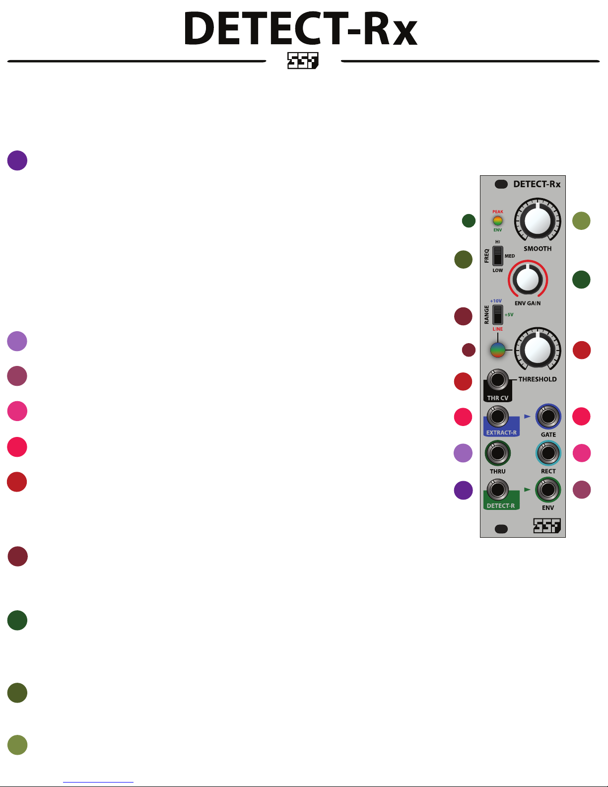
DETECT-Rx oers three useful synthesizer functions including a versatile envelope follower (DETECT-R), voltage controlled gate extractor (EXTRACT-R) and signal rectier (RECT).
The DETECT-R provides advanced features compared to typical envelope followers with the addition of a detection frequency select switch, manual smoothing lter and attenuation/gain control.
The EXTRACT-R provides both manual and CV attenuated control over signal threshold levels for gate extraction. Three selectable signal ranges are available to accommodate all signal types, including line level signals.
RECT is a positively rectied signal output that will also accommodate all signal levels. Rectication is useful for both CV and audio. You can turn bipolar signals into positive signals or create octave up eects and 2nd
harmonic distortion among other uses.
Please read the manual carefully to understand the module functions and get the best use out of the DETECT-Rx.
DETECT-R INPUT and NORMALIZATION
1
This is the input to the DETECT-R, a versatile envelope follower. The DETECT-R will transform signals into time varying control voltages that follow the
amplitude level of the input signal. Controls for the DETECT-R are explained in sections 8-10, below.
The input signal is buered to the THRU output (section 2) for routing to another module without the need for a multiple. For example, patch a dynamic
mix into the DETECT-R, THRU out to a VCF’s signal input, and ENV out to the VCF’s CV input.
The DETECT-R input is also the input to the rectication circuit (RECT, section 4).
NORMALIZATION:
In addition to the direct routing scheme explained above, the DETECT-R input will route to the gate EXTRACT-R when nothing is patched into the EXTRACT-R
input. This allows for all DETECT-Rx functions to be used simultaneously from a single signal input. Otherwise, the DETECT-R and EXTRACT-R may be used
exclusively.
Similarly, the GATE output is normalized into the DETECT-R input when nothing is patched into the DETECT-R. The normalized gate signal routes into the
DETECT-R to provide a simultaneous GATE and gated envelope out. The envelope shape is aected by the EXTRACT-R controls as well as the gate length,
which is adjustable via the THRESHOLD control.
THRU
2
Provides a buered copy of the signal applied to the DETECT-R input.
8
9
7
7
10
8
6
ENVELOPE OUTPUT
3
This is the DETECT-R’s envelope follower output.
RECTIFIER OUTPUT
4
All signals patched into the DETECT-R are rectied and sent to the RECT output jack.
GATE EXTRACT-R
5
INPUT and OUTPUT of the threshold based gate extractor. See section 1, above for normalization scheme when solely using the EXTRACT-R input.
6
THRESHOLD and THR CV
The knob controls the voltage threshold level. At minimum, the gate will re for all signals above 0V (zero volts). At maximum, the gate will re at the voltage
level determined by the RANGE switch, described in section 7, below.
A control voltage may be used as a dynamic threshold control when patched into the THR CV input. The knob controls the CV depth when CV is applied to this
input.
EXTRACT-R RANGE SWITCH and LED
7
The RANGE switch provides three common levels that set the maximum span of the threshold control.
10V - best when extracting gates from external envelopes and louder signals - BLUE LED
5V - typical range for extracting gates from common modular audio signal levels - GREEN LED
LINE - for consumer line level instruments such as synthesizers, desktop boxes and eects. Can also accommodate louder guitar pick-ups. Some gain staging may be necessary for lower level instruments - RED LED
ENV LEVEL CONTROL and LED
8
Controls the gain of the output ENV of the DETECT-R. Largely dependent on the signal level applied to the DETECT-R input, this control will accommodate just about any signal level. Signals can be both attenuated and
amplied using this control. You may choose to use this control in conjunction with external CV input attenuators, or as the sole envelope CV depth control.
The LED indicates an active envelope shown in GREEN. The envelope peak is indicated in ORANGE - this indicates that the envelope has reached it’s clipping level. Peaking is not a bad thing unless the LED is constantly
ORANGE - which indicates that the signal is constantly at maximum level - this will result in very little dynamic content but will not do any harm.
6
5
2
1
5
4
3
FREQUENCY RANGE SWITCH
9
One of the most useful features of the DETECT-Rx, the FREQ range switch allows you to select three frequency bands that the envelope follower will sense from the input signal and create dynamic transients that follow
the selected frequency band. In general, HI produces fast transients as it follows the high frequency content of a signal, MED is a bit slower as it follows the mid bands and LOW produces longer transients as it follows
the low bands and overall emphasis of the input signal.
SMOOTH
10
This manual smoothing lter adds an additional transient shaping function to the DETECT-R envelope follower circuitry. Essentially a low pass lter that scales appropriately to the selected frequency band, this control
can smooth out the ripple commonly associated with envelope followers as well as provide a means for ne tuning the desired envelope output for a wide variety of expressive transient shapes.

WHAT IS SIGNAL RECTIFICATION?
The graph to the right illustrates the function of DETECT-Rx’s signal rectier.
FIGURE (a.) Shows an example bipolar input signal from the Triangle output of a VCO. The BLUE arrows highlight the negative
portion of this bipolar signal. Note the entire region from 0V to -5V.
FIGURE (b.) Shows the rectied output. The RED arrows highlight the previously negative region of the Triangle waveform in
FIGURE (a.)
They are now ipped (rectied) into the positive voltage region.
+5V
Notice that the rectied signal is now twice the frequency of the input signal. This is the typical function of ‘octave up’ guitar
eects and can also be used for the same function in a modular synthesizer.
Also try using the rectier on a total mix or external audio for extreme 2nd harmonic (even ordered) distortion eects.
OTHER COMMON USES:
Not all control voltages are compatible.
For instance, there are modules that produce bipolar control voltages and modules that only accept positive control voltages.
Therefore, a bipolar CV will only aect a positive CV input when the input signal is positive.
A rectier can be used to convert bipolar or even completely negative CV into a full range positive control voltage.
WHAT IS GATE EXTRACTION?
The graphs to the right illustrate the function of DETECT-Rx’s gate extractor. The examples show a Triangle wave in GREY as
the input to the EXTRACT-R.
For this example, we will consider that the RANGE switch set to 5 or 10V.
The broken GREEN line is a graphical representation of various threshold settings of 0-60%.
The BLACK waveforms illustrate the output gate for the respective threshold levels, explained below.
FIGURE (c.) Shows the threshold set to 0V (zero volts). Notice that the gate goes high for the entire duration that the input
waveform is positive.
FIGURE (d.) Shows the threshold set to roughly 2.5V. Notice that the gate is more narrow in this example because the region
above the threshold is also more narrow.
FIGURE (e.) Shows the threshold set to roughly 4.5V. As expected, the gate is now very thin and fast, behaving like a trigger.
A trigger is simply just a very fast gate.
FIGURE (f.) Shows the threshold set to beyond the region where the input signal is active. Since there is no signal voltage
that reaches this threshold setting, there will be no gate or trigger output.
-5V
+10V
+5V
-5V
+10V
+5V
-5V
0V
a. b.
(+/-5V input signal) (+5V rectied output)
0V
c.
0V
e.
d.
f.
A FEW EXTRACT-R USES:
Extract a gate clock from audio or drum machines to time events within a modular system.
Create delayed gates and triggers from slower control voltages such as LFOs and Envelopes.
Convert any signal from a VCO into a pulse. Use a Sine, Triangle or any sloped waveform as a control voltage into THR CV to time vary the pulse width (Pulse Width Modulation.)
Produce extremely heavy distortion when patching audio into the EXTRACT-R input.
Utilize the GATE output normalization into the DETECT-R to create an adjustable slew gate (gated envelope).
Create threshold based events within a complex patch.
Boost 5V and low level gates and triggers up to 10V.
WHAT IS AN ENVELOPE DETECTOR?
An Envelope Detector follows the amplitude dynamics of a given input signal. The output is a positive control voltage that can be used to modulate any parameter in a modular system. Since the output CV follows the input signal’s
amplitude levels, an Envelope Detector is also commonly referred to as an Envelope Follower.
The DETECT-R includes special features for greater control of the output envelope shape. The FREQ select switch provides three signal bands to choose from, allowing for ner control of the output signal based on the input
frequency content. The gures below illustrate the general envelope shapes for the relevant frequency bands. Envelope outputs are shown in GREEN, Peak level shown in ORANGE.
The SMOOTH control adds an additional 6 dB low pass lter that will alter the attack and decay respinse of the output and smooth the ripples, for example, as seen in the ‘HI’ gure, below. The cuto frequency of the SMOOTH lter
scales to the selected frequency band, which allows the DETECT-R to be tuned across the entire audio spectrum.
HI MED LOW
+10V
+5V
0V
-5V
GAIN/ATTENUATION
A FEW DETECT-R USES:
Side chaining
Dynamics processing
Signal processing
Slewing control voltages
Gated envelope generation
POWER CONSUMPTION
QUIESCENT: +29mA, -29mA
MAXIMUM: +47mA, -44mA
 Loading...