

SSE SS26, SS23, SS25, SS24, SS22 Datasheet
SHANGHAI SUNRISE ELECTRONICS CO., LTD.
)
(
)
)
(
)
)
SS22 THRU SS26
SURFACE MOUNT SCHOTTKY
BARRIER RECTIFIER
VOLTAGE: 20 TO 60V CURRENT: 2.0A
FEATURES
• Ideal for surface mount pick and
place application
• Low profile package
• Low power loss, high efficiency
• High current capability,low V
• High surge capability
• High temperature soldering guaranteed:
o
260
C/10sec/at terminal
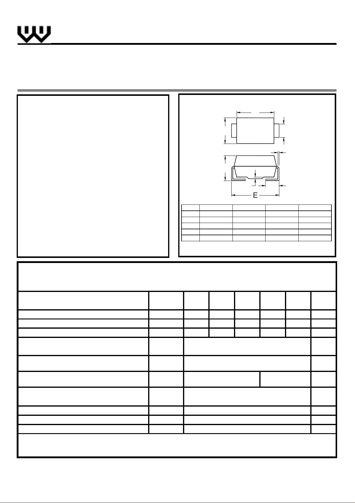
MECHANICAL DATA
• Terminal: Plated leads solderable per
MIL-STD 202E, method 208C
• Case: Molded with UL-94 Class V-O
recognized flame retardant epoxy
• Polarity: Color band denotes cathode
F
MAX. .155
MIN. .130(3.30).160(4.06).077(1.96).006(0.152
MAX. .220
MIN. .205(5.21).084(2.13).004(0.102).030(0.76
TECHNICAL
SPECIFICATION
SMB/DO-214AA
B
A
F
G
ABCD
3.94).180(4.57).083(2.11).012(0.305
EFGH
5.59).096(2.44).008(0.203).060(1.52
Dimensions in inches and (millimeters
C
D
H
MAXIMUM RATINGS AND ELECTRICAL CHARACTERISTICS
(Single-phase, half-wave, 60Hz, resistive or inductive load rating at 25oC, unless otherwise stated, for capacitive load,
derate current by 20%)
RATINGS
Maximum Repetitive Peak Reverse Voltage
Maximum RMS Voltage
Maximum DC Blocking Voltage
Maximum Average Forward Rectified Current
(T
=100oC)
L
Peak Forward Surge Current (8.3ms single
half sine-wave superimposed on rated load)
Maximum Instantaneous Forward Voltage
(at rated forward current)
Maximum DC Reverse Current
(at rated DC blocking voltage)
Typical Junction Capacitance (Note 1)
Typical Thermal Resistance (Note 2)
Storage and Operation Junction Temperature
Note:
1.Measured at 1.0 MHz and applied voltage of 4.0V
2.Thermal resistance from junction to terminal mounted on 5×5mm copper pad area
T
=25oC
=100oC
T
a
SYMBOL
V
RRM
V
RMS
V
DC
I
F(AV)
I
FSM
V
F
I
R
C
J
R
(ja)
θ
T
STG,TJ
dc
SS22 SS23 SS24 SS25 SS26
20 30 40 50 60 V
14 21 28 35 42 V
20 30 40 50 60 V
2.0 A
50
0.5 0.7
0.5
10.0
200
25
-65 to +150
http://www.sse-diode.com
UNITS
A
V
mA
mA
pF
o
C/W
o
C
 Loading...