


Series
Manual für Erst - Inbetriebnahme

Intelligentes Bedienterminal
Intelligent Operator Terminal
Typ: IBT
Erstinbetriebnahme
Getting started
Erstinbetriebnahme Typ: IBT V02.24TB99 (UL: 9.5.2) 2 Getting Started Model: IBT V02.24TB99 (UL: 9.5.2)

Weitere Unterlagen, Further descriptions,
die im Zusammenhang mit that relate to this document.
diesem Dokument stehen.
UL: 7.1.8.2
631 - Produkt-Handbuch
635 - Produkt-Handbuch
637 - Produkt-Handbuch
IBT - Produkt-Beschreibung
IBT - Technisches Handbuch
631 - Product manual
UL: 7.1.5.6
635 - Product manual
UL: 7.2.8.3
637 - Product manual
UL: 9.5.1
IBT - Product description
UL: 9.5.3
IBT - Technical manual
ã EUROTHERM Antriebstechnik GmbH.
Alle Rechte vorbehalten. Kein Teil der Beschreibung darf
in irgendeiner Form, ohne Zustimmung der Gesellschaft
vervielfältigt oder weiter verarbeitet werden.
Änderungen sind ohne vorherige Ankündigung
vorbehalten.
EUROTHERM hat für seine Produkte teilweise Warenzeichenschutz und Gebrauchsmusterschutz eintragen
lassen. Aus dem Überlassen der Beschreibungen darf
nicht angenommen werden, daß damit eine Übertragung
von irgendwelchen Rechten stattfindet.
Hergestellt in Deutschland, 1998
Erstinbetriebnahme Typ: IBT V02.24TB99 (UL: 9.5.2) 3 Getting Started Model: IBT V02.24TB99 (UL: 9.5.2)
ã EUROTHERM Drives Limited.
All rights reserved. No portion of this description may
be produced or processed in any form without the
consent of the company.
Changes are subject to change without notice.
EUROTHERM has registered in part trademark
protection and legal protection of designs. The handing
over of the descriptions may not be construed as the
transfer of any rights.
Made in Germany, 1998

INHALTSVERZEICHNIS
Seite
1 Allgemeines........................................................................................................................... 6
1.1 Beschreibung....................................................................................................................... 6
1.2 Benötigte Komponenten...................................................................................................... 6
1.2.1 Hardware ........................................................................................................................ 6
1.2.2 Kabel............................................................................................................................... 6
1.2.3 Software.......................................................................................................................... 6
1.3 Systemvoraussetzungen....................................................................................................... 6
1.3.1 Verdrahtung.................................................................................................................... 6
1.3.2 Servoregler 630 - Serie................................................................................................... 7
1.3.3 IBT.................................................................................................................................. 7
1.3.4 Projektordner .................................................................................................................. 7
2 Die erste Applikation........................................................................................................... 8
2.1 Notwendige Arbeiten auf dem Servoregler......................................................................... 8
2.1.1 Einstellung der CAN-Bus Parameter.............................................................................. 8
2.1.2 Laden des BIAS-Programms .......................................................................................... 9
2.2 Notwendige Arbeiten auf dem IBT..................................................................................... 9
2.2.1 Laden des Demoprojekts ................................................................................................ 9
2.2.2 Aktivieren des Downloadmodus .................................................................................. 10
3 Beschreibung des Demoprojektes .................................................................................... 12
4 Hinweise zur Fehlersuche ................................................................................................. 13
4.1 Kommunikationsfehler...................................................................................................... 13
4.2 Funktionsfehler.................................................................................................................. 14
5 Anschlußbelegung.............................................................................................................. 15
5.1 Schirmung ......................................................................................................................... 15
5.2 Schnittstellen..................................................................................................................... 15
5.2.1 Steckerbelegung X1 Versorgungsspannung................................................................. 15
5.2.2 Pin-Belegung CAN-Schnittstelle IBT und Servo ......................................................... 16
5.2.3 Programmierschnittstelle X3 RS232 ............................................................................ 16
6 Index ................................................................................................................................... 17
Erstinbetriebnahme Typ: IBT V02.24TB99 (UL: 9.5.2) 4 Getting Started Model: IBT V02.24TB99 (UL: 9.5.2)

CONTENTS
Page
1 General ................................................................................................................................18
1.1 Description ........................................................................................................................18
1.2 Required Components .......................................................................................................18
1.2.1 Hardware...................................................................................................................... 18
1.2.2 Cable............................................................................................................................. 18
1.2.3 Software ........................................................................................................................ 18
1.3 System requirements.......................................................................................................... 18
1.3.1 Wiring ........................................................................................................................... 18
1.3.2 Servo drive 630 series................................................................................................... 19
1.3.3 IBT ................................................................................................................................19
1.3.4 Project directory ........................................................................................................... 19
2 The first application............................................................................................................ 20
2.1 Necessary operations on the servo drive........................................................................... 20
2.1.1 Adjustment of the CAN-Bus Parameter ........................................................................ 20
2.1.2 Load BIAS-Program ..................................................................................................... 21
2.2 Necessary operations on the IBT....................................................................................... 21
2.2.1 Load the demo project ..................................................................................................21
2.2.2 Activate the download mode .........................................................................................22
3 Description of the Demo project .........................................................................................24
4 Troubleshooting ..................................................................................................................25
4.1 Communication errors....................................................................................................... 25
4.2 Operational errors............................................................................................................. 26
5 Connector pin assignment ..................................................................................................27
5.1 Shielding ............................................................................................................................27
5.2 Interfaces ........................................................................................................................... 27
5.2.1 Connector pin assignment X1 supply voltage............................................................... 27
5.2.2 Pin assignment X2.1/2 CAN interface IBT and Servo .................................................. 28
5.2.3 Programming port X3 RS232 .......................................................................................28
6Index....................................................................................................................................29
Erstinbetriebnahme Typ: IBT V02.24TB99 (UL: 9.5.2) 5 Getting Started Model: IBT V02.24TB99 (UL: 9.5.2)

1 Allgemeines
1.1 Beschreibung
Das Intelligente Bedien-Terminal IBT vereinfacht die Ein- und Ausgabe von Prozeßgrößen für den
Anwender. Eine komfortable Bedienung wird durch die Integration des TesiMod-Bedienkonzeptes
erreicht.
Die Kommunikation zwischen dem IBT und dem Regler erfolgt über die CAN - Schnittstelle.
1.2 Benötigte Komponenten
1.2.1 Hardware
Numerierung Artikelnummer
IBT - Bedienterminal (Ausführung HF000522)
betriebsbereiter Servoregler (631, 635 oder 637) mit
CAN - Schnittstelle (z.B. Vorführkoffer; Artikelnummer)
24V-Netzteil zur IBT-Versorgung
1.2.2 Kabel
CAN - Verbindungskabel vom Servoregler (COM 2, oder X21)
zum IBT X2.1Anschluß inkl. Abschlußwiderständen
24 V Versorgungskabel zum IBT X1
Programmierkabel PC - IBT X3 KK.5100.1401
Programmierkabel PC - Servoregler KK.5004.0001
Q
R
S
T
Numerierung Artikelnummer
U
BE.1000.1801
ZU.2890.0001
Fremdprodukt
KK.5100.1301
1.2.3 Software
Numerierung Artikelnummer
EASYRider Software V 5.10 auf PC installiert SO.0930.0002
IBT - Programmiersoftware TesiMod V 5.31 auf PC installiert SO.9000.0001
IBT - Demodiskette SO.9000.0101
1.3 Systemvoraussetzungen
1.3.1 Verdrahtung
Verdrahten Sie die Geräte entsprechend dem unten skizzierten Verdrahtungsschema.
4
2
5
1
Erstinbetriebnahme Typ: IBT V02.24TB99 (UL: 9.5.2) 6 Getting Started Model: IBT V02.24TB99 (UL: 9.5.2)

Sind das IBT und der Servoregler im Auslieferzustand1 sollten nach dem Einschalten der Geräte (24VSpannungsversorgung) auf dem IBT folgende Bildschirme nacheinander sichtbar werden:
1. 2. 3.
Fremd-Produkte
Eurotherm-Produkte
Regler 635
IBT-Rückseite
AC Mn
1.3.2 Servoregler 630 - Serie
Der Servoregler muß in der Betriebsart 5 „Lageregelung mit BIAS-Abarbeitung“ arbeiten.
Die Konfiguration und Parametrierung des Verstärkers erlaubt den Betrieb mit dem angeschlossenen
Motor (ohne Mechanik).
1.3.3 IBT
1.3.3.1 DIP-Schalter Die DIP-Schalter des IBT (linke Seitenwand) müssen folgende Stellung haben:
Schalter Ein (ON) Aus (OFF)
S1
Standardmodus
S2 nicht benutzt
S3 Demomodus
(ohne Kommunikation)
S4 Flash-Speicher
komplett löschen
Transparentmodus
nicht benutzt
Kommunikation mit
dem Servoregler
Flash-Speicherdaten
erhalten
1.3.4 Projektordner
Kopieren Sie das Verzeichnis „IBT-Demo“ der Demodiskette inklusive der enthaltenen Dateien auf
eine lokale Festplatte.
1
IBT mit geladenem Default-Projekt; Servoregler mit Defaultwerten in der CAN-Feldbuskonfiguration
Erstinbetriebnahme Typ: IBT V02.24TB99 (UL: 9.5.2) 7 Getting Started Model: IBT V02.24TB99 (UL: 9.5.2)
2 Die erste Applikation
Um Ihnen die Arbeit zu erleichtern, haben wir auf der Demodiskette eine erste Applikation für Sie
vorbereitet.
Um die Applikation abarbeiten zu können müssen Sie Einstellungen am Servoregler und am IBT
vornehmen.
2.1 Notwendige Arbeiten auf dem Servoregler
Alle nun folgenden Arbeiten werden mit der Programmier- und Diagnoseoberfläche EASYRider über
die serielle Verbindung zum Servoregler ausgeführt.
Wichtiger Hinweis
Um die Verbindung zum Verstärker zu testen aktivieren Sie bitte als ersten Schritt nach dem Starten
des EASYRider die Funktion „Diagnose“, „Reglerdiagnose“ (oder Sie betätigen die Taste „F9“).
Achten Sie bitte auf die am Bildschirm rechts unten angegebene Schnittstelle. Dort sollte nicht der
Zusatz „simuliert“ erscheinen. Falls doch schalten Sie bitte die Simulation unter „Optionen“,
„ Kommunikation simulieren“ aus und gehen anschließend zur Funktion „Reglerdiagnose“.
Nachdem die Kommunikation erfolgreich überprüft wurde, verlassen Sie bitte die Reglerdiagnoseseite
durch die Betätigung der Taste „ESC“.
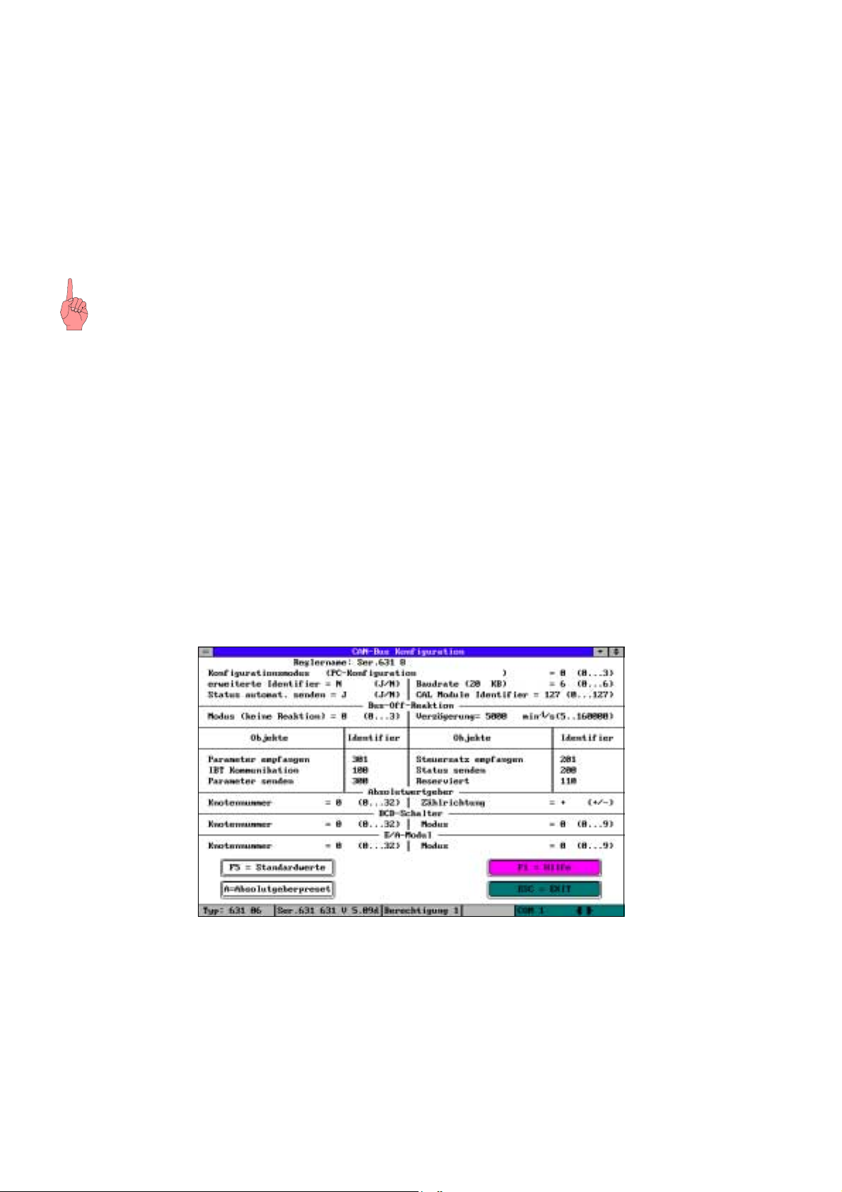
2.1.1 Einstellung der CAN-Bus Parameter
Um die CAN-Bus Parameter einstellen zu können aktivieren Sie die Funktion „Konfiguration“,
„Feldbusmodul“ und gehen folgendermaßen vor:
• Geben Sie mindestens das Paßwort der Berechtigungsstufe 1 ein.
• Bestätigen Sie die Abfrage der PC-Anmeldung mit „Ja“.
• Bestätigen Sie die Abfrage der Reglerdeaktivierung mit „Ja“.
Sie sollten nun folgenden Bildschirm vor sich sehen.
CAN-Feldbuskonfiguration
• Betätigen Sie die Taste „F5“ (Standardwerte).
• Verlassen Sie die Konfigurationsseite durch die Betätigung der Taste „ESC“.
• Bestätigen Sie die Abfrage „Änderungen übernehmen?“ mit „Ja“.
• Bestätigen Sie die Abfrage „Alle Daten speichern?“ und alle folgenden mit „Ja“.
Erstinbetriebnahme Typ: IBT V02.24TB99 (UL: 9.5.2) 8 Getting Started Model: IBT V02.24TB99 (UL: 9.5.2)

2.1.2 Laden des BIAS-Programms
• Wechseln Sie in den BIAS-Editor („BIAS“, „BIAS-Editor“).
• Laden Sie das BIAS-Programm „Demo_1D.ASB“ aus dem Projektverzeichnis (Menü „Datei“,
„BIAS-Programm laden“ oder Taste „F2“).
• Übertragen Sie dieses Programm an den Verstärker (Menü „Programm“, „BIAS-Programm
senden“ oder Taste „F4“).
• Speichern Sie das BIAS-Programm auf dem Verstärker. Beantworten Sie dazu die entsprechenden
Abfragen mit „Ja“.
2.2 Notwendige Arbeiten auf dem IBT
Die folgenden Arbeiten werden mit der IBT - Programmiersoftware TesiMod über die
Programmierschnittstelle X3 des IBT ausgeführt.
Wichtiger Hinweis
Bitte beachten Sie die Besonderheiten von Multitasking-Betriebssystemen (z.B. Windows 95, 98) bei
der Verwaltung von seriellen Schnittstellen.
Falls Sie beide Programme parallel abarbeiten (getrennte MS-DOS-Fenster), müssen beide Programme
unterschiedliche serielle Schnittstellen des PC benutzen (z.B. EASYRider COM1 und TesiMod
COM2). Gleiches gilt auch für die mehrfache Abarbeitung eines der beiden Programme.
2.2.1 Laden des Demoprojekts
Führen Sie die Funktion „Datei“, „Projekt laden“ aus.
Wechseln Sie in den Projektordner und wählen Sie die Datei „IBT1DEMO.PRJ“ aus.
Führen Sie die Projektverwaltung (Menü „Bearbeiten“, „Projektverwaltung“ oder Taste „F4“) aus
Sie sollten nun folgenden Bildschirm vor sich sehen.
Aktivieren Sie die Downloadfunktion unter „Bearbeiten“, „Download“, oder Taste F6.
Erstinbetriebnahme Typ: IBT V02.24TB99 (UL: 9.5.2) 9 Getting Started Model: IBT V02.24TB99 (UL: 9.5.2)

Überprüfen Sie die verwendete serielle Schnittstelle unter "Bearbeiten“, „COMx-Schnittstelle“
(Auswahl mit der Leertaste und anschließender Betätigung der Enter-Taste).
Aktivieren Sie den Downloadmodus des IBT (siehe Kapitel 2.2.2).
Starten Sie die Downloadfunktion mit der Taste F6.
2.2.2 Aktivieren des Downloadmodus
Der Downloadmodus des IBT-Bedienfeldes ist die Voraussetzung zum Laden eines Projektes.
Es gibt zwei grundsätzliche Wege das Bedienfeld in den Download-Modus zu schalten.
1. über die DIP-Schalter des Bedienfeldes
2. über die Setup-Maske (bzw. andere programmierte Eingabemasken) des geladenen Projektes
Wichtiger Hinweis
Nachdem der Downloadmodus aktiviert wurde muß ein Projekt geladen werden, d.h. das aktuelle
Projekt wird gelöscht. Auch das Aus- und Einschalten des IBT stellt den Ausgangszustand nicht
wieder her.
2.2.2.1 Aktivieren des Downloadmodus über die DIP-Schalter
Schalten Sie bei ausgeschaltetem IBT den DIP-Schalter 4 auf die Stellung ON.
Schalten Sie das IBT ein. Die folgende Maske sollte auf dem IBT dargestellt werden:
Schalten Sie nun den DIP-Schalter 4 auf die Stellung OFF.
Das Bedienfeld beginnt mit dem Löschen des Flash-Speichers ( ) und schaltet anschließend
in den Downloadmodus ( ).
Das Bedienfeld ist nun bereit die Daten des neuen Projekts zu empfangen.
Erstinbetriebnahme Typ: IBT V02.24TB99 (UL: 9.5.2) 10 Getting Started Model: IBT V02.24TB99 (UL: 9.5.2)

2.2.2.2 Aktivieren des Downloadmodus über die Setup-Maske
Im Gegensatz zur ersten Möglichkeit ist es bei dieser zweiten Möglichkeit erforderlich, daß bereits ein
Projekt geladen wurde und in der Setup-Maske eine entsprechende Möglichkeit programmiert wurde.
Um in die Setup-Maske zu gelangen, müssen Sie während der Anzeige der
Startmaske ( für ca. 5s) die Taste „Enter“( ) betätigt haben.
Das Bedienfeld wechselt dann in die Setup-Maske ( ).
Betätigen Sie die Taste „Datenfreigabe“ ( ).
Wählen Sie über die +/- Tasten den Wert „Ja“ an und bestätigen Sie diese Auswahl mit der Taste
„Enter“.
Das Bedienfeld beginnt mit dem Löschen des Flash-Speichers ( ) und schaltet anschließend
in den Downloadmodus ( ).
Das Bedienfeld ist nun bereit die Daten des neuen Projekts zu empfangen.
Wichtiger Hinweis
Betätigen Sie die Taste „Enter“ mit der Auswahl „Nein“ wird das aktuelle Projekt nicht gelöscht und
die Setup-Maske geschlossen.
Erstinbetriebnahme Typ: IBT V02.24TB99 (UL: 9.5.2) 11 Getting Started Model: IBT V02.24TB99 (UL: 9.5.2)

3 Beschreibung des Demoprojektes
Die hier dargestellten Flußpläne geben den Ablauf des Demoprojektes wieder.
1
24 V
einschalten
INITIALIZING
CPU 10 MHz
Eurotherm Antriebe
Im Sand 14
76669 Bad Schönborn
Tel.: +49 7253 94040
nach 5 Sekunden
automatisch
IBT Beispiel
> Einrichten
Automatik
Parameter
IBT Beispiel
Einrichten
> Automatik
Parameter
IBT Beispiel
Einrichten
Automatik
> Parameter
Eurotherm Antriebe
Setup-Maske
Download-Freigabe: 0
Sprache: Deutsch
1
2
3
Vist 0U/Min
Istpos. 1000
- Fahre +
Fahre negativ
so lange gedrückt
2
Automatik
V ist 0 U/Min
Istpos. 1000
Start
3
Parameter 1
Pos 1= 25000 Ink
Pos 2= 7500 Ink
V = 500 U/Min
Einrichten
Fahre positiv
so lange gedrückt
Automatik
V ist 0 U/Min
Istpos. 1000
Stop
Ende
Parameter 2
Beschleun. = 25000
Verzögerung= 5000
Wartezeit = 500 ms
Ende
Ende
Dieses Beispiel zeigt Ihnen wie Sie mit einfachen Mitteln die Umschaltung zwischen 2 Betriebsarten
(Einrichten und Automatik) realisieren und die dafür benötigten Parameter eingeben können.
In der Betriebsart „Einrichten“ (siehe ) ist es möglich die Motorwelle in positiver (F5) oder negativer
Richtung (F2) zu bewegen.
In der Betriebsart „Automatik“ (siehe ) bewegt sich die Motorwelle (F2 = Start, F2 = Stop) von der
Sollposition 1 zur Sollposition 2 und zurück.
Diese zwei Parametrierungsbildschirme (siehe ) dienen der Eingabe der Automatikparameter.
Erstinbetriebnahme Typ: IBT V02.24TB99 (UL: 9.5.2) 12 Getting Started Model: IBT V02.24TB99 (UL: 9.5.2)

4 Hinweise zur Fehlersuche
4.1 Kommunikationsfehler
Wird nach der Anzeige der IBT-Startmaske bzw. während des Betriebs eine Fehlermaske
(z.B. ) angezeigt, können Sie die Fehlerursache anhand des angezeigten Code und
Subcode feststellen.
Fehlermeldungen mit dem Code 50 deuten dabei auf eine fehlerhafte Verdrahtung bzw. fehlerhafte
Parametrierung des IBT bzw. des Servoreglers (Feldbusparameter) hin.
Fehlermeldungen mit dem Code 51 treten bei Speichern der Parameter im Flash-Speicher des
Servoreglers auf. Diese Meldung ist normal und wird nur für die Zeit des Speicherns angezeigt.
Code Subcode Name Erklärung
1 E_SLAVE_NOT_READY Slave zur Zeit nicht bereit
2 E_PROTOCOL Reihenfolge der Pakete fehlerhaft
3 E_FRAME Protokollrahmenfehler
4 E_TIMEOUT Zeitüberschreitung
5 E_CRC_BCC CRC-Fehler
6 E_PARITY Paritätsfehler
7 E_SEND_ABBORT Sendeabbruch
8 R_REC_ABBORT Empfangsabbruch
9 E_BUF_SIZE Zyklischer Puffer zu klein
10 E_NO_DEFINE Keine Zyklischen Daten definiert
12 E_DEFINE Zyklische Daten bereits definiert
15 E_NO_PROTOCOL Gewähltes Protokoll wird nicht unterstützt
16 E_OVERRUN Empfangsüberlauf
40 E_SYS_ADDRESS Undefinierte Systemvariable
50 E_CAN_ERROR Fehler aus dem CAN-Controller
1 Stuff-Error
2, 3 Terminal hat keine Verbindung zum Bus
Am Bus sind keine Teilnehmer angeschlossen
Teilnehmer arbeiten mit anderer Baudrate
4, 5 Busleitung hat Schluß nach logisch 0 oder 1
Abschlußwiderstände fehlen
6 CRC-Fehler
51 E_RESPONSE_TIMEOUT Keine Antwort vom Kommunikationspartner
Kein Partner für Requestobjekt
Kein Empfänger für gesendeten Identifier
53 E_NO_RESPONSE_BIT Falsches Responseobjekt
Nachricht ohne Response-Bit
54 E_RESPONSE OF
NO_REQUEST
55 E_NO_HARDWARE Terminal findet keine CAN-Hardware
60 E_RESET_FROM_MASTER NMT 0 Message mit Kommando 129
100 E_DATA_ERROR Fehler vom Kommunikationspartner
Falsches Responseobjekt
Response ohne Request
CAN-Hardware in Terminal fehlt oder ist defekt
Fehlernummer steht im Subcode
Subcode ist frei definierbar
Erstinbetriebnahme Typ: IBT V02.24TB99 (UL: 9.5.2) 13 Getting Started Model: IBT V02.24TB99 (UL: 9.5.2)

4.2 Funktionsfehler
Sollte die Applikation entsprechend der Beschreibung im Kapitel 3 abgearbeitet werden (Bildschirme
werden ordnungsgemäß angezeigt, der Wechsel zwischen den Bildschirmen ist wie beschrieben
möglich) aber sich der Motor nicht bewegen liegt das Problem wahrscheinlich in der BIASAbarbeitung des Servoreglers.
Um die Ursache zu finden überprüfen Sie bitte in der Reglerdiagnose des Servoreglers folgende
Punkte:
Die Betriebsart „Lageregelung mit BIAS-Abarbeitung“ ist aktiviert.
Die Endstufe des Servoreglers ist aktiviert.
Der Maximalstrom ist nicht limitiert.
Wechseln Sie mit der Taste „Bildâ“ auf die E/A-Diagnoseseite
Überprüfen Sie die Funktion der Eingänge 14 und 15 (evtl. aktive Endschalterfunktion).
Wechseln Sie mit der Taste „Bildâ“ auf die BIAS-Diagnoseseite
Überprüfen Sie ob das BIAS-Programm ordnungsgemäß abgearbeitet wird.
Überprüfen Sie ob das BIAS-Programm geladen wurde.
Sollten bei den Überprüfungen Unterschiede festgestellt werden beseitigen Sie bitte die Ursache.
Erstinbetriebnahme Typ: IBT V02.24TB99 (UL: 9.5.2) 14 Getting Started Model: IBT V02.24TB99 (UL: 9.5.2)

5 Anschlußbelegung
5.1 Schirmung
Die Schirmung sollte beidseitig an einem metallisierten Steckergehäuse angeschlossen sein. Durch die
beidseitige Erdung ist jedoch darauf zu achten, daß ggf. eine Potential- Ausgleichsleitung mit mind.
10-fachen Querschnitt des Schirms erforderlich ist. (wegen Erdpotentialverschiebungen - damit keine
Ausgleichsströme über den Schirm fließen, besonders dann, wenn Steuerung und Terminal nicht den
gleichen Massepunkt haben.)
5.2 Schnittstellen
Das Gerät ist mit zwei getrennten seriellen Daten-Schnittstellen ausgestattet, wobei eine, die CAN Kommunikationsschnittstelle zum Regler ist, und die andere Schnittstelle zur Anbindung an einen PC
dient und immer als RS232-Schnittstelle ausgebildet ist.
5.2.1 Steckerbelegung X1 Versorgungsspannung
Pin Bezeichnung
1 Schutzleiter
20V
3 24VDC
separate Erdschraube
Der Anschluß der Versorgungsspannung erfolgt über eine steckbare 3-polige Buchsenleiste.
Das Kabel wird in der Buchsenleiste über Schraubklemmen befestigt.
Es können Kabel mit feindrähtigen Adern bis 2,5mm² Querschnitt verwendet werden.
Als Stecker kann beispielsweise der Typ: Phönix COMBICON MSTB 2,5/3-STF verwendet werden.
Hinweis zur Anschlußbelegung:
Falls geschirmte Anschlußkabel im Bereich der Versorgungsspannung verwendet werden, dann muß
die Schirmung an der Erdschraube aufgelegt werden.
Im Kabel enthaltene Schutzleiter sind mit Pin1 zu verbinden.
Für die Erdschraube ist in jedem Fall eine getrennte Erdleitung vorzusehen. Die Erdleitung muß einen
Mindestquerschnitt von 1mm² haben. Bei Einhaltung dieses Hinweises wird die Betriebssicherheit
erhöht.
Erstinbetriebnahme Typ: IBT V02.24TB99 (UL: 9.5.2) 15 Getting Started Model: IBT V02.24TB99 (UL: 9.5.2)

5.2.2 Pin-Belegung CAN-Schnittstelle IBT und Servo
PIN Funktion Bezeichnung
2
3
6
7
CAN_L Leitung
(dominant low)
Masse CAN_GND
Masse CAN_GND
CAN_H Leitung
(dominant high)
CAN_L
CAN_H
Die Schirmung des Kabels ist mit dem Steckergehäuse zu verbinden !
Für die Kommunikation muß auf dem Bus ein definierter Ruhepegel gewährleistet werden.
Dazu müssen an beiden Strangenden Abschlußwiderstände zugeschaltet werden.
Dies muß durch gesonderte Busstecker erfolgen, bei denen ein Widerstand von ca. 124 Ω zwischen
CAN_L und CAN_H geschaltet ist.
5.2.3 Programmierschnittstelle X3 RS232
IBT Funktion IBT Bezeichnung IBT
PIN
n.c.
Empfangsdaten RD
Sendedaten TD
n.c.
Signal Erdung GND
n.c.
Sendeaufforderung RTS
Sendebereit CTS
n.c.
1
2
3
4
5
6
7
8
9
PC
PIN
PC Bezeichnung PC Funktion
1
3 TD Sendedaten
2 RD Empfangsdaten
4
5 GND Signal Erdung
6
8 CTS Sendebereit
7 RTS Sendeaufforderung
9 n.c.
Die Schirmung des Kabels ist mit dem Steckergehäuse zu verbinden !
Es ist ein abgeschirmtes, lagenverseiltes Kabel mit einem Mindestquerschnitt von 0,25mm² zu
verwenden (Kabeltyp LiYCY). Zulässig ist eine maximale Kabellänge von 15m.
Erstinbetriebnahme Typ: IBT V02.24TB99 (UL: 9.5.2) 16 Getting Started Model: IBT V02.24TB99 (UL: 9.5.2)

6 Index
B
Beispiel
Ablauf ........................................................12
Betriebsart Automatik................................12
Betriebsart Einrichten................................12
Benötigte Komponenten...................................6
BIAS-Programm laden.....................................9
Busstecker ......................................................16
C
CAN-Bus Einstellungen...................................8
CAN-Bus-Kabel .............................................16
D
Downloadmodus aktivieren............................10
F
Fehlersuche.....................................................13
Funktionsfehler...............................................14
I
IBT
CAN-Bus-Kabel ........................................16
DIP-Schalter ................................................7
Downloadmodus aktivieren.......................10
Fehlermaske...............................................13
Programmierkabel......................................16
Projekt laden................................................9
Spannungsversorgungskabel......................15
Vorbereitung................................................9
K
Kabel ................................................................6
Versorgungsspannung................................15
P
Programmierkabel ..........................................16
Projekt laden.....................................................9
S
Schirmung ......................................................15
Serielle Schnittstelle
Besonderheiten im Windows.......................9
Servo
BIAS-Programm laden ................................9
CAN-Bus Parameter....................................8
CAN-Bus-Kabel ........................................16
Testen der Kommunikation .........................8
Vorbereitung................................................8
Software............................................................6
V
Verdrahtung......................................................6
Erstinbetriebnahme Typ: IBT V02.24TB99 (UL: 9.5.2) 17 Getting Started Model: IBT V02.24TB99 (UL: 9.5.2)

1 General
1.1 Description
The intelligent operator terminal IBT facilitates the input and output of process variables for the user.
Convenient operating is achieved through the integration of the TesiMod operating concept
Communication between the IBT and the controller is done over the CAN interface.
1.2 Required Components
1.2.1 Hardware
Numbering Article number
IBT- operator terminal (Version HF000522)
Servo drive (631, 635 or 637) with CAN-port
i.e. demonstration suitcase
24V-power supply for IBT supply
1.2.2 Cable
CAN - connection cable from the servo drive (COM 2 or X20) to
the IBT X2.1 connector including the terminator resistor
24 V supply cable to IBT X1
Programming cable PC - IBT X3 KK.5100.1401
Programming cable PC - servo drive KK.5004.0001
Q
R
S
T
Numbering Article number
U
BE.1000.1801
ZU.2890.0001
external product
KK.5100.1301
1.2.3 Software
Numbering Article number
EASYRider Software V 5.10 installed on PC SO.0930.0002
IBT - Programming software TesiMod V 5.31 installed on PC SO.9000.0001
IBT - Demo disc SO.9000.0101
1.3 System requirements
1.3.1 Wiring
Wire the devices in accordance with the circuit diagram below.
4
2
5
1
Erstinbetriebnahme Typ: IBT V02.24TB99 (UL: 9.5.2) 18 Getting Started Model: IBT V02.24TB99 (UL: 9.5.2)

If the IBT and the servo drive in the delivery status2 the following screens should be visible in sequence
I
D
AC M
on the IBT after switching on (24V-power supply).
1. 2. 3.
External products
Eurotherm products
rive 635
BT-rear side
n
1.3.2 Servo drive 630 series
The servo drive must operate in the operation mode 5 “Position control with BIAS execution”.
The configuration and parameterisation of the drive is able to work proper with the connected motor
(without any additional mechanic).
1.3.3 IBT
1.3.3.1 DIP-Switch
The DIP-switches of the IBT (left side panel) must be in the following state:
Switch ON OFF
S1 Default mode Transparent mode
S2 not used not used
S3 Demo mode
(without Communication)
Communication with the
servo drive
S4 erase Flash-Memory keep Flash-Memory data
1.3.4 Project directory
Please copy the directory “IBT-Demo“ of the demo disc inclusive all files to a local hard disc.
2
IBT with loaded default-Project; Servo drive with default values for the CAN-fieldbus configuration
Erstinbetriebnahme Typ: IBT V02.24TB99 (UL: 9.5.2) 19 Getting Started Model IBT V02.24TB99 (UL: 9.5.2)

2 The first application
In order to facilitate your work we prepared an first application on the demo disc for you.
In order to be able to execute the application you must carry out adjustments on the servo drive and on
the IBT.
2.1 Necessary operations on the servo drive
All operations following now are carried out over the serial connection of the servo drive with the
programming and diagnosis shell EASYRider.
Important note
Please activate the function "diagnosis", “amplifier diagnosis” (or press the button “F9”) in order to
test the serial connection as the first step after starting the EASYRider.
Please, pay attention to the interface indicated at the screen on the lower right. There should not
appear the addition "simulated".
If so switch off the simulation mode with “options”, “simulate communication” and go afterwards to
the function “Amplifier diagnosis”.
After communication was successfully checked, please leave the “Amplifier diagnosis” page by
pressing the key "ESC".
2.1.1 Adjustment of the CAN-Bus Parameter
To be able to adjust the CAN-Bus parameter please activate the function “configuration", “field bus
module" and proceed as follows:
• Enter at least the password of the authorisation level 1.
• Confirm the query of the PC login with “Yes”.
• Confirm the query of the Amplifier deactivation with “Yes”.
You should see now the following screen before yourself.
CAN-Field bus configuration
• Please press the key “F5“ (default values).
• Please leave the configuration page by pressing the key “ESC”.
• Confirm the query “Accept changes?” with “Yes”.
• Confirm the query “Transfer all Data to memory?” and all following with “Yes”.
Erstinbetriebnahme Typ: IBT V02.24TB99 (UL: 9.5.2) 20 Getting Started Model IBT V02.24TB99 (UL: 9.5.2)

2.1.2 Load BIAS-Program
• Please change to the BIAS editor (“BIAS“, “BIAS Editor“).
• Please load the BIAS-program “Demo_1E.ASB“ from the project directory (menu “file“, “load
BIAS-program“ or key “F2“).
• Please transmit this program to the drive (menu “program“, “transmit BIAS-program“ or key
“F4“).
• Save the BIAS-Program on the drive. Please confirm the corresponding query with “Yes”.
2.2 Necessary operations on the IBT
All operations following now are carried out over the programming interface X3 of the IBT with the
IBT programming software TesiMod.
Important note
Please consider the special features of multitasking operating systems (e.g. Windows 95, 98) with the
administration of serial interfaces.
If you process both programs parallel (different MS-DOS windows), both programs must use different
serial PC-interfaces (e.g. EASYRider COM1 and TesiMod COM2). Same applies also to repeated
processing of one of the two programs.
2.2.1 Load the demo project
Please execute the function “File“, “Load Project“.
Please change into the project directory and select the file „IBT1DEMO.PRJ“.
Please execute the function project management (menu “Edit“, “project management“, or key “F4“).
You should see now the following screen before yourself.
Please activate the download function with ”Edit“, “Download“, or key F6.
Erstinbetriebnahme Typ: IBT V02.24TB99 (UL: 9.5.2) 21 Getting Started Model IBT V02.24TB99 (UL: 9.5.2)

Please check the used serial interface with “Edit”, “interface COMx” (selection with the space bar
and following Enter key).
Please activate the download mode of the IBT (see Cap. 2.2.2.).
Please start the download with the key F6.
2.2.2 Activate the download mode
The download mode of the IBT operator terminal is the precondition for loading a project.
There are two basic possibilities to activate the download mode of the IBT.
1. via the DIP switches of the IBT
2. via the setup mask (respectively other programmed input mask) of the loaded project
Important note
After activating the download mode, a project must be loaded, i.e. the current project is deleted.
Also switching off the IBT and on does not re-establish the initial state.
2.2.2.1 Activate the download mode via the DIP-switches
Switch off the 24 V power supply of the IBT and switch the DIP-Switch 4 to the position ON.
Switch on the IBT power supply. You should see now the following screen on the IBT
.
Switch the DIP-Switch 4 to the position OFF.
The operator terminal started erasing the flash memory (
) and activate then the download
mode ( ).
The operator terminal is now ready to receive the new project data.
Erstinbetriebnahme Typ: IBT V02.24TB99 (UL: 9.5.2) 22 Getting Started Model IBT V02.24TB99 (UL: 9.5.2)

2.2.2.2 Activate the download mode via the Setup mask
In contrast to the first possibility it is necessary with this second possibility that a project was already
loaded and an appropriate possibility was programmed in the setup mask.
In order to enter the setup mask, you must have pressed the key "Enter" ( ) during the display of
the starting mask ( for approx. 5s).
The operator terminal changes then into the setup mask ( ).
Please press the key “data release” ( ).
Select the value “Yes“ via the +/- keys and confirm this selection with the key “Enter”.
The operator terminal started erasing the flash memory ( ) and activate then the download
mode ( ).
The operator terminal is now ready to receive the new project data.
Important note
If you press the key “Enter“ with the selection “No”, the current project is not deleted and the setup
mask is closed.
Erstinbetriebnahme Typ: IBT V02.24TB99 (UL: 9.5.2) 23 Getting Started Model IBT V02.24TB99 (UL: 9.5.2)

3 Description of the Demo project
The flow charts represented here show the flow of the demo project.
1
switch on
24 V
INITIALIZING
CPU 10 MHz
Eurotherm Ant rieb
Im Sand 1 4
76669 Bad Sch önborn
Tel.: +49 7253 94040
automatic
after 5 seconds
IBT Example
> Setup
Automatic
Parameter
IBT Example
Setup
> Automatic
Parameter
IBT Example
Setup
Automatic
> Parameter
Eurotherm Ant riebe
Setup-Mask
Download-Release: 0
Language: Engl ish
1
2
3
act. speed 0 U/rpm
act. pos. 1000
-Move +
Move negative
as long as pressed
2
Automatic
act. speed 0 U/rpm
act. pos. 1000
Start
3
Parameter 1
Pos 1= 25000 Inc
Pos 2= 7500 Inc
V = 500 rpm
Setup
Move positive
as long as pressed
Automatic
act. speed 0 U/rpm
act. pos. 1000
Stop
End
Parameter 2
accelerat. = 25000
decelerat. = 5000
wait time = 500 ms
End
End
This example shows you, how you can implement switching between 2 operating modes (Setup and
Automatic) with simple means and to be able to input the parameters needed for it.
In the operation mode “Setup” (see ), it is possible to move the motor shaft in positive (F5) or
negative (F2) direction.
In the operation mode “Automatic ” (see ), the motor shaft moves (F2 = start, F2 = stop) from the
target position 1 to the target position 2 and back.
The two parameterisation screens (see ) serve the input of the automatic parameters.
Erstinbetriebnahme Typ: IBT V02.24TB99 (UL: 9.5.2) 24 Getting Started Model IBT V02.24TB99 (UL: 9.5.2)

4 Troubleshooting
4.1 Communication errors
If an error mask (i.e. ) is displayed after the IBT starting mask, or during operation, you
can detect the error cause by the error code and sub-code.
Error masks with the code 50 indicate an incorrect wiring and/ or an erroneous parameterisation of
the IBT and/ or the servo drive.
Error masks with the code 51 occur with saving the parameter in the flash-memory of the servo drive.
This message is normal and only displayed for the time storing is in progress.
Code Sub-code Name Explanation
1 E_SLAVE_NOT_READY slave not ready at this time
2 E_PROTOCOL faulty order of packets
3 E_FRAME protocol frame error
4 E_TIMEOUT timeout
5 E_CRC_BCC CRC-Error
6 E_PARITY parity Error
7 E_SEND_ABBORT transmission aborted
8 R_REC_ABBORT reception aborted
9 E_BUF_SIZE cyclical buffer to small
10 E_NO_DEFINE no cyclical data defined
12 E_DEFINE cyclical data already defined
15 E_NO_PROTOCOL selected protocol not supported
16 E_OVERRUN receiver overrun
40 E_SYS_ADDRESS undefined system variable
50 E_CAN_ERROR error from the CAN-Controller
1 stuff-Error
2, 3 terminal has no connection to the bus
no participant connected to the bus
participant works with different baud rate
4, 5 bus line short circuit to logic 0 or 1
terminator resistor left
6 CRC-error
51 E_RESPONSE_TIMEOUT no answer from communication partner
no partner for request object
no recipient for transmitted identifier
53 E_NO_RESPONSE_BIT wrong Response object
message without Response bit
54 E_RESPONSE OF
NO_REQUEST
55 E_NO_HARDWARE terminal found no CAN-Hardware
60 E_RESET_FROM_MASTER NMT 0 Message with commando 129
100 E_DATA_ERROR error from communication partner
wrong Response object
response without Request
CAN-Hardware missing or defect
error number defined in sub-code
sub-code is freely definable
Erstinbetriebnahme Typ: IBT V02.24TB99 (UL: 9.5.2) 25 Getting Started Model IBT V02.24TB99 (UL: 9.5.2)

4.2 Operational errors
If the application should be processed according to the description in chapter 3 (The masks are
correctly displayed, the change between the masks is possible as described), but not move the motor,
the problem is probably situated in the BIAS processing of the servo amplifier.
To find the cause you please check the following points in the amplifier diagnosis of the servo
amplifier:
The operation mode „Position control with BIAS-execution“ is active.
The power stage of the servo drive is active.
The maximum current is not limited.
Change to the I/O diagnosis page with the key „pageâ“
Check the function of input 14 and 15 (possible limit switch function active).
Change to the BIAS diagnosis page with the key „pageâ“
Please check whether the BIAS execution is correct.
Please check whether the correct BIAS program is loaded.
If differences should be found during the checks please you correct the cause.
Erstinbetriebnahme Typ: IBT V02.24TB99 (UL: 9.5.2) 26 Getting Started Model IBT V02.24TB99 (UL: 9.5.2)

5 Connector pin assignment
5.1 Shielding
Shielding should be connected on both sides to a metallised plug housing. Through the grounding on
both sides you must, however, observe that, should it be necessary, a potential compensation line with
at least
10 times the cross section of the shield is required (earth potential shift - so that no compensation
currents flow over the shield, especially when the controller and terminal do not have the same
ground point).
5.2 Interfaces
The IBT is equipped with two separate serial data interfaces, of which one is the CAN communication
interface to the controller and the other interface serves to connect a PC( always a RS232 interface).
5.2.1 Connector pin assignment X1 supply voltage
Pin Designation
1 protective conductor
20V
3 24VDC
separate grounding screw
The connection of the supply voltage is done with a pluggable 3-pole socket strip.
The cable is fastened in the socket strip with screwed clamps. Cable with thin wires of up to 2,5mm²
cross section can be used.
For example, the model:
Phoenix COMBICON MSTB 2,5/3-STF can be used as plug.
Note for connector pin assignment:
In case shielded connector cable is used in the area of the supply voltage, then the shield must be laid
to the grounding screw.
The protective lines contained in the cable are to be connected with pin 1.
A separate earth line is to be provided in any case for the earth screw. The earth line must have a
cross section of at least 1 mm². Operational safety will be increased if you observe this instruction.
Erstinbetriebnahme Typ: IBT V02.24TB99 (UL: 9.5.2) 27 Getting Started Model IBT V02.24TB99 (UL: 9.5.2)

5.2.2 Pin assignment X2.1/2 CAN interface IBT and Servo
Ω
PIN Function
2
3
6
7
CAN_L bus line
(dominant low)
Ground CAN_GND
Ground CAN_GND
CAN_H bus line
(dominant high)
Designation
CAN_L
CAN_H
The shielding of the cable is to be connected with the plug housing!
A defined quiescence level on the bus must be guaranteed for communication. It is necessary to use
terminal resistors on both ends of the line.
This must be done with special bus plugs with which there is a resistance of approx. 124
between CAN_L and CAN_H.
5.2.3 Programming port X3 RS232
IBT Function IBT Designation IBT
PIN
n.c.
Receive data RD
Transmit data TD
n.c.
Signal Ground GND
n.c.
Request to send RTS
Clear to send CTS
n.c.
1
2
3
4
5
6
7
8
9
PC
PIN
1
3 TD Transmit data
2 RD Receive data
4
5 GND Signal Ground
6
8 CTS Clear to send
7 RTS Request to send
9 n.c.
PC Designation PC Function
The shielding of the cable is to be connected to the plug housing!
A shielded concentrically stranded cable with a minimum cross section of 0.25 mm² (model LiYCY) is
to be used. A maximum cable length of 15 m is allowed.
Erstinbetriebnahme Typ: IBT V02.24TB99 (UL: 9.5.2) 28 Getting Started Model IBT V02.24TB99 (UL: 9.5.2)

6 Index
A
activate Download mode................................22
B
bus plugs.........................................................28
C
Cable ..............................................................18
supply voltage ............................................27
CAN-Bus Adjustments ....................................20
CAN-Bus-Cable..............................................28
E
Example
course.........................................................24
H
Hardware .......................................................18
I
IBT
activate Download mode ...........................22
CAN-Bus-Cable .........................................28
DIP-Switch.................................................19
Error mask.................................................25
Load project...............................................21
Preparation................................................21
Programming cable ...................................28
supply voltage cable ..................................27
L
Load BIAS-Program.......................................21
Load project ...................................................21
O
Operational errors .........................................26
P
Programming cable........................................28
R
Required Components ....................................18
S
Serial Interface
Special features under Windows................21
Servo
CAN-Bus Parameter..................................20
CAN-Bus-Cable .........................................28
Communication test ...................................20
Load BIAS-Program ..................................21
Preparation................................................20
Shielding.........................................................27
Software..........................................................18
T
Troubleshooting .............................................25
W
Wiring .............................................................18
Erstinbetriebnahme Typ: IBT V02.24TB99 (UL: 9.5.2) 29 Getting Started Model IBT V02.24TB99 (UL: 9.5.2)

7 Änderungsliste Modification record
Version Änderungsgrund
V02.24TB99 Ur-Version Source version 18.06.99 T. Beul im Eurotherm-Format
Modification
Kapitel
Chapter
Datum
Date
Name
Name
Bemerkung
Comment
in Eurotherm design
Erstinbetriebnahme Typ: IBT V02.24TB99 (UL: 9.5.2) 30 Getting Started Model: IBT V02.24TB99 (UL: 9.5.2)
 Loading...