

Page 1
Associated Literature
650 Installation Manual HA464828Uxxx
650 Software Manual HA467872Uxxx
650V Installation Manual HA467649Uxxx
650V Software Manual HA466358Uxxx
BEFORE YOU START
This document covers the steps necessary
for a basic start-up of the 650 drive. Drive
start ups should be performed by qualified
electrical technicians who are familiar with
AC drives and their applications. For detailed installation and safety information
refer to the Instruction Manual.
Ensure that all local electric codes are met
while installing the drive. Check that all live
parts are covered to protect against electric
shock and that unexpected rotation of the
motor will not result in bodily harm or injury.
This document expects that the drive is
already installed in its intended location
and that all relevant installation procedures
have been followed. Please ensure that the
drive has adequate ventilation so that ambient temperature does not exceed 40°C
(104°F) under normal operating conditions.
To access the terminals, slide down the
terminal cover, while applying slight pressure on the drive label.
SERIAL COMMS
The 6513 Serial Communication option can be
plugged into the keypad slot. It can be used to
exchange information between the Master and
Slave drives in RS485/232 format, up to 32 units
can be connected together. Front panel LED in-
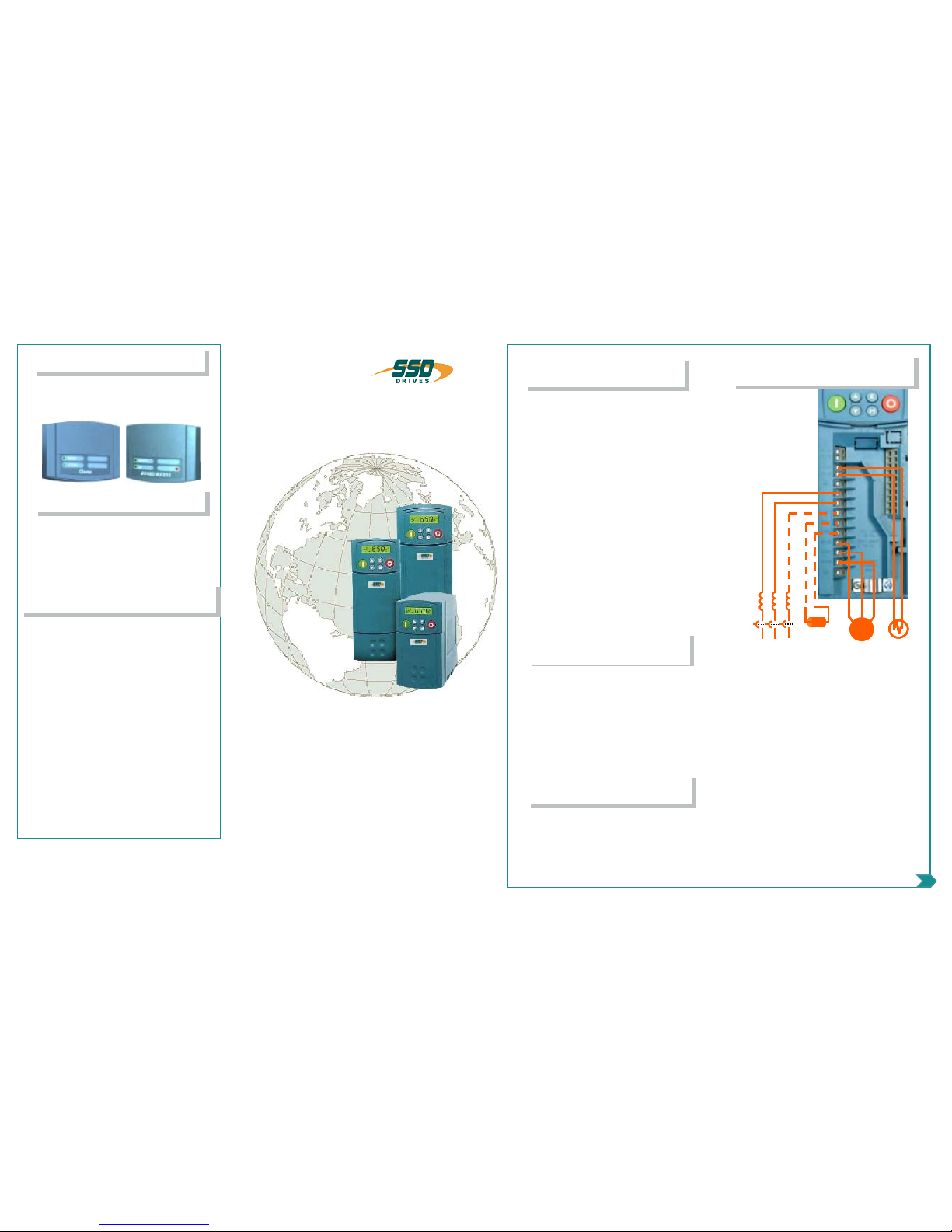
• Single-phase supply to L1, L2/N.
• 3-phase supply to L1, L2, L3.
• Motor connections to M1, M2, M3.
• Brake resistor between DC+, DBR
NOTE: Frame 1&2 230V units are not
fitted with a braking module. Do not use
a braking resistor on them.
• Motor thermistor to Th1A, Th1B.
Ground lugs are provided for each power
circuit. Follow proper grounding and shielding methods as described in the Instructio n
Manual.
If stop time is expected to be less than the
natural coasting time of the load, connect
the braking resistor across DC+ and DBR
(see Brake resistor note above)
The power terminals shown are for frame 2.
Although other frames may vary slightly in
appearance, their terminal designations and
Volts/Hertz mode (650 & 650V) – Basic
open loop operation, used in fans/pumps
and multi-motor applications.
Sensorless Vector mode (650V only) –
Tight speed regulation with good transient
torque capability, without the need for
speed feedback.
CONTROL MOD ES
FRAME RATIN G S
Frame 1 0.3 – 1 HP 230VAC 1 ph
0.25 – 0.75kW
Frame 2 1.5 – 2 HP 230VAC 1 ph
1.1 – 1.5kW
0.5 – 3 HP 460VAC 3 ph
0.37 – 2.2kW 400VAC
Frame 3 3 – 5 HP 230VAC 3 ph
2.2 – 4kW 400VAC
5 – 10 HP 460VAC 3 ph
3 - 7.5kW 400VAC
For larger sizes, see 650V Quickstart
650
650
series
series
Quick Start
Quick Start
POWE R CONNECTIONS
frames 1
frames 1--33
Volts/Hertz (model 650)
Inverters
Sensorless (model 650V)
*HA470679U100*
CLON ING
650 and 650V drives may be cloned using the
6514 Clone option that plugs into the keypad
slot. Settings include to/from, I/O configuration
and full/part transfer.
ADVANCED FEATURE S
The 650 has additional features which can be accessed via the drive menu, or for the 650V using
CE_Lite. Refer to the product manual for details.
Flycatching - When enabled, lets the drive start
into a spinning load by doing a frequency search.
Skip Frequencies – Two selectable avoidance frequencies and associated window for each.
PID – Provides closed loop process control
S-Ramp – When enabled, introduces a second
order slope to the ramp for smoother transitions.
Configurable Outputs – The digital outputs on the
650 can be configured to pick one of 6 parameters.
The outputs on the 650V are totally configurable.
Auto Restart - After a fault, the drive attempts a
number of restarts after a settable delay.
Custom Screens - Allows the use of a Custom parameter to be displayed. (650V only)
Encoder – Terminals 12 &13 (650V only) can be
used for a quadrature (not complementary) encoder
input for steady-state speed feedback.
thermistor
thermistor
braking
braking
resistor
resistor
~
~
motor
motor
AC Line Input
AC Line Input
thermistor
thermistor
braking
braking
resistor
resistor
~
~
motor
motor
AC Line Input
AC Line Input
AC Line Input
AC Line Input
Visit us at www.SSDdrives.com
USA: (704) 588-3246 UK: +44 (0)1903 737000
HA470679U100 Issue 2
Page 2
1111121213
13
P3
P3
1
1
2
2
3
3
4
4
5
5
6
6
7
7
8
8
9
9
10
10
START
START
REV DIR
REV DIR
JOG
JOG
SPEED
SPEED
REFERENCE
REFERENCE
+24VDC
+24VDC
HEALTH
HEALTH
N.O. CONTACT
N.O. CONTACT
CONFIGURATION PORT
CONFIGURATION PORT
650V only
650V only
EXTRA DIGITAL
EXTRA DIGITAL
INPUTS
INPUTS
650V only
650V only
1111121213
13
P3
P3
1111121213
13
P3
P3
1
1
2
2
3
3
4
4
5
5
6
6
7
7
8
8
9
9
10
10
START
START
REV DIR
REV DIR
JOG
JOG
SPEED
SPEED
REFERENCE
REFERENCE
+24VDC
+24VDC
HEALTH
HEALTH
N.O. CONTACT
N.O. CONTACT
CONFIGURATION PORT
CONFIGURATION PORT
650V only
650V only
EXTRA DIGITAL
EXTRA DIGITAL
INPUTS
INPUTS
650V only
650V only
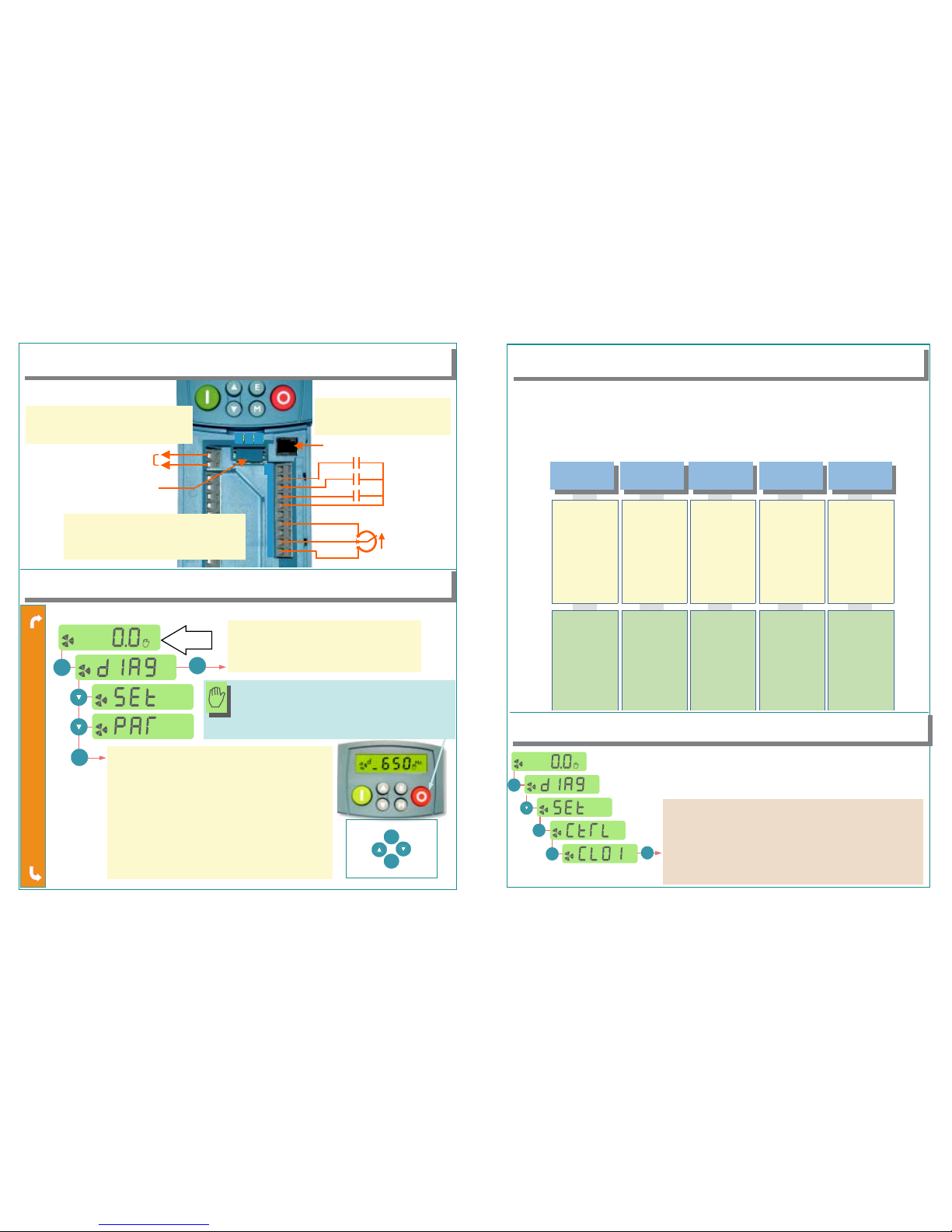
All calibration is done in software, through the keypad
APPLICATION MACROS
SETUP PARAMETERS
P1 Application Select Select the application macro
P2 Max Speed Set max speed in Hz
P3 Min Speed Set min speed in %
P4 Acceleration time Accel time to Max Speed in sec
P5 Deceleration time Decel time from Max Speed in sec
P6 Motor Current Motor full load current in amps
P7 Base Frequency Motor nameplate frequency in Hz
P8 Jog Setpoint Set jog speed in % of max speed
P9 Stop Mode 0=Ramp; 1=Coast; 2=Injection braking
P11 V/Hz shape 0=Linear; 1=Quadratic (fan or square)
P12 Overload Rating 0=150% for 30s.; 1=110% for 10s.
P13 Fixed Boost Set boost in % volts (V/Hz mode only)
P99 Password Set from 0001 to FFFF for protection
M
M
M
M
E
ESCAPE ONE LEVEL
ENTER MENU
SCROLL
UP
SCROLL
DOWN
DIAGNOSTICS
d1 Frequency Output frequency (Hz)
d2 Speed Setpoint Speed SP (% of Max Speed)
d3 DC Link Volts Voltage of DC Bus
d4 Motor Current Motor Current (amps)
After the first power-up, the 650 defaults to the most basic mode of operation, namely speed control. In addition, it has the
capability of being configured for special applications by loading the correct Application Macro.
Selecting an Application: Applications may be loaded during power-up by pressing and holding the STOP button, or by
setting P1 from the Parameters menu. 1=Speed Control; 2=Manual/Auto; 3=Preset Speeds; 4=Raise/Lower;
5=PI Control; 9=Custom (650Vonly)
Terminal Assigments: Different applications require different setup parameters, inputs and outputs. When an application
is selected, the 650 internally reassigns its control terminals for the relevant functionality. Also, depending on the application selected, an enhanced application-specific set of parameters will be visible, in addition to the regular parameters.
SPE EDCONTROL
P1=1
MANU AL/AUTO
P1=2
PRES ET SPEEDS
P1=3
RAI SE/LOWER
P1=4
PI CONTROL
P1=5
App-Specific Parameters
Control Terminal Assign
None
1 Common 0V
2 Speed In (V)
3 Speed In (mA)
4 +10V Supply
5 Speed Output
6 +24V Supply
7 Start button
8Fwd/Rev
9 Jog
10 Stop button
IP23 ANIN2 type
OP21 DIGIO2
OP31 Relay
1Common 0V
2 Manual Ref (V)
3 Auto Ref (mA)
4 +10V Supply
5 Speed Output
6 +24V Supply
7 Manual Start
8 Auto Start
9 Man/Auto
10 Fwd/Rev
IP301 Preset 1
IP302 Preset 2
IP303 Preset 3
IP304 Preset 4
IP305 Preset 5
IP306 Preset 6
IP307 Preset 7
IP308 Preset 8
1 Common 0V
2 Speed In (V)
3 Speed In (mA)
4 +10V Supply
5 Speed Output
6 +24V Supply
7Start
8 Preset Digital 1
9 Preset Digital 2
10 Preset Digital 3
P401 Ramp Time
P402 Max Value
P403 Min Value
P404 Reset Value
1 Common 0V
2Unused
3Unused
4 +10V Supply
5 Speed Output
6 +24V Supply
7Start
8 Raise Input
9 Lower Input
10 Ramp Reset
P501 Prop. Gain
P502 Integral Gain
1Common 0V
2 Reference (V)
3 Feedback (mA)
4 +10V Supply
5 Speed Output
6 +24V Supply
7 Start button
8Fwd/Rev
9Jog
10 Stop button
Power-up
screen
REFERENCE AND SEQUENCING
P
P
P
OWER
OWER
OWER
O
O
O
N
N
N
CALIBRATION
• Start contact between 6 and 7
• Jog contact between 6 and 9
• Reverse Direction contact between 6 and 8
• Speed potentiometer: 1 (Low), 4 (High),
2 (Wiper) OR
If using three wire control
• Start button (n.o.) between 6,7
• Stop button (n.c.) between 6,10
650V AND AUTOTUNE*
M
M
M
M
*for model 650V only. Autotune will not activate if in V/Hz mode.
CONTROL PARAMETERS
CL01 Control Mode 0 = V/Hz; 1 = Sensorless Vector (SV)
CL02 Nameplate RPM Enter RPM from motor nameplate
CL10 Motor Current Enter full load amps from motor nameplate
CL11 Motor Poles 2=3600rpm; 4=1800rpm; 6=1200rpm
CL12 Motor Voltage Enter motor nameplate voltage
CL20 Autotune Mode 0=stationary; 1=rotating (preferred)
CL21 Autotune Enable set to 1 and run the drive to autotune
CL81 Current Limit Current Limit setting as a % of CL10
For sensorless vector (SV) operation, an autotune is highly recommended,
preferably with the motor uncoupled and free to rotate. (if the motor cannot be
uncoupled, set CL20=0. See below).
SAVING
Changes
take effect
as soon as
they are
entered and
parameters
are saved
automatically
in a few
seconds
The drive powers up in LOCAL MODE. Use the green/
red buttons to start/stop and the up/down arrows to adjust
speed. To switch to REMOTE MODE, hold the STOP
button down until
L0C
disappears. To revert to LOCAL
MODE: At the
rdy
screen, push STOP until
L0C
appears.
 Loading...