

SSD COMPANY LIMITED 637f User Manual
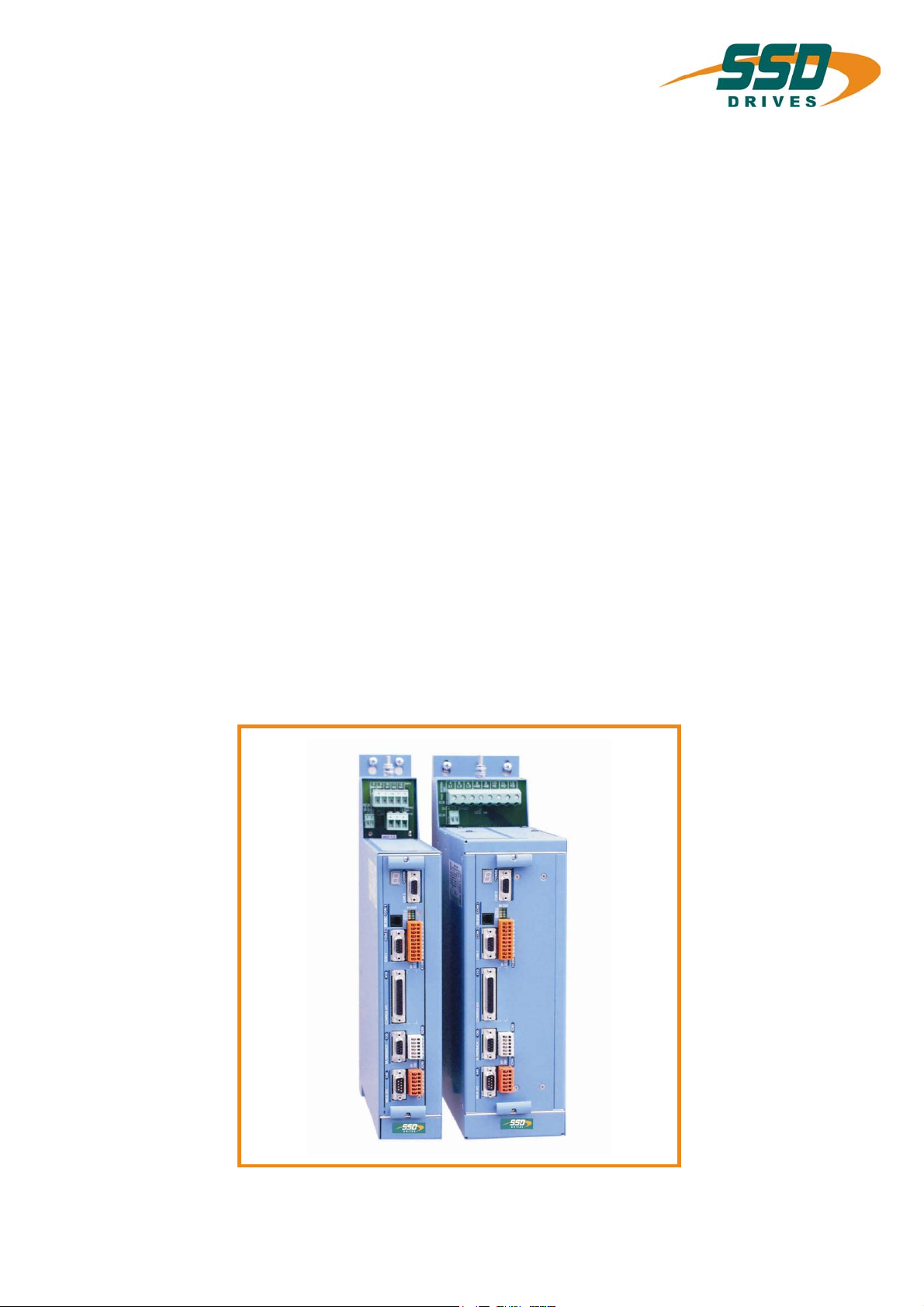
637f
Servo drive
Product
Manual
07-02-10-01-E-V0505.doc

UL:07-02-01
UL:07-02-02-01
UL: 07-02-09-02
UL:07-02-10-02
UL:07-05-02-03
Additional Supporting Documentation
Product Manual Rack 6 U and EMV
Product Manual Power Supply Plug-in Module NE B
Feedback System HIPERFACE
®
Product - Manual Safe Standstill SBT
Product Manual SUCOnet K
UL:07-05-03-02
UL:07-05-04-02
UL:07-05-05-02
UL:07-05-07-02
UL:07-05-08-02
Product Manual Bus Interface CAN for 635 / 637 / 637+ / 637f
Product Manual Bus Interface DP for 635 / 637 / 637+ / 637f
Product Manual Bus Interface Interbus S for 635 / 637 / 637+ / 637f
Product Manual I/O Interface for 635 / 637 / 637+ / 637f
Product Manual Bus Interface Device Net for 635 / 637 / 637+ / 637f
________________________________________________________________________________________________________________________________________________________________________________________________________________________
2 Product Manual Type: 637f 07-02-10-01-E-V0505.doc
UL:07-09-04-02
UL:10-06-03
UL: CD
UL:10-06-05
UL: 12-01
Additional Supporting Documentation
Product Manual Suppression Aids EH
Product Manual Serial Transfer Protocol
635 / 637 / 637+ / 637f EASY- Serial
EASYRIDER
Product Manual Software BIAS
Product Manual Accessories - Plugs
®
Windows - Software
®
UL:12-02
Product Manual Accessories - Cable
UL:12-03
Product Manual Ballast Resistors
©SSD Drives GmbH.
All rights reserved. No portion of this description may be produced or processed in any form without the
consent of the company.
Changes are subject to change without notice.
SSD Drives has registered in part trademark protection and legal protection of designs.
The handing over of the descriptions may not be construed as the transfer of any rights.
Made in Germany, 2005
________________________________________________________________________________________________________________________________________________________________________________________________________________________
07-02-10-01-E-V0505.doc Product Manaul Type: 637f 3

Seite
Table of Contents
The Most Important Thing First ........................................................................7
Safety Precation .................................................................................................8
1 General Information................................................................................10
1.1 System Description.......................................................................................................................10
1.1.1 Digital Communication..................................................................................................................11
1.1.2 Operation configurations...............................................................................................................11
1.1.3 Compatibility with 637 Servo Drives (Not required for new projects)...........................................12
1.1.4 Compatibility with 637+ Servo Drives..........................................................................................12
1.2 Type Code ...............................................................................Fehler! Textmarke nicht definiert.
1.2.1 Combination possibilities for the various communications / I/O - modules..................................14
1.2.2 Layout module slots......................................................................................................................15
1.2.3 Layout of Power Board.................................................................................................................15
1.3 Range Data...................................................................................................................................16
1.3.1 Insulation Concept........................................................................................................................16
1.3.2 General Data.................................................................................................................................16
1.3.3 Compact Units 637f/K D6R...........................................................................................................17
1.3.4 Plug-In Modules 637f/D6R............................................................................................................18
1.3.5 Single- and Three-Phase Supply..................................................................................................19
1.3.6 Output Power................................................................................................................................20
1.4 Dimensions...................................................................................................................................21
1.4.1 Dimensions for Compact Device and Plug-In Module..................................................................21
1.4.2 EMC-Clip (optional) .....................................................................................................................22
2 Connector Assignments and Functions ..............................................23
2.1 General View of Connections for Compact Device 637f/ K D6R 02 – 10 ....................................23
2.1.1 637f/K D6R 02...10 Width 14 HP..................................................................................................23
2.1.2 637f/K D6R 16...30 Width 20 HP..................................................................................................24
2.2 Connector Pin Assignments and Contact Functions....................................................................25
2.2.1 Power Connections for Plug-In Module 637f/D6R........................................................................25
2.3 Signal Connections.......................................................................................................................26
2.3.1 Control Signal Plug X10 - SUB D25 Socket.................................................................................26
2.4 Feedback Sensor X30..................................................................................................................29
2.4.1 Function module X300..................................................................................................................29
2.4.2 Feedback Sensor Connection X30 (SUB D 09 Socket)...............................................................30
2.5 Multi-function X40.........................................................................................................................31
2.5.1 Incremental Output.......................................................................................................................32
2.5.2 Incremental-Input..........................................................................................................................32
2.5.3 Stepper Motor Input......................................................................................................................33
2.5.4 Stepper Motor Input......................................................................................................................33
2.5.5 SSI Encoder Interface...................................................................................................................34
2.6 Digital Interfaces...........................................................................................................................35
2.6.1 Service Interface - COM1 (RS232)...............................................................................................35
2.6.2 Fieldbus Interface - COM2............................................................................................................36
2.7 Option module RP SBT ................................................................................................................44
2.7.1 Safe Stop......................................................................................................................................44
2.7.2 Brake control and PTC evaluation................................................................................................45
________________________________________________________________________________________________________________________________________________________________________________________________________________________
4 Product Manual Type: 637f 07-02-10-01-E-V0505.doc

Seite
Table of Contents
3 Operating modes....................................................................................46
3.1 Operating modes and pin functions..............................................................................................47
3.2 Configurable pin-functions (depending on the operating mode)..................................................48
3.3 Function diagrams from inputs and outputs .................................................................................49
4 Mechanical Installation ..........................................................................50
4.1 Mounting.......................................................................................................................................50
4.2 Control cabinet - mounting............................................................................................................50
4.3 Cooling..........................................................................................................................................50
5 Electrical Installation..............................................................................51
5.1 Safety............................................................................................................................................51
5.2 The danger of electric shocks.......................................................................................................51
5.3 Danger areas................................................................................................................................51
5.4 Grounding, safety grounding ........................................................................................................51
5.4.1 Ground connections......................................................................................................................51
5.5 Short-circuit capability and discharge currents.............................................................................51
5.6 Fuses, contactors, filters...............................................................................................................52
5.7 Correction of supply current .........................................................................................................53
5.8 Brake resistor................................................................................................................................54
5.8.1 Selection of the brake resistor......................................................................................................54
5.8.2 Configuration of the brake resistor ...............................................................................................55
6 Wiring instructions.................................................................................57
6.1 General Information......................................................................................................................57
6.2 Control cabling..............................................................................................................................57
6.3 Power cabling ...............................................................................................................................57
6.4 Installation of the rack...................................................................................................................57
6.5 Analog setpoint.............................................................................................................................57
6.6 Safety rules...................................................................................................................................57
6.7 Electromagnetic compatibility (EMC)............................................................................................57
6.7.1 Hints for mounting.........................................................................................................................58
6.7.2 Example for mounting...................................................................................................................59
6.7.3 Achieveable specifications and conditions...................................................................................59
7 Setting and programming......................................................................60
7.1 Jumper..........................................................................................................................................60
7.2 Digital communication see: Chapter 13........................................................................................60
8 Commissioning.......................................................................................61
8.1 Preparation ...................................................................................................................................61
8.2 Commissioning in steps................................................................................................................62
9 Diagnose und Fehlersuche....................................................................65
9.1 7-segment display.........................................................................................................................65
9.2 Reset of a regulator trouble..........................................................................................................69
9.3 Trouble shooting...........................................................................................................................70
10 Block circuit diagram.............................................................................71
________________________________________________________________________________________________________________________________________________________________________________________________________________________
07-02-10-01-E-V0505.doc Product Manaul Type: 637f 5

Seite
Table of Contents
11 General Technical Data..........................................................................72
11.1 Power circuit .................................................................................................................................72
11.2 Control circuit................................................................................................................................72
11.3 Signal inputs and outputs, connection X10 ..................................................................................72
11.4 Signal inputs and outputs, connection X120B resp. 120C...........................................................73
11.5 Digital control................................................................................................................................73
11.6 Digitale communication.................................................................................................................74
11.7 Resolver evaluation/transmitter principle......................................................................................74
11.8 Controllersystem...........................................................................................................................74
11.9 Analog-Outps................................................................................................................................75
11.10 Thermal data.................................................................................................................................75
11.11 Mechanical data............................................................................................................................75
12 Disposal...................................................................................................76
13 Software...................................................................................................77
13.1 EASYRIDER® Windows - Software..............................................................................................77
13.2 SSD Drives programming language BIAS....................................................................................78
14 Certificates..............................................................................................81
15 Index ........................................................................................................86
16 Modification Record...............................................................................88
________________________________________________________________________________________________________________________________________________________________________________________________________________________
6 Product Manual Type: 637f 07-02-10-01-E-V0505.doc

The Most Important Thing First
The Most Important Thing First
Thanks for your confidence choosing our product.
These operating instructions present themselves as an overview of the technical data and
features.
Please read the operating instructions before operating the product .
If you have any questions, please contact your nearest SSD Drives representative.
Improper application of the product in combination with dangerous voltage can lead to
injuries.
In addition, damage can also occur to motors or other products.
Therefore please observe our safety precautions strictly.
Safety precautions
We assume that, as an expert, you are familiar with the relevant safety regulations,
especially in accordance with VDE 0100, VDE 0113,VDE 0160, EN 50178, the accident
prevention regulations of the employers liability insurance company and the DIN
regulations and that you are able to use and apply them.
As well, relevant European Directives must be observed.
Depending on the kind of application, additional regulations e.g. UL, DIN are subject to be
observed.
If our products are operated in connection with components from other manufacturers,
their operating instructions are also subject to be observed strictly.
________________________________________________________________________________________________________________________________________________________________________________________________________________________
07-02-10-01-E-V0505.doc Product Manaul Type: 637f 7

Safety Precation
Attention
Digital servo drives, corresponding to EN 50178/VDE 0160, are power
electronic components utilized for the regulation of the flow of energy in
electrical power installations. They are exclusively designed and configured to
supply SSD Drives, or SSD Drives approved, servo motors. Handling,
installation, operation, and maintenance are only permitted under the conditions
of and in keeping with the effective and/or legal regulations, regulation
publications and this technical document.
Safety Precautions
The operator must make sure that these regulations are strictly followed.
The Concept of Galvanic Separation and Insulation:
Galvanic separation and insulation corresponding to EN 50178/VDE 0160,
provides for additional insulation protection.
In addition, all digital signal inputs and outputs are provided with a galvanic
separation utilizing either a relay or an optical coupler. In this way, an increased
level of protection against potential interference and a limitation of potential
damage due to incorrect connections are provided.
The voltage level must not exceed the designated low safety voltage of 60V
DC or 25V AC, respectively, in accordance with EN 50178/VDE 0160.
The operator must make sure that these regulations are strictly followed.
High Voltage!
Danger of Electrocution!
Life Threatening Danger!
Danger !
Caution !
Due to safety considerations and the product guarantee, the
operator is prohibited from opening the servo drive case. Service,
maintenance and repair of SSD Drives products should only be
carried out by specified representatives of the company. Expert
configuration and professional installation, as described by this
document, are the best way to insure for the problem-free operation
of the SSD Drives servo drive!
________________________________________________________________________________________________________________________________________________________________________________________________________________________
8 Product Manual Type: 637f 07-02-10-01-E-V0505.doc

Please
observe!
Safety Precautions
Pay Special Attention to the Following:
Permissible Protection Class: Protective Grounding - operation is only permitted
when the protective conductor is connected according to regulations.
The operation of servo drives is not allowed, under the sole use of a residual
current operated protective device as protection against indirect touching. The
servo drive may only be used in the rack or in its compact enclosure.
Furthermore the regulator is designed solely for control cabinet operation.
Work on or with the servo drive may only be carried out with insulated tools.
Installation work may only be done in a de-energized state. When working on
the drive, one should not only block the active – input, but also separate the
drive completely from the main power connection.
CAUTION - Risk of Electrical Shock:
Wait 3 minutes after switching the component off, to allow the capacitors to
discharge.
Screws sealed with varnish fulfill an important protection function and may not
be moved or removed.
It is prohibited to penetrate the inside of the unit with objects of any kind.
Protect the unit from falling parts, pieces of wire, metal parts, etc., during
installation or other work in the control cabinet. Metal parts can lead to
a short-circuit in the servo drive.
Before putting the unit into operation, remove additional covers so that the unit
does not overheat. With measurements at the servo drive it is absolutely
necessary to observe the potential separation
SSD Drives GmbH is not liable for damages which may occur when the
instructions and/or the applicable regulations are not explicitly observed!
Stop !
________________________________________________________________________________________________________________________________________________________________________________________________________________________
07-02-10-01-E-V0505.doc Product Manaul Type: 637f 9
1 General Information
1 General Information
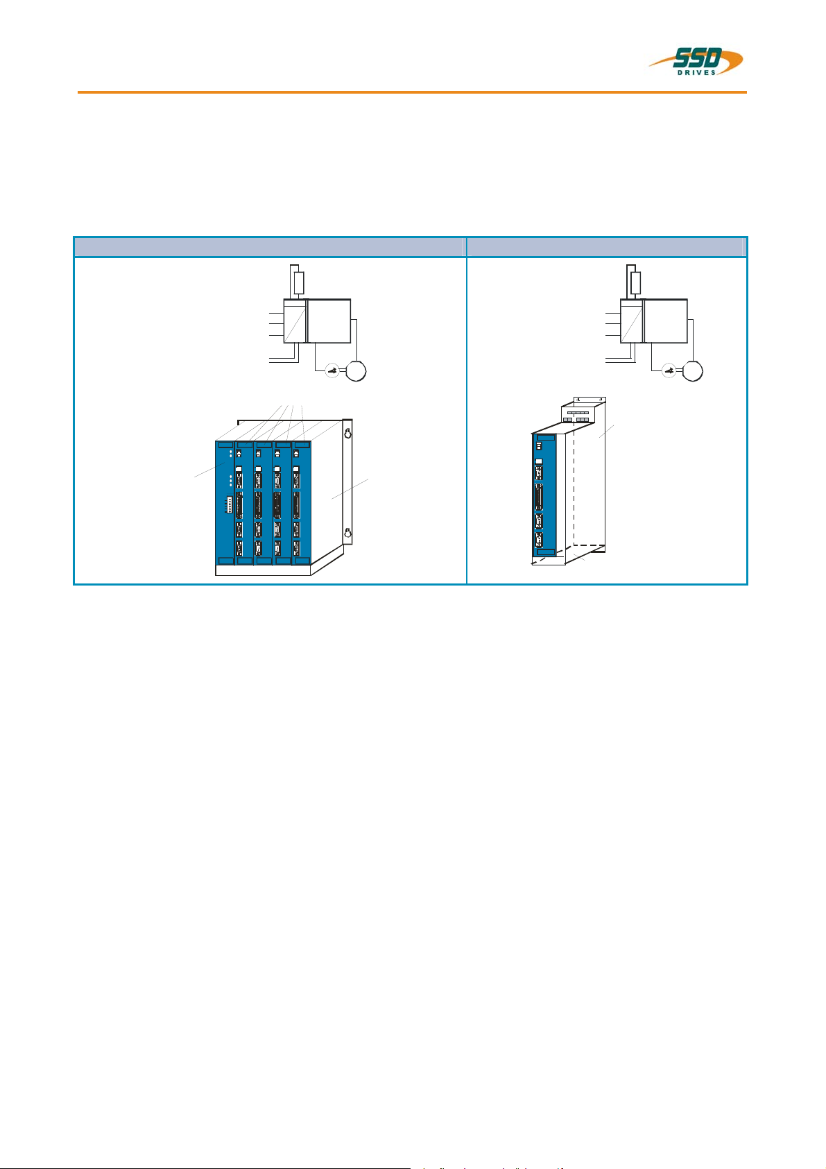
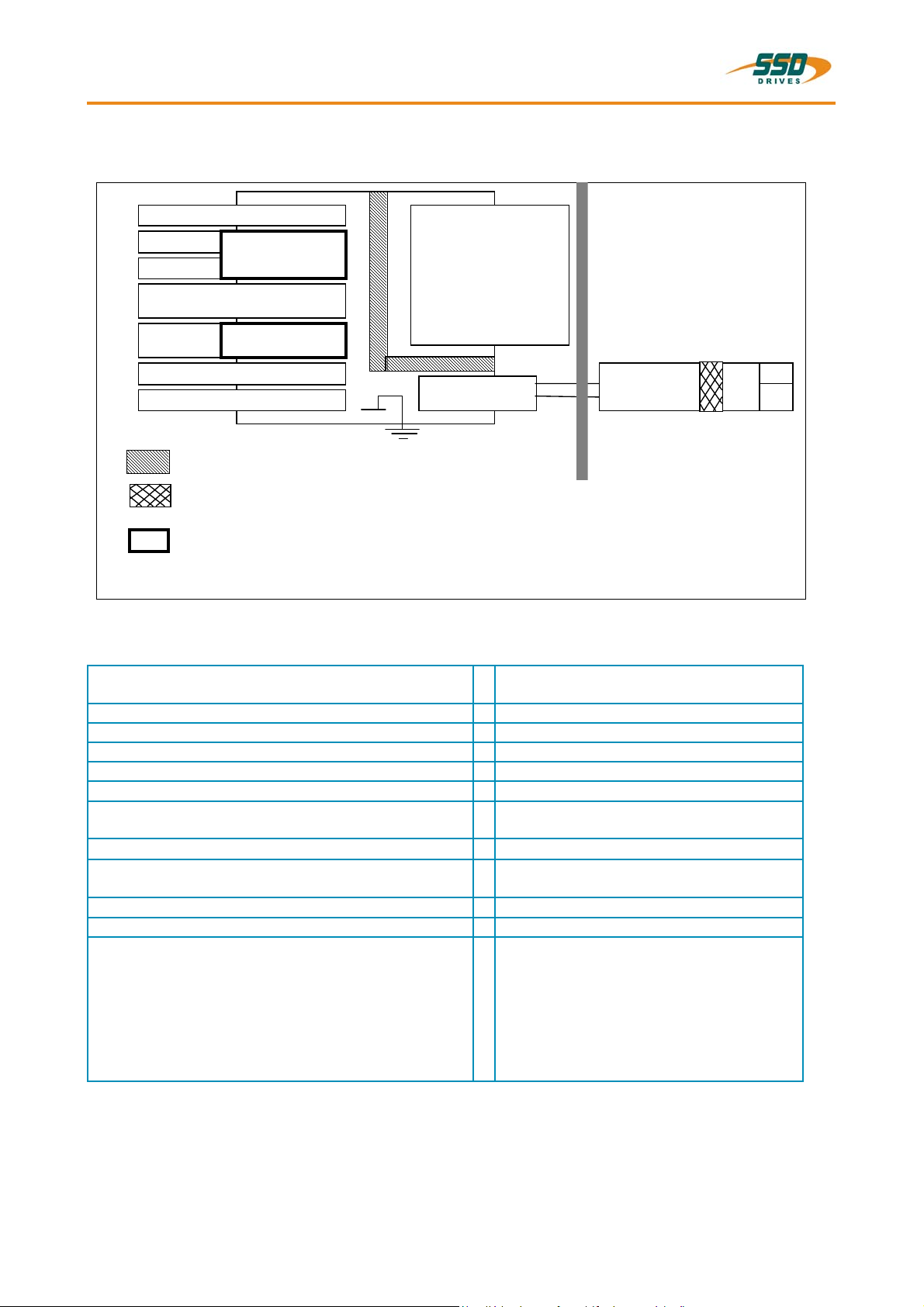
1.1 System Description
The 5th generation of the digital servo drive serves to regulate the current, speed and position of
AC servo motors, (standard: with resolver)
All control circuits and functions are realized digitally.
System variants
Rack - version: 637f/D6R.... Compact - version: 637f/K D6R....
Su pply volta ge:
1*oder 3* 230VAC/50..60Hz
3*40 0...460VA C/50..60Hz
Power supp ly
p lug -i n modul e
NE B
R
Us 24VDC
Fan
AC
DC
Servodrives
637f/ K D6 R
M
Rack, R6
R6 EMV
Su pply volta ge:
1*oder 3* 230VAC/50..60Hz
3*40 0...460VA C/50..60Hz
or
Us 24VDC
Servodrive
Fan
R
637f/ K D6 R
AC
DC
Power supply unit
Explanations for the rack and power supply modules are documented in separate descriptions.
If required, the returned braking energy can be drawn off into additional external ballast resistors.
The AC-supply voltage is fed directly or via transformer to the associated power supply module.
The devices are designed to be operated on networks which are grounded at the
centre point (TN networks) !
M
________________________________________________________________________________________________________________________________________________________________________________________________________________________
10 Product Manual Type: 637f 07-02-10-01-E-V0505.doc
General Information 1
System Description
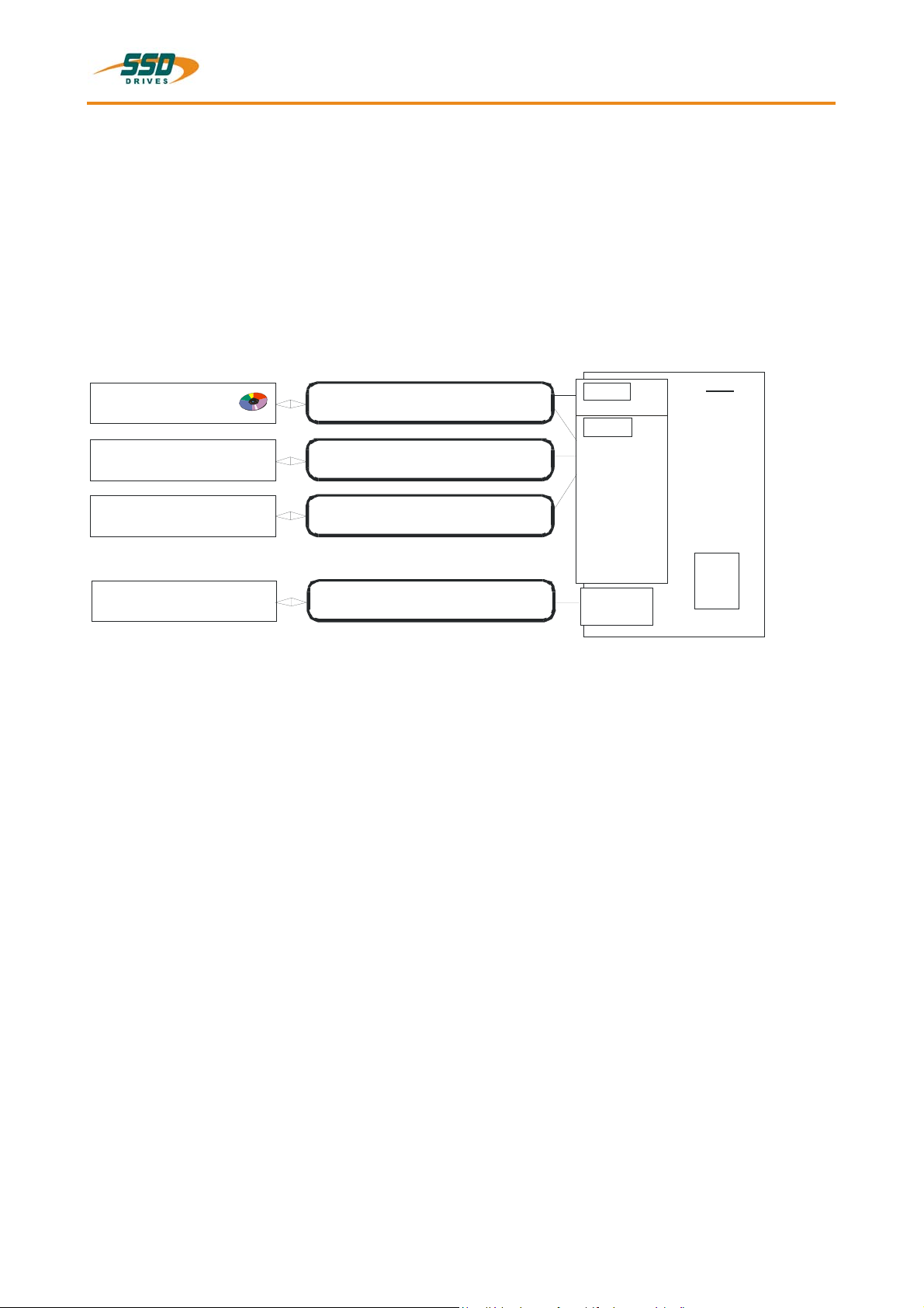
1.1.1 Digital Communication
Diagnostics / Setup
General: by 7 segment display
Comfortable: via PC with EASYRIDER
(serial interface RS232)
Communication
The serial-communication-protocol is open and fully documented.
(Explanation see separate documentation)
Every user has unrestricted access to all functions and parameters.
EASYRIDER
customer-ma de software
PLC Software
PLC, binary selectionl,+/- 10V
®
Windows – Software from version V8.xx
⌧
⌧
⌧
COM1
RS232
COM2
X10
RS232
RS422
RS485
CAN-BUS 1
CAN-BUS 2
SUCOnet K
Profibus DP
Interbus S
Devi ceNet
current-loop
position-loop
637f
speed-loop
PLC
instr uctions
1.1.2 Operation configurations
There are opportunities ranging from simple current and speed control to programmable position control
processes (PLC), supported by the 1500 BIAS command blocks.
"BIAS" User shell for intelligent drive controls
see:
chapter 3 Operating modes
chapter 13.2 BIAS commands
chapter 13.3 Extended BIAS commands
diagnostic s
setup
⌧
programming
________________________________________________________________________________________________________________________________________________________________________________________________________________________
07-02-10-01-E-V0505.doc Product Manaul Type: 637f 11
1 General Information
System Description
1.1.3 Compatibility with 637 Servo Drives (Not required for new projects)
The 637f series servo drives are essentially pin- and functionally compatible with the servo drives 637.
However, when a servo drive 637 is replaced with a 637f drive, the existing application must be checked and
carefully tested to determine compliance under the corresponding safety precautions.
The following points should be checked in any case and eventually be adjusted before the function test:
1. Motor direction parameter and limit switch setting (see release note V6.12)
2. Position setpoints and comparison values have to be quadrupled, resp. sixteenfold
(low encoder resolution at 637)
3. Coupling factors in synchronous applications have to be quadrupled, resp. sixteenfold
(low encoder resolution at 637)
4. Execution of BIAS- and PLC programs is 2.25 times quicker than with the 637. This can cause timing
problems with improper programming (e.g. wait times with NOPs)
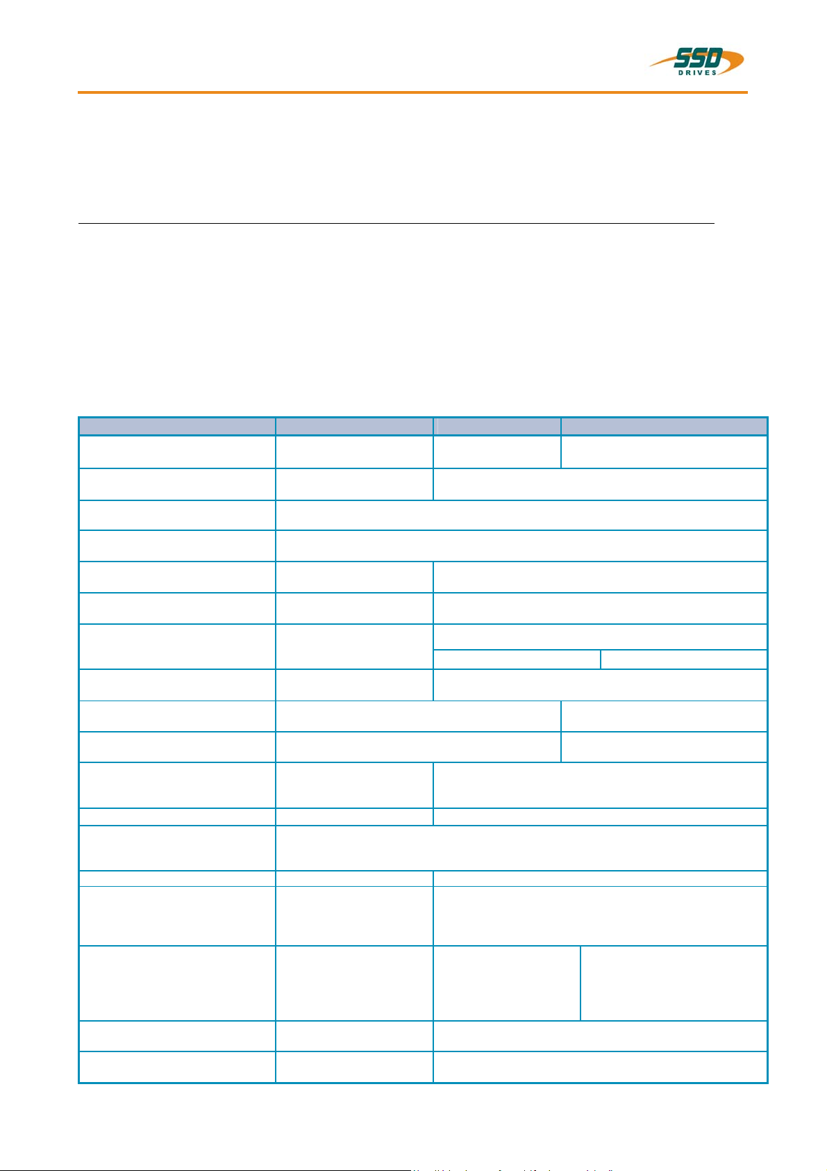
1.1.4 Compatibility with 637+ Servo Drives
(Not required for new projects)
Der Servoregler 637f ist voll funktionskompatibel zu 637+
Funktion 637 637+ 637f
PC-Operating-Software
PC-Connection-Cable
see: chapter 2.6.2.3
Power Part, Power Data and
Power Connectors
Control Singals, Connector X10
see: chapter 2.3.2
Analog Set Point X10.5/18,
Resolution
Resolver Signals, Connector X30
see: chapter 2.4.2
Feedback – Interface - Module
X300
see: chapter 2.4.1
Multifunction, Connector X40
see: chapter 2.5
Interface, Connector COM2
see: chapter 2.6.2 – 2.6.2.9
Options Module
see: chapter 2.6.2 – 2.6.2.10
Operating Modes, BIAS –
Functions
see: chapter 3 and 13.2
PROG-Key present
Analog-Output - Test Signals
MP1/MP2:
> connector X 10
> Front Test Sockets yes no
Technical Data
Analog Out
MP1 / X10.17
MP2 / X10.6
Control Loops
see: chapter 11.5
Control Loop Parameters
Jumper
see: chapter 7.1
EASYRIDER
or Windows Version
PC - SUBD-9 to
LEMO connector (COM1)
12/14 Bit Resolution
command set compatible
12/14 bits ≈ 1revolution
7 bits , Rout = 10 kOhm
7 bits , Rout = 10 kOhm
®
DOS Version
12 bits
pin–compatible
-
compatible
position value
Generally compatible,
EASYRIDER®
Windows Version
equal pinning and function
equal
equal
X 10.6 / X 10.17
performance boost
compared
cycle time twice as fast
EASYRIDER®
Windows Version V8.xx
PC - SUBD-9 to
4-pin module connector (COM1)
equal
14 bits
extended functionality
16 Bit Resolution
HIPERFACE
- SIN / COS
extended functionality
extended functionality
CAN BUS 2, RP_2Cx
extended functionality
RP_SBT
future extensions possible
position value 16 bit ≈ 1 revolution
not available
8 bits , Rout = 1.8 kOhm
10 bits , Rout = 1.8 kOhm
to 637:
possible optimization required
JP2.2, JP2.3, JP2.7, JP2.8
performance boost
compared to 637f:
cycle time for speed twice as
fast,
position eight times as fast
as
________________________________________________________________________________________________________________________________________________________________________________________________________________________
12 Product Manual Type: 637f 07-02-10-01-E-V0505.doc
General Information 1
1.2 Modle code
standard optional special
marking
type: 637f/
a
X D6R XX .S5 -X -X -XXX -XXX -XXx -XXX
marking description
a
b
c
d .S5 = Digital servo drive 5th generation
e
f
g1
g2
h
i
at assignment [C] Interface you can used 1 x CAN *
XXXX/ = 637f ≅ SSD Drives-fast-design
K = 1-axis-compact digital-servo drive system
0 = design plug-in device
D6R = Digital 6U drive
Rated current:
02 = 2 amps
04 = 4 amps
06 = 6 amps
10 = 10 amps
16 = 16 amps
22 = 22 amps
30 = 30 amps
Intermediate circuit rated voltage:
-3 = 325V (230V AC) 16..30A only as rack system possible
-7 = 650V (460V AC)
-E = With EMC-Clip unit
-0 = Without EMC-Clip unit
additional option modules on the drive for communication via COM2
-000 = None option
-232 = RS 232 interface ≅ slot A (B)
-422 = RS 422 interface ≅ slot A (B)
-485 = RS 485 interface ≅ slot A (B)
-CAN = CAN – Bus ≅ slot A (B)
-2CA = 2 x CAN (without I/O’s) ≅ slot B (A) / [C*]
-2C8 = 2 x CAN + 4 outputs and 4 inputs ≅ slot B (A) / [C*]
-DEV = CAN - Bus / DeviceNet ≅ slot B (A)
-SUC = SUCOnet K ≅ slot B (A)
-PDP = Profibus DP ≅ slot B (A)
-IBS = Interbus S (Attention: changed front plate) ≅ slot B (A)
-EA5 = I/O interface (5 inputs, 2 outputs) ≅ slot B (A)
additional option modules on the drive via X200
-000 = No Options
-EAE = I/O interface (14 inputs, 10 outputs) ≅ slot C
-SBT = Safety – Board Module ≅ slot C
X300 – Function module
-RD2 = Standard X30
-HF2 = HIPERFACE module 2nd version ≅ slot D
-SC2 = Sinus / Cosinus - module 2nd version ≅ slot D
Entry only at use
-Sxx = Special - resistance - setting
-X7x = Broad-band contact X10.7 - X10.8
-BSx = Protection moisture condensation
-B7x = Protection moisture condensation + Broad-band contact X10.7 - X10.8
-923 = Jumper 209 / 2 - 3 open , by SBT - Option Thermo - Contact X30 (PTC / NTC)
Typical Example
A typical example of an order of a 1-axis compact device in SSD Drives design:
Type:
a b c d e f g1 g2 h i
637f/ KD6R 02 .S5 -3 -0 -2CA -EAE -RD2 -
b c d e f g1 g2 h i
(Attention: changed front plate)
Resolver module 2nd version ≅ slot D
________________________________________________________________________________________________________________________________________________________________________________________________________________________
07-02-10-01-E-V0505.doc Product Manaul Type: 637f 13
1 General Information
x
x
Modle Code
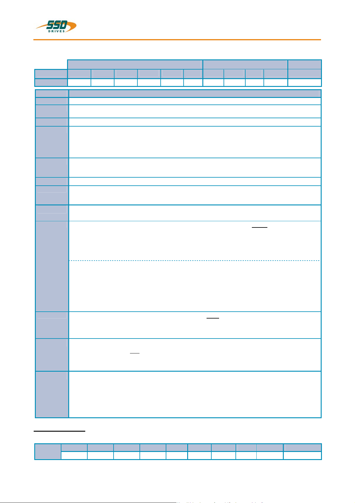
1.2.1 Combination possibilities for the various communications / I/O - modules
Slots A B C
Option modules 232 422 485 CAN 2CA 2C8 DEV SUC PDP IBS EA5 EAE SBT *2CA *2C8
Type Codel
637f/xD6Rxx.S5-x-x-232-000-xxx
637f/xD6Rxx.S5-x-x-232-EAE-xxx
637f/xD6Rxx.S5-x-x-232-SBT-xxx
637f/xD6Rxx.S5-x-x-232-2CA-xxx
637f/xD6Rxx.S5-x-x-232-2C8-xxx
637f/xD6Rxx.S5-x-x-422-000-xxx
637f/xD6Rxx.S5-x-x-422-EAE-xxx
637f/xD6Rxx.S5-x-x-422-SBT-xxx
637f/xD6Rxx.S5-x-x-422-2CA-xxx
637f/xD6Rxx.S5-x-x-422-2C8-xxx
637f/xD6Rxx.S5-x-x-485-000-xxx
637f/xD6Rxx.S5-x-x-485-EAE-xxx
637f/xD6Rxx.S5-x-x-485-SBT-xxx
637f/xD6Rxx.S5-x-x-485-2CA-xxx
637f/xD6Rxx.S5-x-x-485-2C8-xxx
637f/xD6Rxx.S5-x-x-CAN-000-xxx
637f/xD6Rxx.S5-x-x-CAN-EAE-
xxx
637f/xD6Rxx.S5-x-x-CAN-SBT-xx
637f/xD6Rxx.S5-x-x-2CA-000-xxx
637f/xD6Rxx.S5-x-x-2CA-EAE-xxx
637f/xD6Rxx.S5-x-x-2CA-SBT-xxx
637f/xD6Rxx.S5-x-x-2C8-000-xxx
637f/xD6Rxx.S5-x-x-2C8-EAE-xxx
637f/xD6Rxx.S5-x-x-2C8-SBT-xxx
637f/xD6Rxx.S5-x-x-DEV-000-xxx
637f/xD6Rxx.S5-x-x-DEV-EAE-xxx
637f/xD6Rxx.S5-x-x-DEV-SBT-xxx
637f/xD6Rxx.S5-x-x-SUC-000-xxx
637f/xD6Rxx.S5-x-x-SUC-EAE-xx
637f/xD6Rxx.S5-x-x-SUC-SBT-xxx
637f/xD6Rxx.S5-x-x-PDP-000-xxx
637f/xD6Rxx.S5-x-x-PDP-EAE-xxx
637f/xD6Rxx.S5-x-x-PDP-SBT-xxx
637f/xD6Rxx.S5-x-x-PDP-2CA-xxx
637f/xD6Rxx.S5-x-x-PDP-2C8-xxx
637f/xD6Rxx.S5-x-x-IBS-000-xxx
637f/xD6Rxx.S5-x-x-IBS-EAE-xxx
637f/xD6Rxx.S5-x-x-IBS-SBT-xxx
637f/xD6Rxx.S5-x-x-EA5-000-xxx
637f/xD6Rxx.S5-x-x-EA5-EAE-xxx
637f/xD6Rxx.S5-x-x-EA5-SBT-xxx
637f/xD6Rxx.S5-x-x-000-EAE-xxx
637f/xD6Rxx.S5-x-x-000-SBT-xxx
-000 = none option possible com bination at assignment [C] Interface you can used 1 x CAN *
-
-
-
-
-
- -
- -
- -
- -
- -
- - -
- - -
- - -
- - - -
- - - -
- - - -
- - - - -
- - - - -
- - - - -
- - - - -
- - - - -
- - - - -
- - - - -
- - - - -
- - - - -
- - - - -
- - - - -
- - - - -
- - - - -
- - - - -
- - - - -
- - - - -
- - - - -
- - - - -
- - - - -
- - - - -
- - - - -
- - - - -
Example:
637f/xD6Rxx.S5-x-x-232-EAE-RD2
… -232 = on slot A
… -EAE = on slot C
… -RD2 = on slot D (Motor - Feedbacksystem)
- - - - - - - - - - - - - -
- - - -
- - - -
- - - -
- - - -
- - -
- - -
- - -
- - -
- - -
- -
- -
- -
- -
- -
-
- - - - -
-
- - - - - -
-
- - - - - - -
-
- - - - - - - -
-
- - - - - - - - -
-
- - - - -
-
- - - - - -
-
- - - - - - -
-
- - - - - - - -
-
- - - - - - - - -
-
- - - - -
-
- - - - - -
-
- - - - - - -
-
- - - - - - - -
-
-
-
-
- - - - - - - - -
-
- - - - -
-
- - - - - -
-
- - - - - - - - -
-
- - - - -
-
- - - - - -
- - - - - - - - -
- - - - -
- - - - - -
-
- - - - - - - -
-
- - - -
-
- - - - -
-
-
-
-
-
-
-
-
-
-
-
-
-
-
-
-
-
-
-
- -
- -
- -
- -
- -
- - -
- - -
- - -
- - - -
- - - -
- - - -
- - - - -
- - - - - -
- - - - - - -
- - -
- - - -
- - - - - -
- -
- - -
- - - -
- - - - -
- - -
- -
- - -
- -
- - -
- -
- - -
- -
- -
- -
- - -
- -
- - -
- -
- - -
- -
- - -
- -
- - - -
-
- -
- - -
- -
- - - -
- - -
-
- -
- - -
- -
-
-
-
-
________________________________________________________________________________________________________________________________________________________________________________________________________________________
14 Product Manual Type: 637f 07-02-10-01-E-V0505.doc
General Information 1
Modle Code
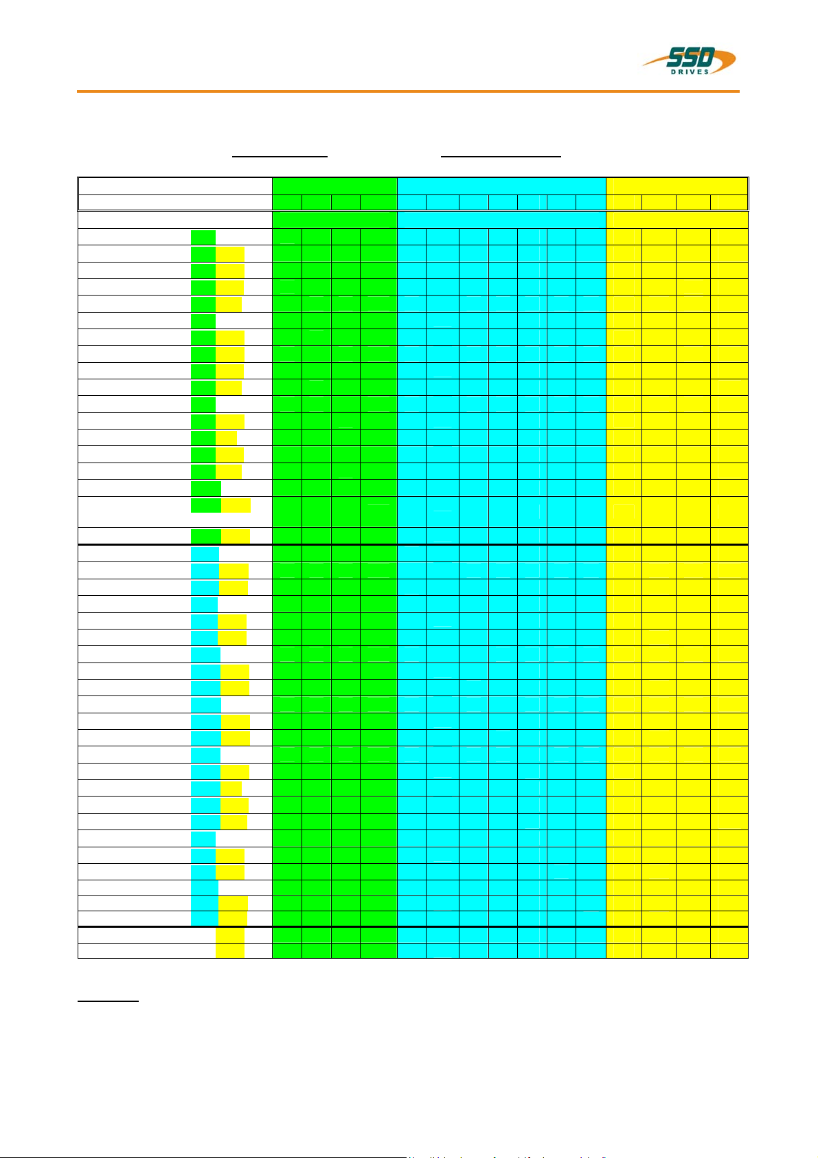
1.2.2 Layout module slots
Module slots:
A -232
-422
-485
-CAN
B -2CA
-2C8
-DEV
-SUC
-PDP
-IBS
-EA5
C -EAE
-SBT
*-2CA
*-2C8
Motor - Feedbacksysteme:
-RD2: Standard resolver
D -HF2: Option HIPERFACE
* kann nur 1 mal CAN verwendet werden
Note: The option modules of the slots A / B / C can only be reached after removing the cooling plate.
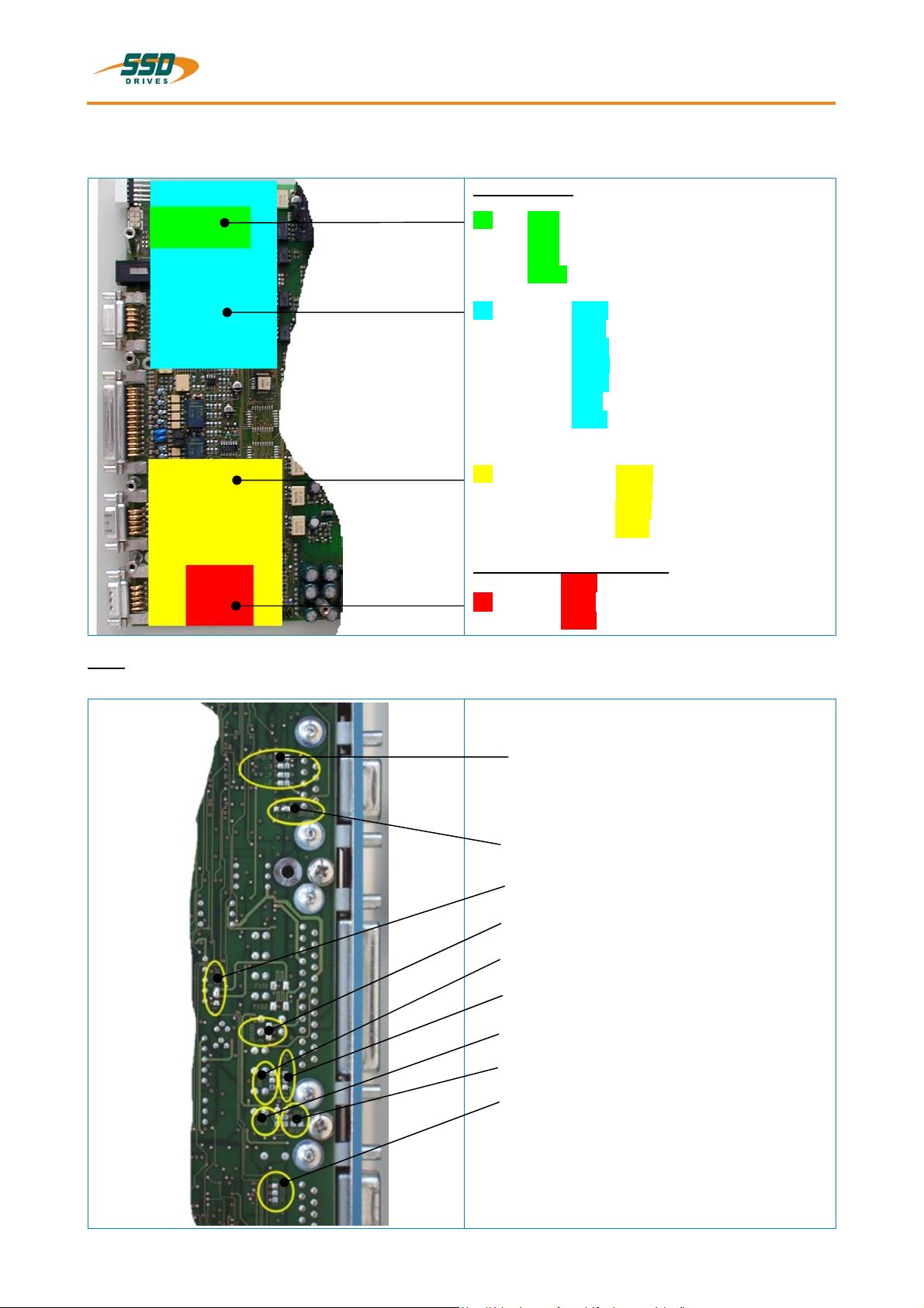
1.2.3 Layout of Power Board
View solder side (solder jumper)
JP2.8
JP2.3
JP2.7
JP2.2
JP101. 1/ 2/ 3
JP102 1/ 3/ 2
JP100 2/ 3/ 1
JP1 1/ 3/ 2
JP2 2/ 3/ 1
JP3 1/ 3/ 2
JP4 2/ 3/ 1
JP209. 1/ 2/ 3
Solder jumper function
see: Chapter 7.1
®
-SC2: Option rotor position transmitter
________________________________________________________________________________________________________________________________________________________________________________________________________________________
07-02-10-01-E-V0505.doc Product Manaul Type: 637f 15
1 General Information
1.3 Range Data
1.3.1 Insulation Concept
COM1
COM2
Remote IN
X10
analog
X10
digital
X30
X40
1)
dep. Optionsmodule
1)
GND
doubl e insulation VDE 0160
Insul ation of cont rol voltage supply
Tak e Car e ! The insulat ion of control ( Com1..X40) depends on the insulation of control voltage suppl y
Required for safe separation (P E LV): d ouble insulation
Additional in su lation via opto-coup ler o r r elay (wit hout Safet y-Func tions)
see addit i onal hint s, c hapter 2.4. 2
power - terminal s
L1, L2, L3
DC-bus
M1, M2, M3
brak - ci r quit
Us DC 24 V
PE
custome r pa rt
power supply
DC 24 V
AC
1.3.2 General Data
Enclosure Rating for Mounting in a Cubicle
Operating Temperature Range EN 50178 / VDE 0160, class 3K3
Storage Temperature Range -25°...+55° C
Air Pressure 86 kPa - 106 kPa
Humidity 5% - 85%, 40°C
Operating Temp 0...40°C
Reduced Operation
De-rating of the Output Current
Altitude h
Reduced Operation
De-rating of the Output Current
Safety Over Voltage - Category of Power Circuit EN 50178 / VDE 0160, UL, cUL III,
Pollution Degree - for Mounting in a Cubicle VDE / UL: 2
Vibration Test in Accordance with
DIN IEC 68-2-6, Test FC
Condition for Testing
Frequency Range
Amplitude
Acceleration
Test Time per Axis
Frequency Sweep Speed
IP20
1)
>40°...< 50°C
2% /°C
1)
h ≤ 1000m
h > 1000...≤ 4000m
1% / 100m
10...57Hz 57...150Hz
0,075 mm
1g
10 sweep cycle
1 octave/min
1)
Use only fan-cooled devices. For reduced operating
conditions, no UL approval is available.
L1
N
________________________________________________________________________________________________________________________________________________________________________________________________________________________
16 Product Manual Type: 637f 07-02-10-01-E-V0505.doc
General Information 1
Range Data
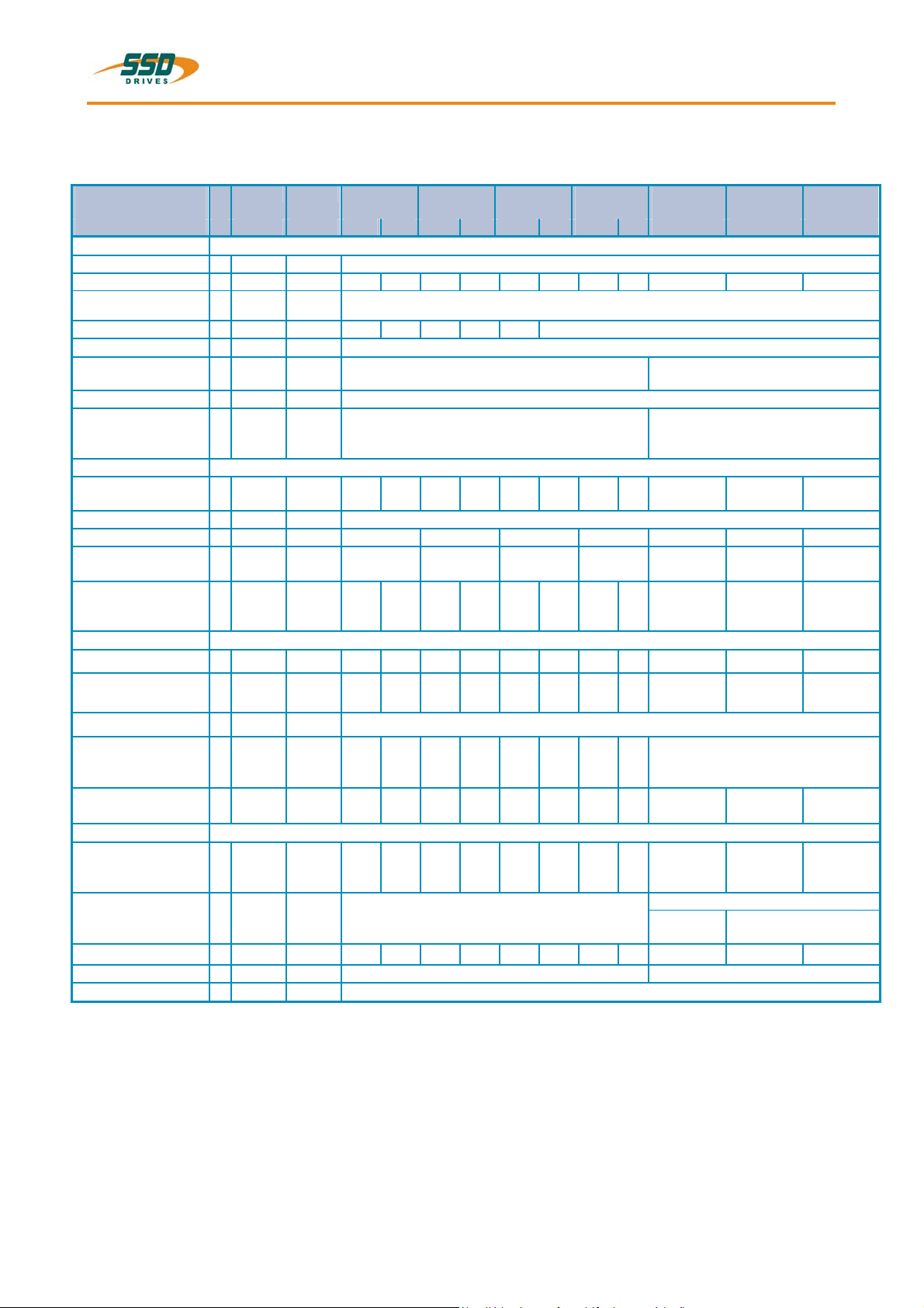
1.3.3 Compact Units 637f/K D6R
Compact Units
-3 -7 -3 -7 -3 -7 -3 -7 -7 -7 -7
Input
Supply Voltage
50..60 Hz
Phases
Supply Peparation
Power-On Current
Limit
Control Voltage
Control Current
incl. Fan
Output
Sine-Wave Voltage
at Un
De-rating of Unr
Rated Current RMS
Max. Current RMS
Time for Imax
Min. Motor
Inductance
(terminal / terminal)
Brake Circuit
Setpoint DC
Max. Power
min. [V] 14
Un [V] 230 460 230 460 230 460 230 460 460 460 460
max.
1;3 3 1;3 3 1;3 3
Fuses, contacts, filters see chapter 5.6
model
1)
Us [V] 21,5....24....29, attention: insulation-concept chapter 1.3.1
Is
DC
Unr [Veff] 220 447 220 447 220 447 220 447 447 447 447 3)
Inr [A] 2 4 6 10 16 22 30
Imaxr
4)
min.
Lph/ph [mH] 6,0 12,0 3,0 6,0 2,0 4,0 1,2 2,4 2,0 1,1 0,8
Ub [V] 375 730 375 730 375 730 375 730 730 730 730
637f / K D6R 02
.S5
toleranc
e
K D6R 04
.S5
K D6R 06
.S5
K D6R 10
.S5
+ 10%
NTC 4 Ohm NTC 2 Ohm
[A] Continuous: max. 1,2A Power-On-Peak:
nom. 3A; max.. 6A / 0,8 mS, 2,5A / 25 mS
depending upon load and single or 3-phase supply. (see chapter 1.3.5)
[A]
Sec
4
5
8
5
12
5
20
5
K D6R 16
.S5
K D6R 22
.S5
K D6R 30
Continuous: max 1,5A PowerOn-Peak: nom. 3A;
max. 6A / 0,8 mS, 3A / 25 mS
32
5
44
5
.S5
60
5
Pbmax [kW] 4,5 8,7 4,5 8,7 6,7 13,0 11,2 21,7 29,0 34,8 34,8
3)
Continuous Power
Internal Resistor
Min. External
Resistor
General
Power Loss
Fan, Electronic
24V DC
Pbnenn [W]
2)
Rbint
Pd
Pmax
Rbextmi
n
[Ω]
[W]
[kW]
[Ω]
PE loss
[W]
[V]
≤ 560
100
30
1,4
30
1,7
30
1,4
30
1,7
30
1,4
30
1,7
30
1,4
30
1,7
------
300
100
300
100
300
100
300
47 82 47 82 27 47 15 27 20 15 15
29
29
29
29
29
29
29
29
2 Piece L 024 / (12TE * 25)
1 Piece L 024 / (12TE * 15)
36
2 Piece L 024 / (16TE x 25) Fan Models
1 2 Piece L 024 /
36
(16TE x 20)
Power Stage per A
[W/A] 9 12 9 12 9 12 9 12 12 12 12
Weight [kg] 5,0 8,8
Additional Data
see: chapter 11
1) Suggested: transformer-based supply
2) Use only SSD Drives-released types
3) Max. continuous performance reduced to 80%, see chapter 1.3.6
4) References chapter 1.3.6
36
________________________________________________________________________________________________________________________________________________________________________________________________________________________
07-02-10-01-E-V0505.doc Product Manaul Type: 637f 17
1 General Information
t
Range Data
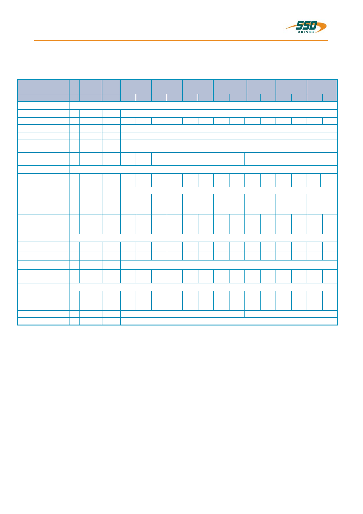
1.3.4 Plug-In Modules 637f/D6R
Plug-In Modules
-3 -7 -3 -7 -3 -7 -3 -7 -3 -7 -3 -7 -3 -7
Input
DC-BUS Rated min. [V] 20
Ug [V] 325 650 325 650 325 650 325 650 325 650 325 650 325 650
max.
Control Voltage Us [V] 24V DC +20% -10%, attention: insulation-concept chapter 1.3.1
Control Current
Fan
Output
Sine-Wave Voltage
at Un
De-rating of Unr depending on load and single or 3-phase supply (see chapter 1.3.5)
Rated Current RMS Inr [A] 2 4 6 10 16 22 30 3)
Max. Current RMS
Time for Imax
Min. Motor
Inductance
(terminal / terminal)
Brake-Circuit
Setpoint DC
Max. Power
Continuous Rating
Min. External
Resistor
General
Power Loss
Electronic
Output Stage per A
Weight [kg] 1,5 4,0
Additional Data
1)
Is
DC
2)
Typ
Unr [Veff] 220 447 220 447 220 447 220 447 220 447 220 447 220 447
Imaxr [A]
Lph/ph [mH] 6,0 12,0 3,0 6,0 2,0 4,0 1,2 2,4 1,0 2,0 0,55 1,1 0,4 0,8
Ub [V] 375 730 375 730 375 730 375 730 375 730 375 730 375 730
Pbmax [kW] 4,5 8,7 4,5 8,7 6,7 13,0 11,2 21,7 15,0 29,0 18,0 34,8 18,0 34,8
Pbnenn [W]
2)
Rbextmin
PE loss
1) Suggested: transformer-based supply
2) Use only SSD Drives-released types
3) Max. continuous performance reduced to 80%, see chapter 1.3.6
4) References chapter 1.3.6
637f/ D6R 02
.S5
olerance + 10%
[A]
min. 4 5 Sec
[Ω]
[W]
[W/A]
Continuous: max 0,8A Power-On-Peak: nom. 2A; max 5A / 0,8 mS, 2A / 25mS
L220
---
33 63 33 63 22 43 12 24 10 20 8,2 15 8,2 15
20
9
D6R 04
.S5
--- L220K L220G
K
8
5 Sec
20
20
9
12
20
12
D6R 06
.S5
12
5 Sec
20
20
12
9
D6R 10
.S5
20
5 Sec
≤ 560
20
9
see chapter 11
20
12
D6R 16
.S5
32
5 Sec
20
20
12
9
D6R 22
.S5
44
5 Sec
20
20
12
9
D6R 30
.S5
60
5 Sec
20
20
12
9
3)
________________________________________________________________________________________________________________________________________________________________________________________________________________________
18 Product Manual Type: 637f 07-02-10-01-E-V0505.doc
General Information 1
Range Data
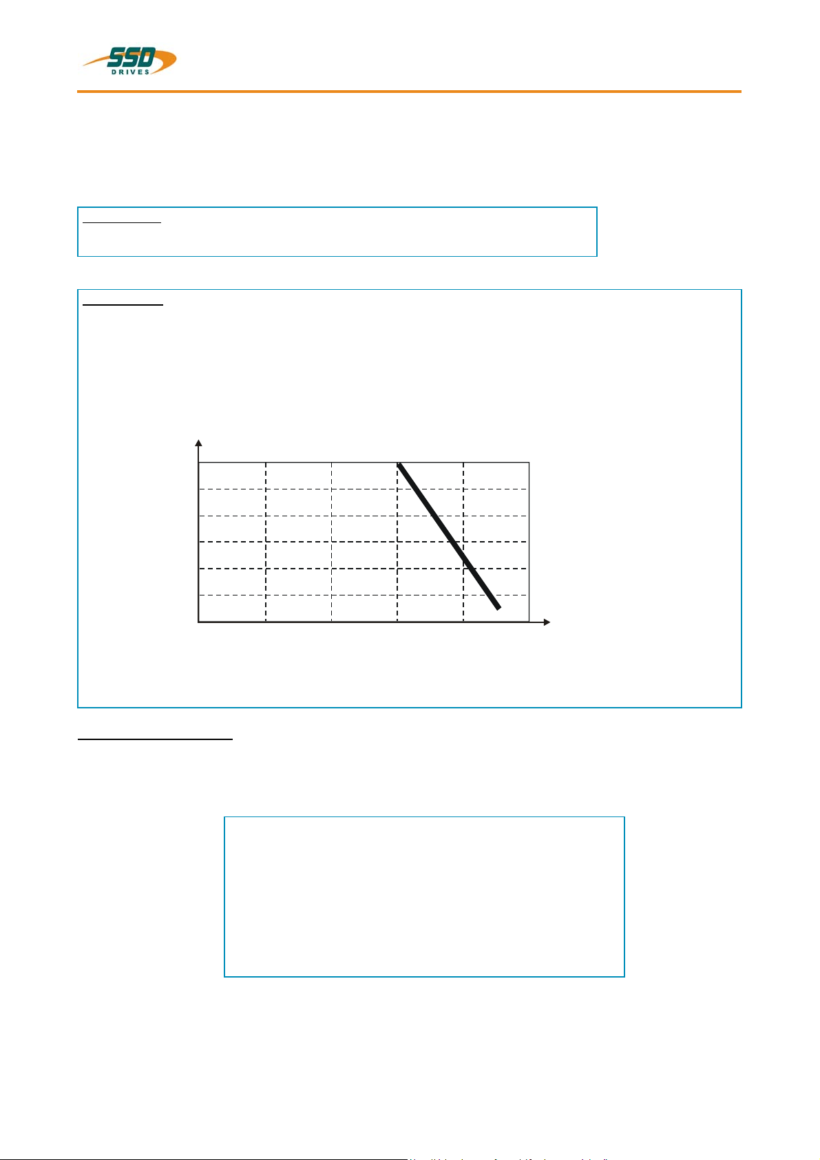
1.3.5 Single- and Three-Phase Supply
Due to the line-ripple of the DC-Bus, the rate of usable output voltage is reduced as follows.
This reduction affects the maximum attainable speed of the applied motor.
Three-phase
The unloaded output voltage will be reduced to approx. 90%, maximally 85
%
Single-phase
only servo drive 637f / ..02 up to 06
see the following diagram:
supply:
supply: 50 – 60 Hz
Derating of servo drive output voltag e in case of single-phase operationen
Output curr en t [A ]
RMS
12
10
8
6
4
Hint for parameterization:
To avoid unexpected tripping of the under voltage threshold, the parameter setting should be left on
default values (EASYRIDER
Required motor-terminal-voltage for specified speed.
2
0
0
20 40 60 80 100
Output voltage in % of unloaded condition
®
Windows – Software).
Approximation: (up to 3000RPM)
Ukl = 1,2 * (EMF * n / 1000) + I * (Rph + RL) [V]
Ukl Required motor voltage [V
EMF Back-EMF of motor [V
Rph Resistance of motor (between terminals) [
RL Line resistance of motor cable [
I Motor-current [A
RMS
[%]
]
RMS
] / 1000 RPM
RMS
Ω]
Ω]
]
________________________________________________________________________________________________________________________________________________________________________________________________________________________
07-02-10-01-E-V0505.doc Product Manaul Type: 637f 19
1 General Information
Range Data
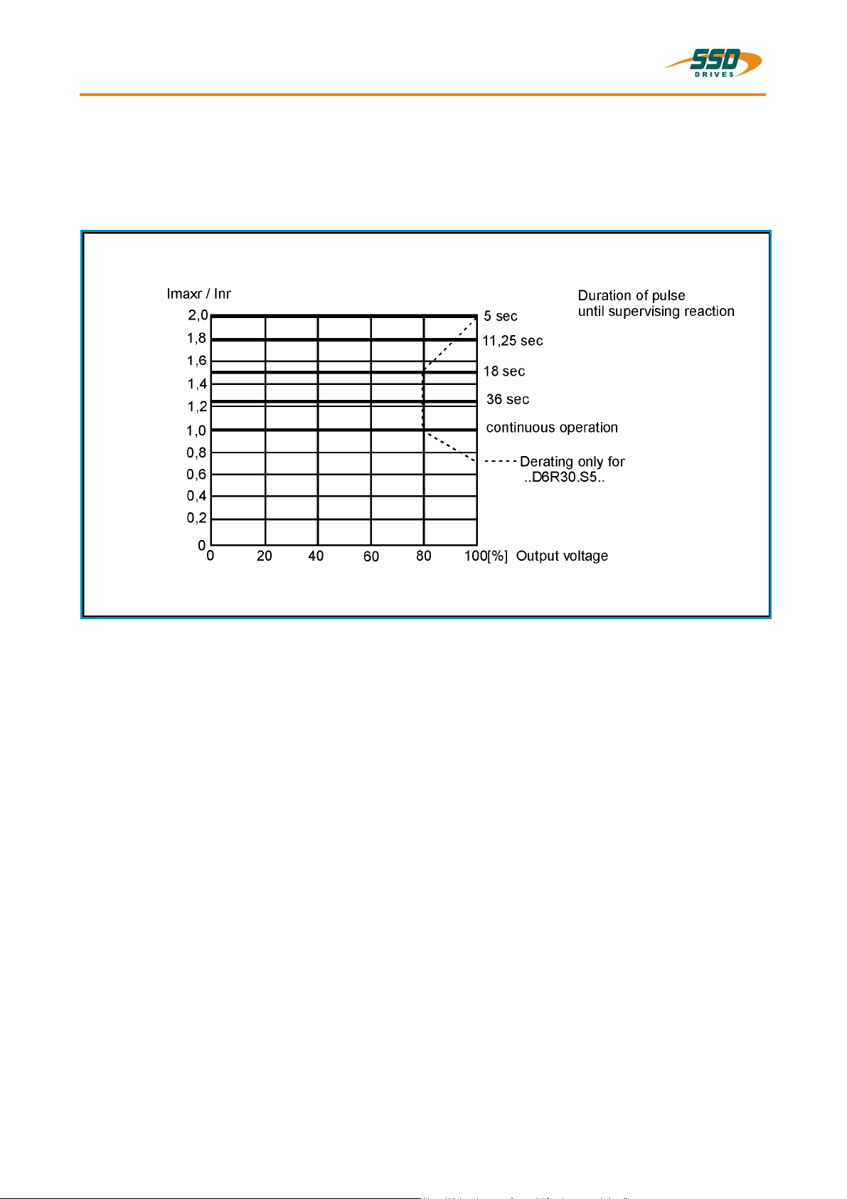
1.3.6 Output Power
In case of continuous operation in the full-load range, the limits as shown in the following diagram
need to be respected.
Typical servo applications are not affected by this restriction. (S3 operation: Start/Stop).
________________________________________________________________________________________________________________________________________________________________________________________________________________________
20 Product Manual Type: 637f 07-02-10-01-E-V0505.doc
2
General Information 1
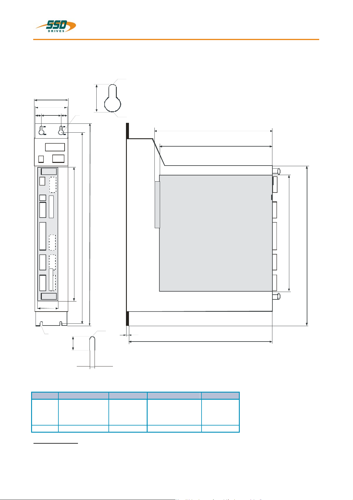
1.4 Dimensions
1.4.1 Dimensions for Compact Device and Plug-In Module
front side
D
A
18
B
D
C
d
400
262
386
Ø 5,
detail
Ø 10
243
220
plug -in modu l e
space for fan
a
d
Ø 5,2
1,6
280
detail
9
5,2
637f/K D6R 02...10 width 637f/K D6R 16...30 width
A 65,0 mm 14 HP 104,6 mm 20 HP
B 60,0 mm 100,0 mm
C 30,0 mm 71,0 mm
D 14,5 mm 14,5 mm
a 40,2 mm 8 HP 80,4 mm 16 HP
1 HP ≈ 5,08mm
Important Note:
You will need additional space on the front side, of approx. 70 mm, for the signal mating plugs!
233
304
________________________________________________________________________________________________________________________________________________________________________________________________________________________
07-02-10-01-E-V0505.doc Product Manaul Type: 637f 21
1 General Information
Dimensions
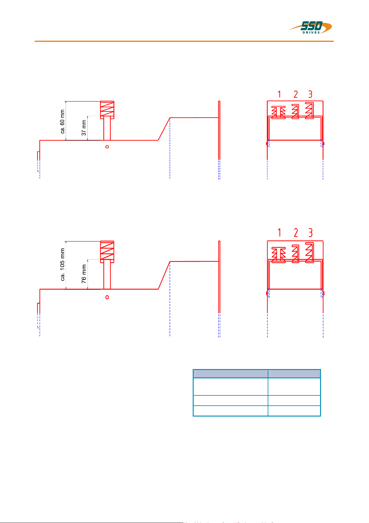
1.4.2 EMC-Clip (optional)
1.4.2.1 For 8 HP Drive
side view front view
1.4.2.2 For 16 HP Drive
side view front view
EMC - Clip for
Feedback cable
1
(e.g. Resolver)
Mains cable
Motor cable
2
3
Meaning:
1,2,3 = cage clamp terminals
________________________________________________________________________________________________________________________________________________________________________________________________________________________
22 Product Manual Type: 637f 07-02-10-01-E-V0505.doc
2 Connector Assignments and Functions
Connector Assignments and Functions 2
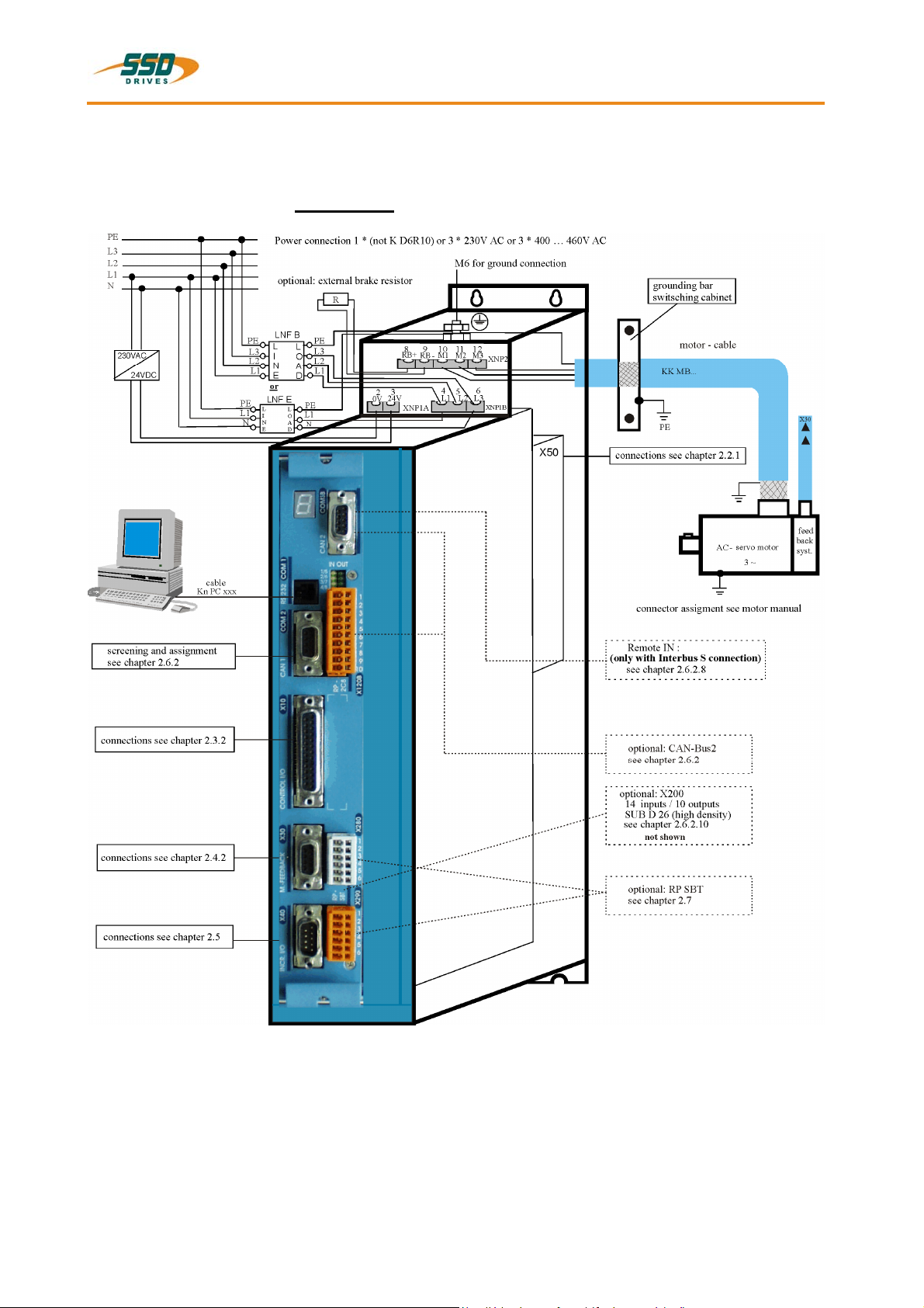
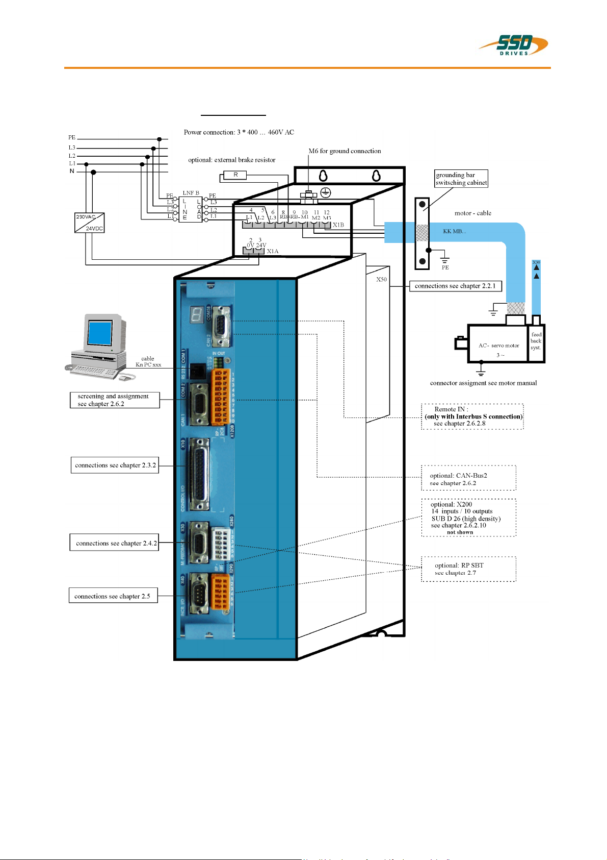
2.1 General View of Connections for Compact Device 637f/ K D6R 02 – 10
2.1.1 637f/K D6R 02...10 Width 14 HP
________________________________________________________________________________________________________________________________________________________________________________________________________________________
07-02-10-01-E-V0505.doc Product Manaul Type: 637f 23
2 Connector Assignments and Functions
General View of Connections for Compact Device 637f/ K D6R 02 – 10
2.1.2 637f/K D6R 16...30 Width 20 HP
________________________________________________________________________________________________________________________________________________________________________________________________________________________
24 Product Manual Type: 637f 07-02-10-01-E-V0505.doc
Connector Assignments and Functions 2
2.2 Connector Pin Assignments and Contact Functions
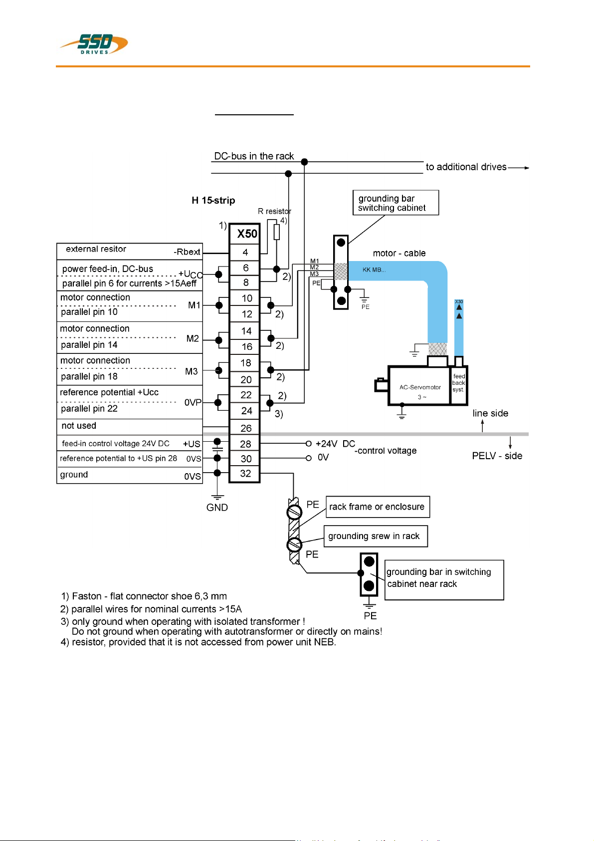
2.2.1 Power Connections for Plug-In Module 637f/D6R
(at the rear of the rack)
(H15 multiple pin strip according to DIN 41612)
________________________________________________________________________________________________________________________________________________________________________________________________________________________
07-02-10-01-E-V0505.doc Product Manaul Type: 637f 25
2 Connector Assignments and Functions
2.3 Signal Connections
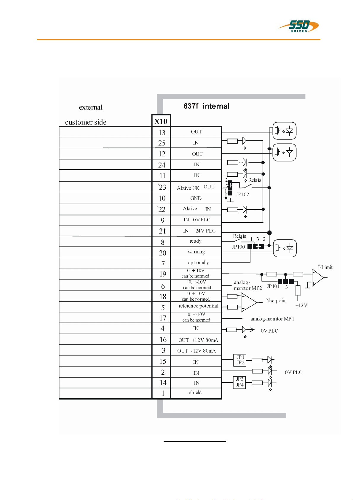
2.3.1 Control Signal Plug X10 - SUB D25 Socket
Complete Representation X10
Reference to pin 22 & pin 23: With controllers with option module SBT, kindly note the extended
functions of these signals (see documentation 07-02-10-02-E-Vxxxx).
________________________________________________________________________________________________________________________________________________________________________________________________________________________
26 Product Manual Type: 637f 07-02-10-01-E-V0505.doc
Connector Assignments and Functions 2
Signal Connections
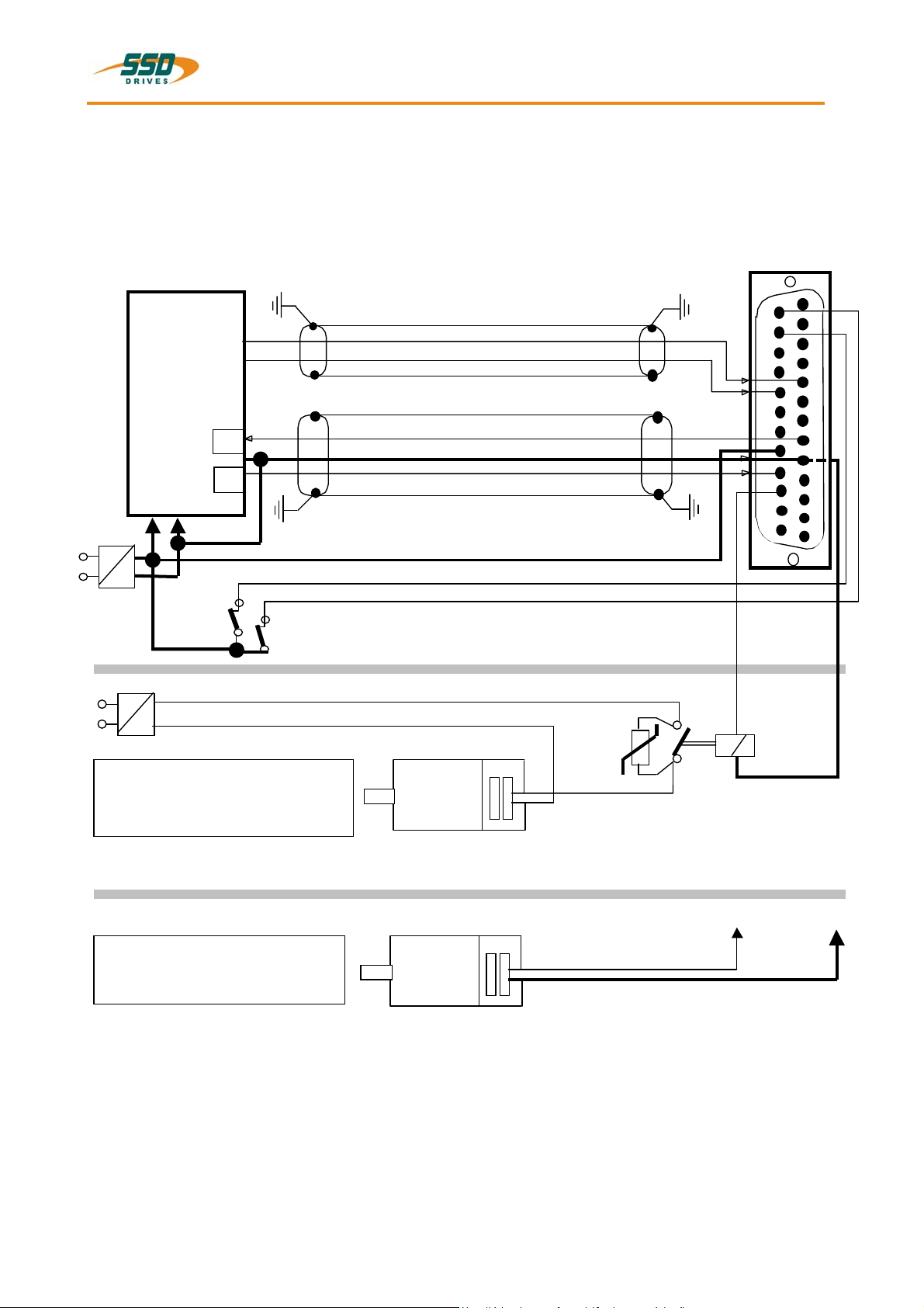
Control Signal Plug X10 - SUB D25 Socket
Connection Example
(without option SBT)
drive side
control signal plug X10
model: SUB D 25
PLC
1)
1)
24V
0V
-
+
2)
L1
~
=
N
PELV-
isolation
2)
L1
~
N
Supply may be used for mutliple brakes
=
+24V (br)
0V (br)
sprea d out
sprea d out
mecanical
limit switches
+/- 10V
output ready
0V refer ence point, I/ O-s u pply
input active
+24V, I/O-supply
option: brake
V1
K1
22
14
15
16
17
18
19
20
21
23
24
25
1
2
3
4
5
6
7
8
9
10
11
12
13
Brake-Connection Type A :
when Is olation-Type of Break - Inst allation is
Basic (not PELV). The PELC - Isolation of
Control - Cirquit s i s uneffect ed.
Eurotherm
AC-Servomotor
3 ~
option: brake
Brake-Connection Type B :
when isol ation-type of break - in sta llation is
PELV.
AC-Servomotor
3 ~
1) Security- and supervising logic, to be programmed by user !
2) IMPORTANT:
The power-supply for the motor-brake has to be adapted to the type of brake.
Voltage-Drops caused by long cables also may effect malfunctions of the brake.
V1: Varistor e.g.. Siemens Q69X3431, 38 V DC
K1: Couple-relais min. 2A,/60VDC PELV Isolation
X10.23 X10.9
________________________________________________________________________________________________________________________________________________________________________________________________________________________
07-02-10-01-E-V0505.doc Product Manaul Type: 637f 27
 Loading...