


RTS 2nd Generation SERVO AMPLIFIER
1
PVD 3487 GB 03/2004
CONTENTS
SAFETY INSTRUCTIONS ……………………………………………………………………………3
1. GENERAL 5
2. TECHNICAL SPECIFICATIONS 6
2.1 RTS Servo amplifier performance chart 7
2.2 Block diagram 8
3. DIMENSIONS, LABELLING, 9
3.1 Dimensions 9
3.2 Labelling 23
4. - ELECTRICAL CONNECTIONS 24
4.1 General Wiring Requirements 24
4.1.1 Appliance handling 24
4.1.2 Electromagnetic compatibility 24
4.2 RTS Servo amplifier connection 25
4.3 Front Panel 30
4.4 Terminal blocks X1, X2 AND X3 35
4.5 Terminal block X2 connection 38
4.6 Terminal block X3 connection 38
4.7 Accessories 39
4.7.1 Plug-in Customisation card 39
4.7.2 Extra choke 39
4.7.3 Transformer 40
4.7.4 Mains filter 40
5. LED DISPLAYS 49
6. SERVO AMPLIFIER ADAPTATION 50
7. COMMISSIONING 51

RTS 2nd Generation SERVO AMPLIFIER
2
PVD 3487 GB 03/2004
7.1
Speed loop rapid adjustment 52
7.2 Complete speed loop adjustment 53
7.3 Diagnostic helpI 55
7.4 Calibration 56
7.4.1 Tachometric generator voltage calibration (R104) 58
7.4.2 Rated speed selection (R105) 59
7.4.3 Pulse current adjustment (R113) 60
7.4.4 Current limitation by external resistance or external voltage (terminal block X1) 60
7.4.4.1 By external resistance 60
7.4.4.2 By external voltage 60
7.4.5 Time constant adjustment I = f(t) (R109) 61
7.4.6 Adjustment of function I = f(t) (R103) 61
7.4.7 Adjustment of current limitation curve versus speed I F(n) (R131 - 132) 62
7.4.8 Calibration of function U - RI (R133 - R134) 63
7.4.9 Tripping limit calibration (R135) 64
7.4.10 Current loop gain adaptation to motor inductance (R136) 64
7.4.11 dc voltage calibration (RB) 65
Characteristics and dimensions subject to change without notice.
SSD Parvex SAS
8 Avenue du Lac / B.P 249 / F-21007 Dijon Cedex
Tél. : +33 (0)3 80 42 41 40 / Fax : +33 (0)3 80 42 41 23
www.SSDdrives.com
YOUR LOCAL CORRESPONDENT
RTS 2nd Generation SERVO AMPLIFIER
3
PVD 3487 GB 03/2004
SAFETY
Servodrives present two main types of hazard :
- Electrical hazard
Servoamplifiers may contain non-insulated live AC or DC
components. Users are advised to guard against access to live
parts before installing the equipment.
Even after the electrical panel is de-energized, voltages may be
present for more than a minute, until the power capacitors have
had time to discharge.
Specific features of the installation need to be studied to prevent
any accidental contact with live components :
- Connector lug protection ;
- Correctly fitted protection and earthing features ;
- Workplace insulation
(enclosure insulation humidity, etc.).
General recommendations :
• Check the bonding circuit;
• Lock the electrical cabinets;
• Use standardised equipment.
- Mechanical hazard
Servomotors can accelerate in milliseconds. Moving parts must be
screened off to prevent operators coming into contact with them.
The working procedure must allow the operator to keep well clear
of the danger area.
All assembly and commissioning work must be done by qualified
personnel who are familiar with the safety regulations (e.g. VDE
0105 or accreditation C18510).
RTS 2nd Generation SERVO AMPLIFIER
4
PVD 3487 GB 03/2004
Upon delivery
All servoamplifiers are thoroughly inspected during manufacture and tested at length for bugs
before shipment.
• Unpack the servoamplifier carefully and check it is in good condition.
• Also check that data on the manufacturer's plate comries with data on the order
acknowledgement.
If equipment has been damaged during transport, the addressee must file a complaint with the
carrier by recorded delivery mail within 24 hours
.
Caution
:
The packaging may contain essential documents or accessories, in particular :
• User Manual,
• Connectors.
Storage
Until installed, the servoamplifier must be stored in a dry place safe from sudden temperature
changes so condensation cannot form.
Special instructions for setting up the equipment
CAUTION
For this equipment to work correctly and safely it must be
transported, stored, installed and assembled in accordance with
this manual and must receive thorough care and attention..
Failure to comply with these safety instructions may lead to
serious injury or damage.
The cards contain components that are sensitive to electrostatic
discharges. Before touching a card you must get rid of the static
electricity on your body. The simplest way to do this is to touch a
conductive object that is connected to earth (e.g. bare metal
parts of equipment cabinets or earth pins of plugs).

RTS 2nd Generation SERVO AMPLIFIER
5
PVD 3487 GB 03/2004
1. GENERAL
The RTS servo amplifier is designed for four-quadrant control of DC servo motors up to
mechanical powers of 2500 W.
It incorporates power and chopping supplies, including the energy dissipation resistor for some
versions.
This integration makes for easier wiring and allows front panel access for a more user-friendly
appliance.
Two formats are available :
Wall mounted type with rear angle bracket
Europe single 3 u DIN rack type.
Several axes can thus be included in one 19" rack.
TECHNOLOGY
• CMS components (surface mounted).
• Genuine galvanic insulation to prevent sensitivity to interference.
• Hall effect current sensor.
• Chopping frequency 17 kHz.
• Speed bandwidth up to 150 Hz.
• Integrated short circuit protection.
• Speed range : With tachometer 1: 10 000
U-RI 1 : 10
• ± 10 V differential reference for speed or current.
• Differential tachometer input.
FUNCTIONS
• Switchable tachometer control in U-RI.
• Current or speed control.
• Current reduction with speed.
• Current reduction with temperature.
• External current reduction.
• Zero speed adjustment.
• Zero torque adjustment.
• Fault clearance (RESET).
• Analogue speed or torque information.
• Servo amplifier status relay.
• ± 15 V available.
RTS 2nd Generation SERVO AMPLIFIER
6
PVD 3487 GB 03/2004
- COMPLIANCE WITH STANDARDS
RTS bears the CE mark under European Directive 89/336/EEC as amended by Directive 93/68/EEC on
electromagnetic compatibility. This European Directive refers to the harmonised generic standards
EN50081-2 of December 1993 (Electrical Compatibility - Generic Standard for Emissions - Industrial
Environments) and EN50082-2 of June 1995 (Electromagnetic Compatibility - Generic Standard for
Immunity - Industrial Environments). These two harmonised generic standards are based on the following
standards :
• EN 55011 of July 1991 : Radiated and conducted emissions
• EN 50140 of August 1993 and ENV 50204 : Immunity to radiated electromagnetic fields
• EN 61000-4-8 of February 1994: Mains frequency magnetic fields
• EN 61000-4-2 of June 1995 : Electrostatic discharge
• ENV 50141 of August 1993 : Interference induced in cables
• EN 61000-4-4 of June 1995 : Rapid transient currents
Compliance with the reference standards above implies adherence to the instructions and wiring diagrams
in the technical documents supplied with the appliances.
Incorporation in Machinery
The design of the equipment means it can be used in machinery covered by Directive 89/392/EEC (Machine
Directive) provided that it is integrated (or incorporated and/or assembled) in accordance with the rules-ofthe-art by the machinery manufacturer and in keeping with the instructions in this booklet.
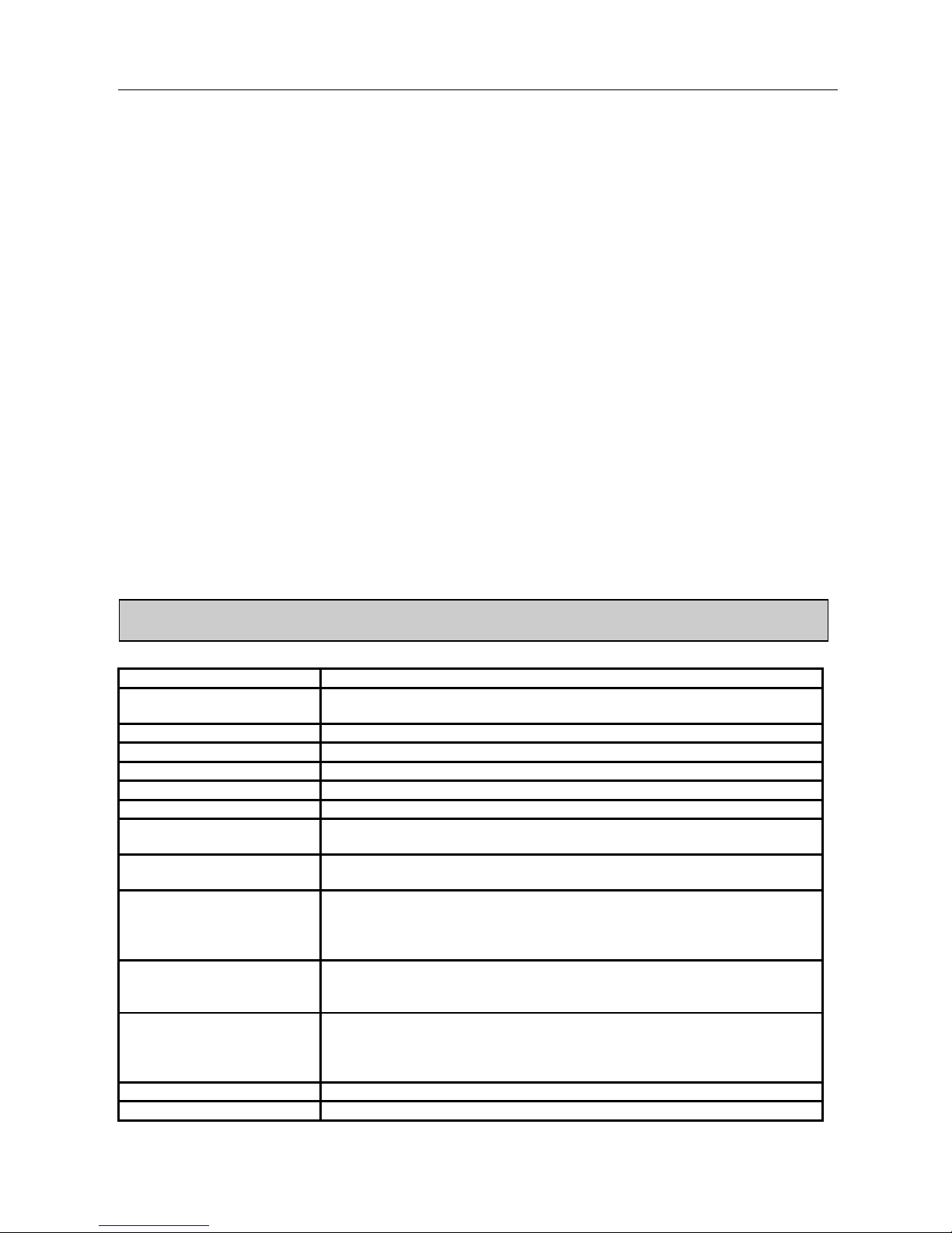
2. TECHNICAL SPECIFICATIONS
Power reduction with altitude Above 1000 m, 10% fall in useful power per 1000 m up to maximum 4000 m
Operating temperature
Normal use: 0 to + 40°C
Above 40°C, 35% fall in useful power per 10°C up to maximum 60°C
Storage temperature -30°C to +85°C
Chopping frequency 17 kHz current
Technology Photocoupler controlled MOS transistors.
Bandwidth in current Up to 1500 Hz
Bandwidth in speed Up to 150 Hz at 90° phase shift
Tachogenerator
maximum voltage
100 V at input
Speed range
1:10 000 with tachogenerator
1:10 with armature reaction (U - RI)
Static precision of speed for
load variation of 0 at In and
for servo amplifier rated
voltage
From Nmax to Nmax/100 +/- 0.5%
From Nmax/100 to Nmax/1000 +/-1.5%
From Nmax/1000 to Nmax/10 000 +/-10%
U-RI control, from Nmax to Nmax/10 +/-20%
Current control
Precision
Linearity
+/-2% of rated current at 25°C
+/-1% of rated current at 25°C
Electrical protection
- Galvanic insulation of power bridge
- Magnetic current sensor
- Power outputs protected against phase-to-phase and phase
to-ground short-circuits
Connections Plug-in terminal blocks on front panel
Protection IP20, IP20 for shrouded versions
RTS 2nd Generation SERVO AMPLIFIER
7
PVD 3487 GB 03/2004
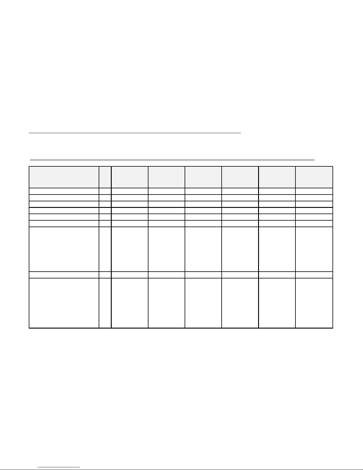
2.1 RTS Servo amplifier performance chart
RTS CHARACTERISTICS
at 40°C ambient temperature
3/10-40M
single-phase
10/20-60
single/three-
12/24---B
battery
12/24-130T
three-phase
20/40-130T
three-phase
16/32-190T
three-phase
Input voltage rangeV 18/36Vac 18/56Vac 16/60Vdc 58/116Vac 58/116Vac 82/164Vac
Rated input voltage V 32Vac+/-10% 48Vac+/-10% 100Vac+/-10% 100Vac+/-10% 135Vac+/-10%
Maximum output voltage V= 40 60 V battery -2V 130 130 190
Permanent output current A 3 10 12 12 20 16
Pulse current (2 sec) A 10 20 24 24 40 32
Minimum motor choke mH 1 0.4 0.4 0.8 0.4 0.8
BRAKING ENERGY
DISSIPATION CAPACITY
Mean power
Max pulse power
(4% of cycle)
Maximum, non-repetitive
W
W
sec
15W (option)
400 (option)
2
30
800
1
without
without
-
100
2500
1
180
4500
2
180
4500
2
Losses dissipated by RTS W 15 40 30 80 120 130
DIMENSIONS H x L x D (mm)
Rack version (single-phase)
Rack version (three-phase)
Wall-mounted (single-phase)
Wall-mounted (three-phase)
Rack/wall-mounted wei
g
ht
mm
mm
mm
mm
kg
130/51/216
--
150/61/212
--
0.8/1
--
130/51/216
180/61/212
150/61/212
0.8/1.2
--
130/51/216
(battery)
--
150/61/212
(battery)
0.8/1
--
130/61/216
--
150/92/212
0.85/1.8
--
--
--
150/115/221
1.9
--
--
--
150/115/221
1.9

RTS 2nd Generation SERVO AMPLIFIER
8
PVD 3487 GB 03/2004
2.2 Block diagram

RTS 2nd Generation SERVO AMPLIFIER
9
PVD 3487 GB 03/2004
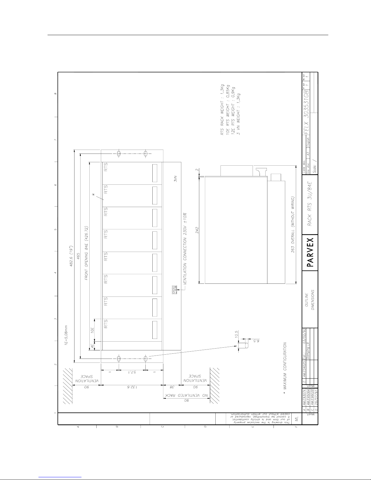
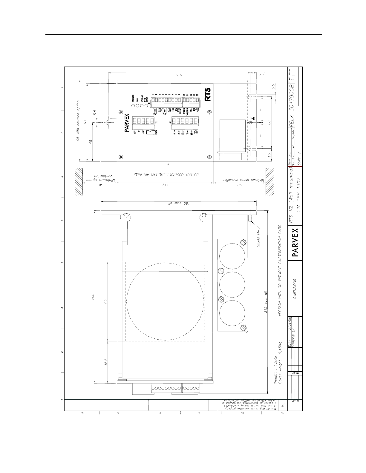
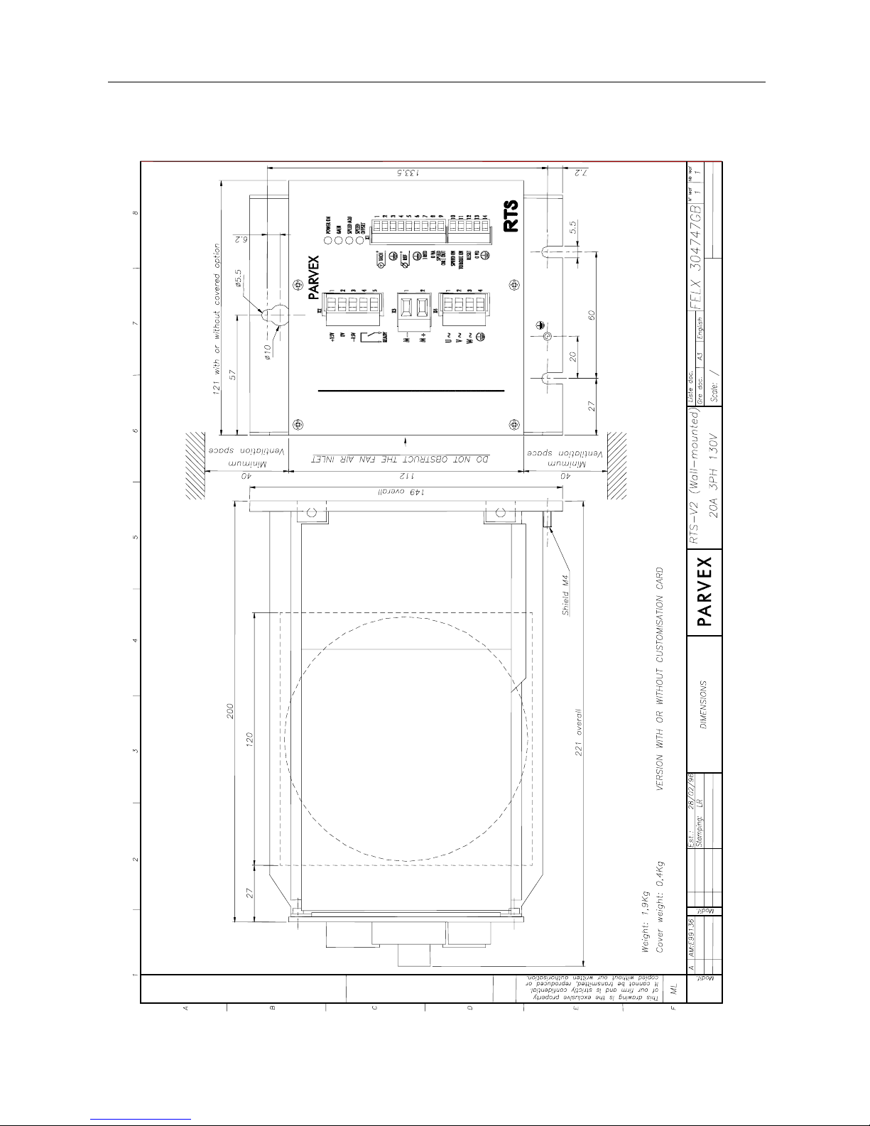
3. DIMENSIONS, LABELLING,
3.1 Dimensions
RTS servo amplifiers are available in two formats for vertical mounting :
- in single Europe 3U DIN rack, in two widths 10" and 19".
- wall- or panel-mounted, with rear angle bracket.
Racks are available with or without ventilation, while RTS wall-mounted versions have individual
ventilation where required (RTS 12/24-130T, RTS 20/40-130T and RTS 16/32-190T). Unventilated
racks are for RTS 3/10-40M only.
230 V single-phase fan connection : To terminal block located at the bottom of the rack front
panel.
- Power consumption : RACE234V22, 2 x 15W fans.
RACE238V32, 3 x 15W fans.
CODE WIDTH DIMENSIONS
RACE234 42E (10’’) FELX 303532 (p12)
RACE234V22 (
f
an-cooled
) 42E (10’’) FELX 303532(p12)
RACE238 84E (19’’) FELX 303531 (p11)
RACE238V32 (
f
an-cooled
) 84E (19’’) FELX 303531 (p11)
Dimensions :
RTS
Parvex Ref.
Input supply
Compulsor
y
ventilation
Fan supply
voltage
Dimensional drawing ref.
Without
customisation
card
With
customisation
card
R
RTS 3/10-40M RTS 4104-301 Single-phase
No
A
*RTS 6104-301
C
K
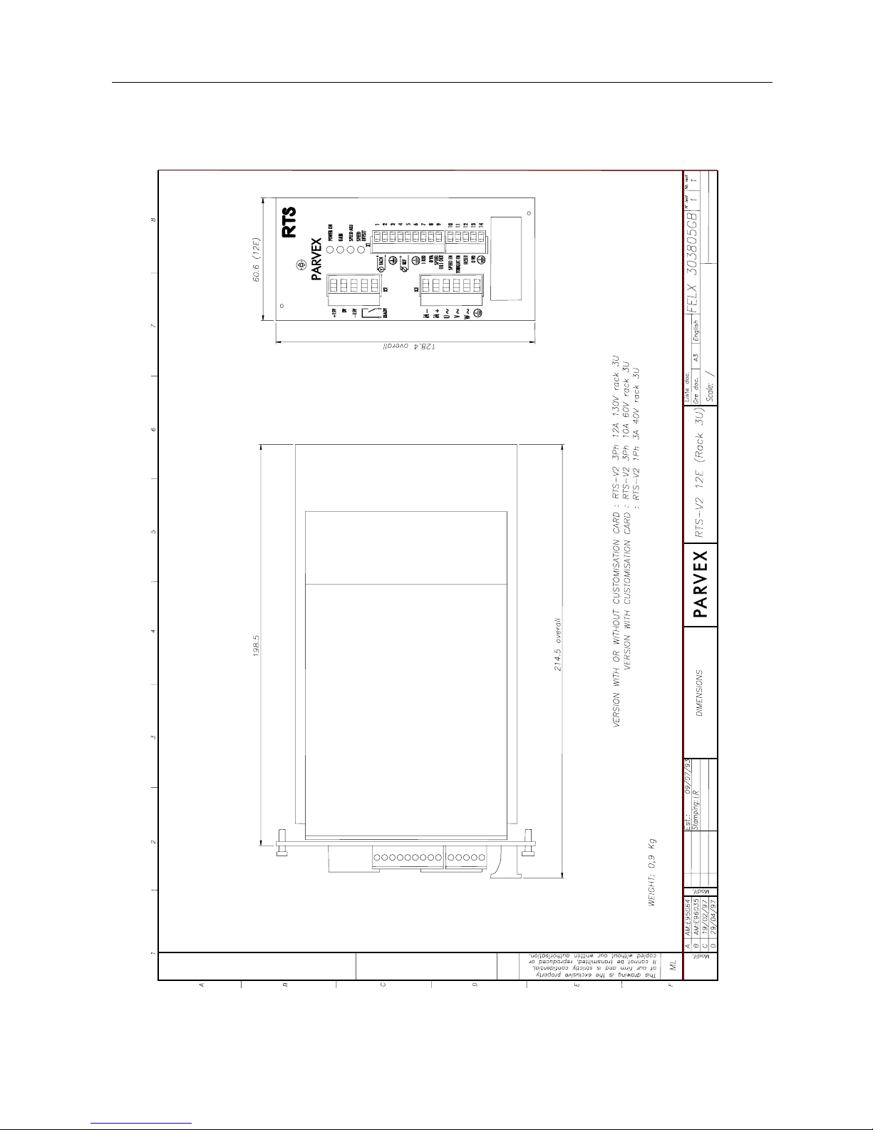
RTS 10/20-60T RTS 43060102R Three-phase FELX 303440 FELX 303805
V
*RTS 63060102R
(p13) (p15)
e
Yes 230 V
r
s
Single-phase
i
o
RTS 12/24---B RTS 42BA0102 Battery FELX 303814
(p14)
n
RTS 12/24-
130T
RTS 43130102R
* RTS 63130102R
Three-phase
FELX 303805
(p15)
* With personalizing card RZ6602

RTS 2nd Generation SERVO AMPLIFIER
10
PVD 3487 GB 03/2004
RTS
PARVEX Ref.
Input supply
Ventilation
Supply
Dimensional
drawing
(with or without
customisation
card)
W
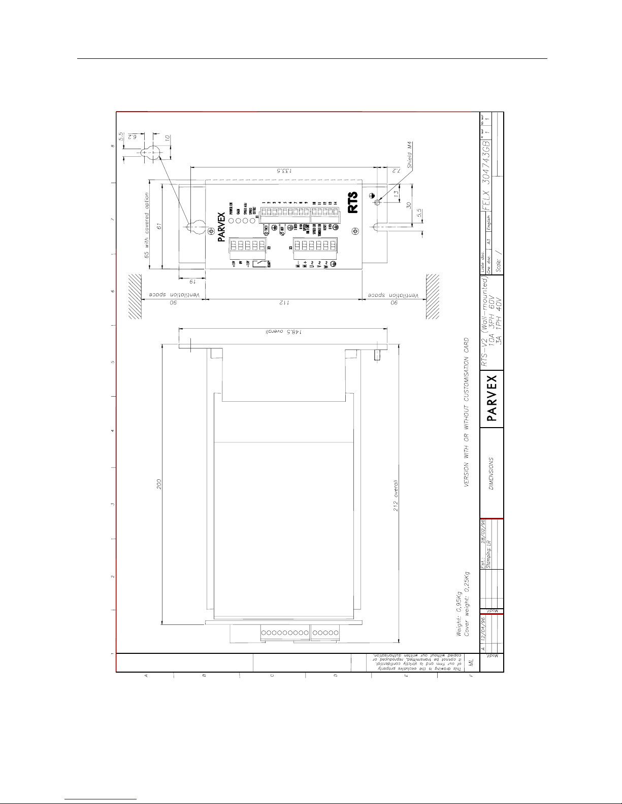
RTS 3/10-40M RTS 5104-301 Single-phase Not
A
* RTS 7104-301 fan-cooled
L
FELX 304743
L
RTS 10/20-60T RTS53060102R Three-phase Not
(p16)
*RTS73060102R fan-cooled
M
FELX 304749
O
RTS 12/24---B RTS 52BA0102 Battery Not
(p21)
U
* RTS 72BA0102 fan-cooled
N
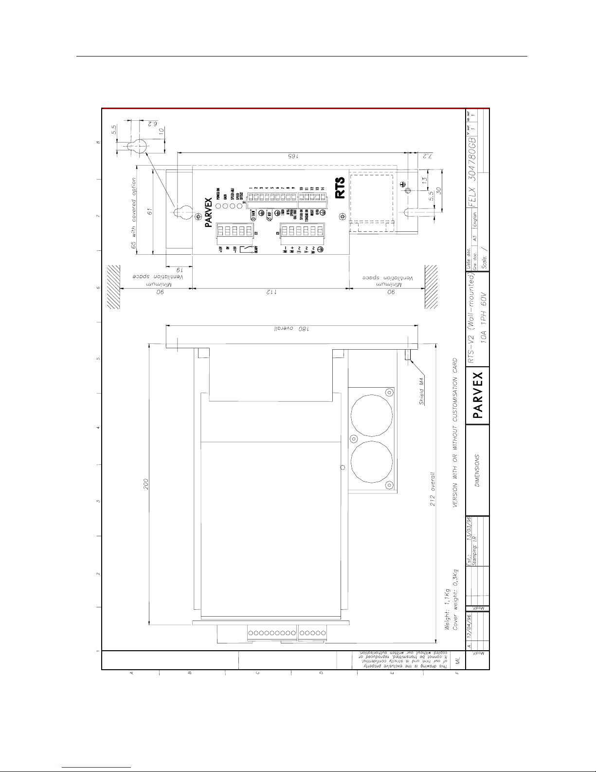
FELX 304780
T
RTS 10/20-60M RTS 51060102R Single-phase Not
(p17)
E
* RTS 71060102R fan-cooled
D
FELX 304790
RTS 12/24-130M RTS 51130102R
* RTS 71130102R
Single-phase fan-cooled
(p18)
FELX 304745
RTS 12/24-130T RTS 53130102R
* RTS 73130102R
Three-phase fan-cooled connection
Internal
(p19)
V
e
FELX 304747
r
s
RTS 20/40-130T RTS 53130204R
* RTS 753130204R
Three-phase fan-cooled connection
Internal
(p20)
i
o
FELX 304746
n
RTS 16/32-190T RTS 53190103R Three-phase fan-cooled connection
(p22)
* 753190103R Internal
* With customisation card RZ6602
RTS 2nd Generation SERVO AMPLIFIER
11
PVD 3487 GB 03/2004

RTS 2nd Generation SERVO AMPLIFIER
12
PVD 3487 GB 03/2004

RTS 2nd Generation SERVO AMPLIFIER
13
PVD 3487 GB 03/2004

RTS 2nd Generation SERVO AMPLIFIER
14
PVD 3487 GB 03/2004
RTS 2nd Generation SERVO AMPLIFIER
15
PVD 3487 GB 03/2004
RTS 2nd Generation SERVO AMPLIFIER
16
PVD 3487 GB 03/2004
RTS 2nd Generation SERVO AMPLIFIER
17
PVD 3487 GB 03/2004
RTS 2nd Generation SERVO AMPLIFIER
18
PVD 3487 GB 03/2004

RTS 2nd Generation SERVO AMPLIFIER
19
PVD 3487 GB 03/2004
RTS 2nd Generation SERVO AMPLIFIER
20
PVD 3487 GB 03/2004

RTS 2nd Generation SERVO AMPLIFIER
21
PVD 3487 GB 03/2004

RTS 2nd Generation SERVO AMPLIFIER
22
PVD 3487 GB 03/2004

RTS 2nd Generation SERVO AMPLIFIER
23
PVD 3487 GB 03/2004
3.2 Labelling
RTS SERVO AMPLIFIER IDENTIFICATION
Each RTS servo amplifier has an identification label affixed either on the metal plate at the rear for
wall-mounted versions or on the side of the heat sink for rack versions.
The information should be recorded and stored as with the information about the corresponding
servo motor. Remember to record the "A" and/or "B" label indications too.
SPECIMEN LABEL :
c RTS code d Number of phases
e Input voltage (ac) f Input current (ac)
g Output voltage (dc) h Output current (dc)
The output voltage and current values correspond to those of the RTS model (as in RTS servo
amplifier performance chart).
A self-adhesive label is placed on the RTS front panel. Label "A" records :
- N ---- :. servo amplifier serial number
- R----- :. type of motor associated with RTS.
- DT-V : emf of tachometric dynamo for 1000 rpm.
- 10V ----TR : reference value corresponding to maximum motor speed in rpm
(factory set).
Where the RTS is fitted with an RZ 6602 customisation card, some of these indications are
recorded on the self-adhesive label on the customisation card (label "B"). This label also
states the model of RTS.
LABEL "A" LABEL "B"
RTS --V --A
R----- DT-V
10V ----TR
N----
R----- DT-V
10V ----TR

RTS 2nd Generation SERVO AMPLIFIER
24
PVD 3487 GB 03/2004
4. - ELECTRICAL CONNECTIONS
4.1 General Wiring Requirements
4.1.1 Appliance handling
See the safety instructions given at the beginning of this manual. In particular, wait for all the front
panel LEDs to go off completely before doing any work on the servo-amplifier or servomotor.
4.1.2 Electromagnetic compatibility
EARTHING
Comply with all local safety regulations concerning earthing.
Utilize a metal surface as an earth reference plane (e.g. cabinet wall or assembly grid).
This conducting surface is termed the potential reference plate. All the equipment of an
electrical drive system is connected up to this potential reference plate by a low
impedance (or short distance) link. Ensure the connections provide good electrical
conduction by scraping off any surface paint and using fan washers. The drive will then
be earthed via a low impedance link between the potential reference plate and the earth
screw at the back of the RTS. If this link exceeds 30 cm, a flat braid should be used
instead of a conventional lead.
CONNECTIONS
Do not run low-level cables (resolver, inputs/outputs, NC or PC links) alongside what are
termed power cables (power supply or motor). Do not run the power supply cable and
the motor cables alongside one another otherwise mains filter attenuation will be lost.
These cables should be spaced at least 10 cm apart and should never cross, or only at
right-angles.
Except for the resolver signals, all low-level signals will be shielded with the shielding
connected at both ends. At the RTS end, the shielding is made continuous by the SubD connector mechanism.
The motor cables are limited to the minimum functional length. The yellow and green
motor cable lead must be connected to the box or front panel terminal block with the
shortest possible link.
This usually means shielded motor cable is not required. Chokes may also be inserted
into the motor phase leads.

RTS 2nd Generation SERVO AMPLIFIER
25
PVD 3487 GB 03/2004
MAINS FILTERING
The mains filter must be mounted as close as possible to the potential reference plate between
the mains and the power supply (p.46 and 47). Use shielded cable (or run the cable in metal
trunking).
Avoid running cables together, ahead of and after the filter.
Filters sometimes have high leakage currents. In this case, comply with the standard connection
diagrams when fitting them.
OTHER MEASURES
Self-inducting components must be protected against interference: brakes, contactor or relay
coils, fans, electro-magnets, etc.
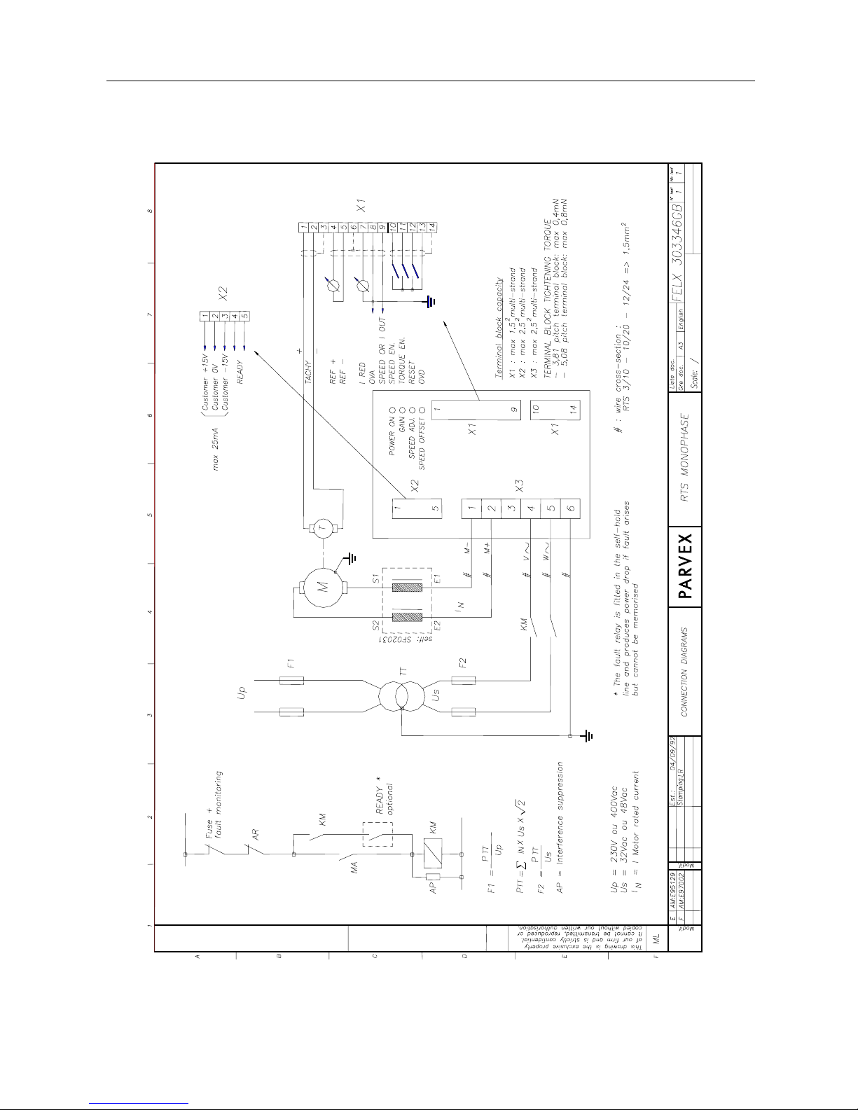
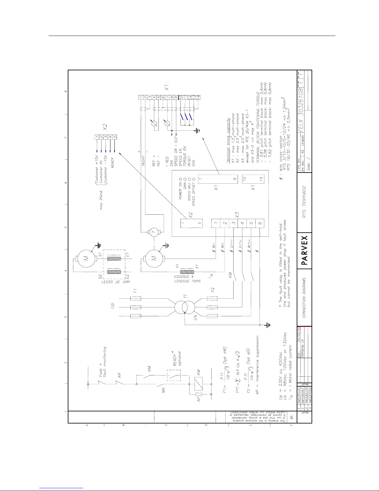
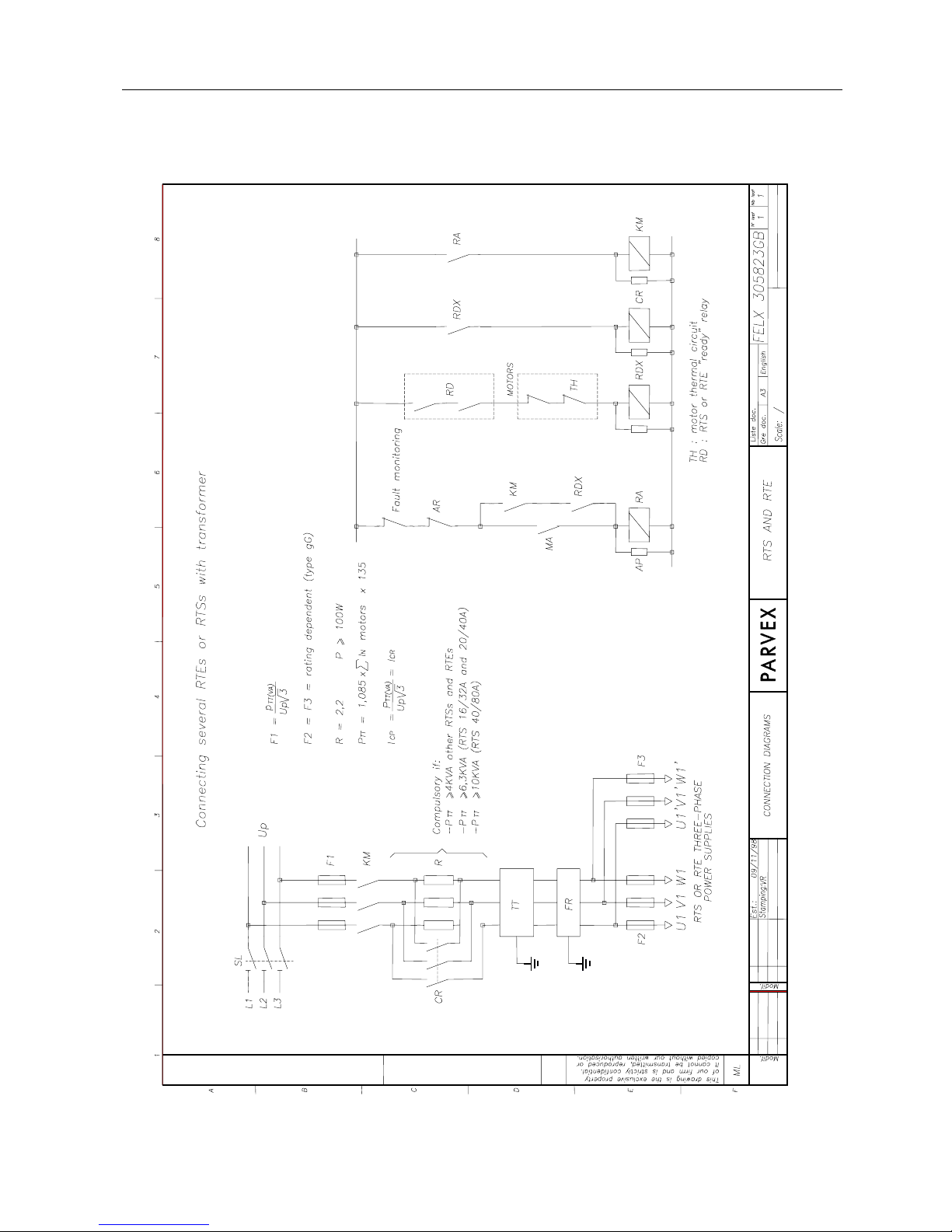
4.2 RTS Servo amplifier connection
As a supplement to the block diagram, see the appended diagrams :
- RTS single-phase FELX 303346 (p.26)
- RTS three-phase FELX 303261 (p.27)
- RTS battery FELX 303738 (p.28)
- Connecting serveral RTEs or RTSs with transformer FELX 305823 (p29)
The terminal block description and terminal functions are shown in the following pages :
The RTS servo amplifiers are factory set to match the characteristics of the servo motor to be
used or the application where known.
When the servo motor is fitted with a brake, adhere to the following activating sequence :
- Limit current (to a value less than the RTS setting),
- Engage brake,
- Cut RTS servo amplifier.
To restart, proceed as follows :
- limit current (as above),
- energise RTS,
- release brake,
- remove current limitation.
RTS 2nd Generation SERVO AMPLIFIER
26
PVD 3487 GB 03/2004
RTS 2nd Generation SERVO AMPLIFIER
27
PVD 3487 GB 03/2004

RTS 2nd Generation SERVO AMPLIFIER
28
PVD 3487 GB 03/2004
RTS 2nd Generation SERVO AMPLIFIER
29
PVD 3487 GB 03/2004

RTS 2nd Generation SERVO AMPLIFIER
30
PVD 3487 GB 03/2004
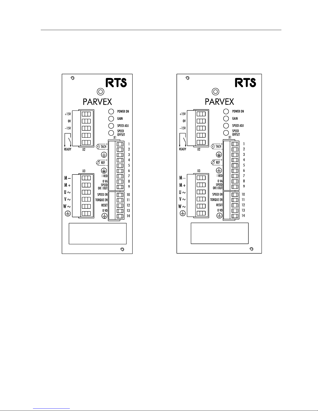
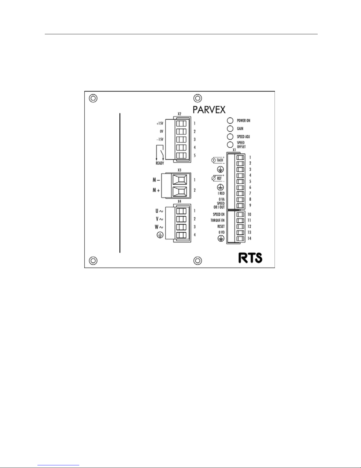
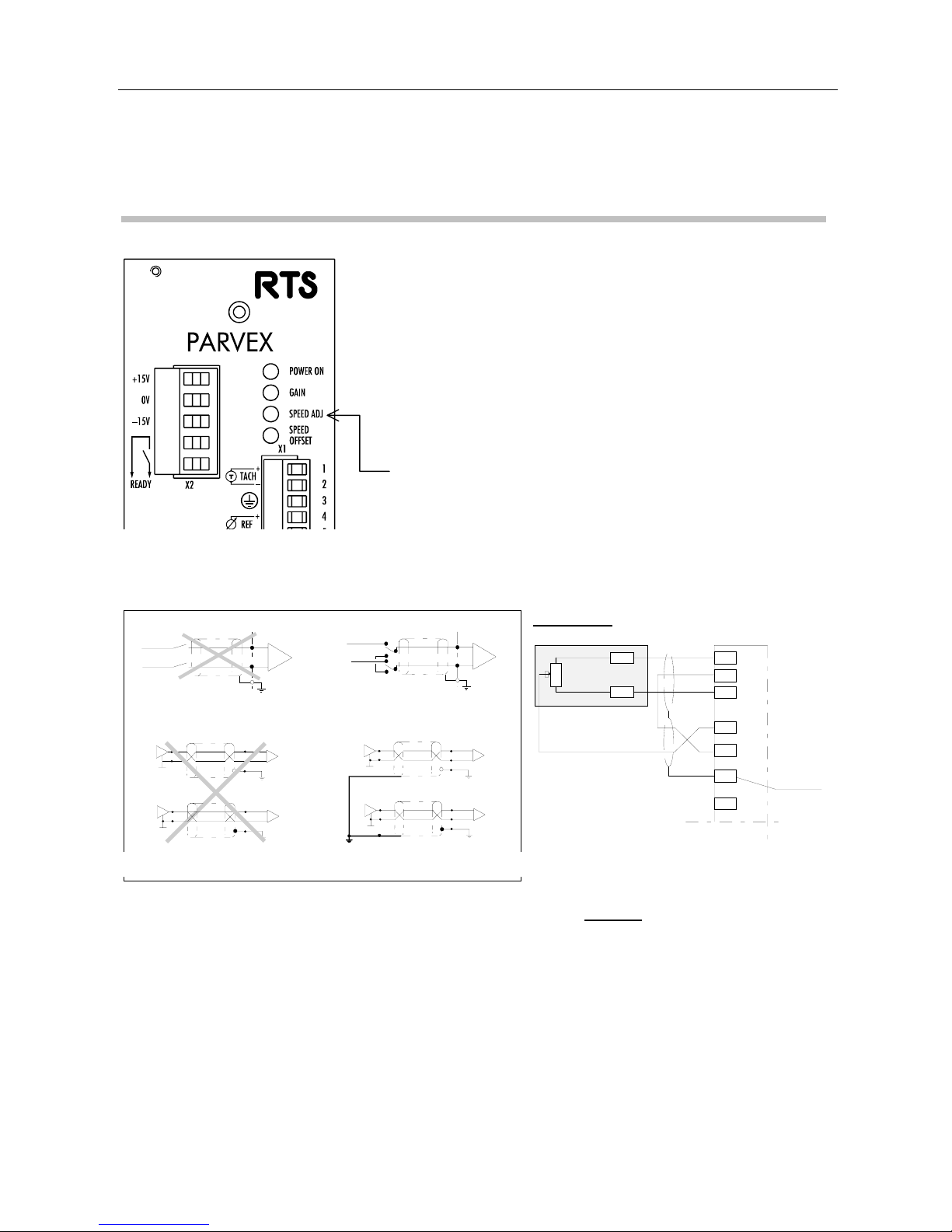
4.3 Front Panel
RTS V2 Battery (Rack) RTS V2 Battery (wall-mounted)
RTS 2nd Generation SERVO AMPLIFIER
31
PVD 3487 GB 03/2004
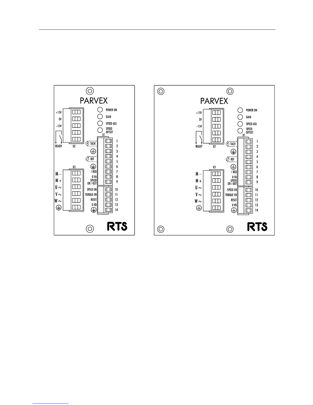
RTS V2 10 E (Rack) RTS V2 12 E (Rack)
RTS 2nd Generation SERVO AMPLIFIER
32
PVD 3487 GB 03/2004
RTS V2 12 E (wall-mounted) RTS V2 12 A / 130V (wall-mounted)
1PH and 3PH
RTS 2nd Generation SERVO AMPLIFIER
33
PVD 3487 GB 03/2004
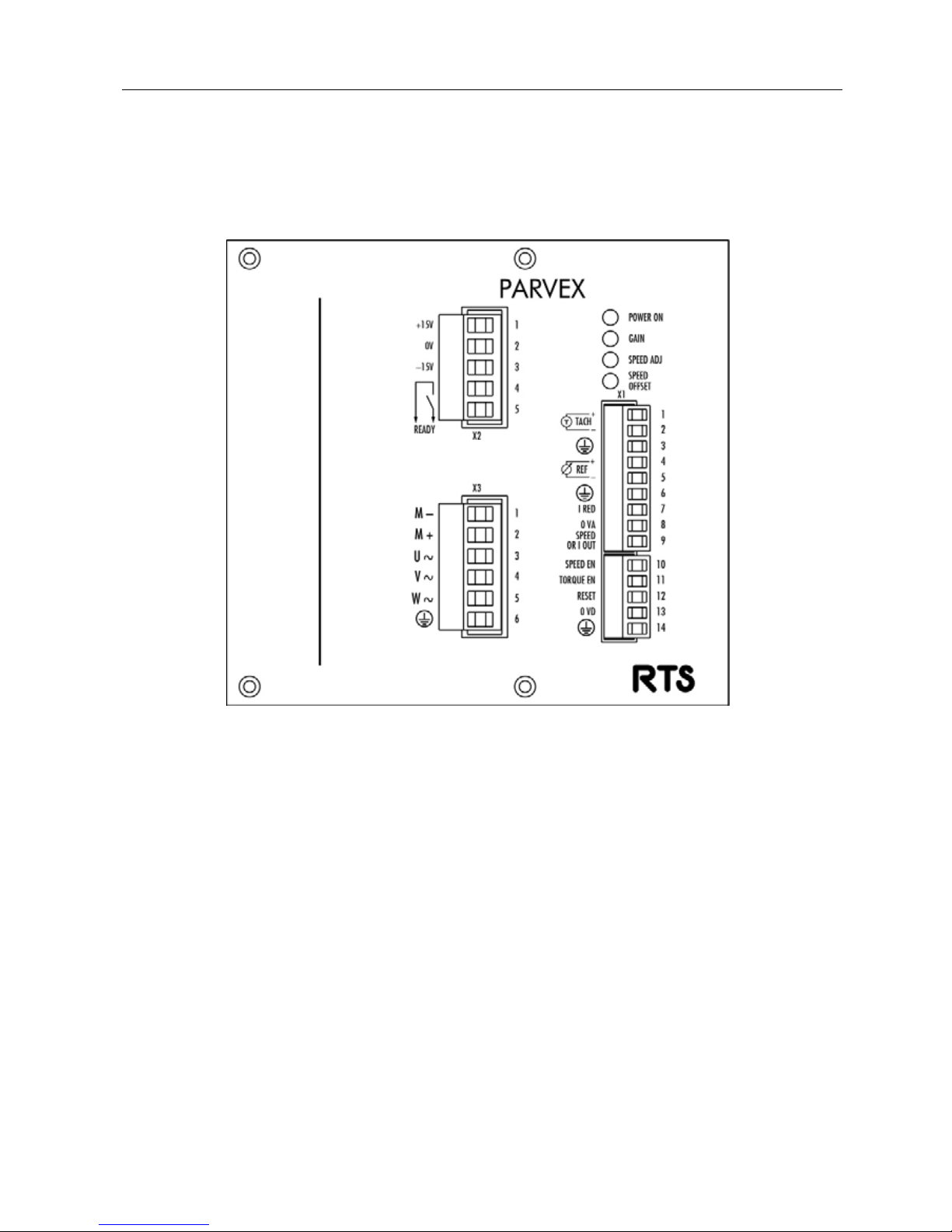
RTS V2 16 A / 190 V (wall-mounted)
RTS 2nd Generation SERVO AMPLIFIER
34
PVD 3487 GB 03/2004
RTS V2 20 A / 130 V (wall-mounted)
RTS 2nd Generation SERVO AMPLIFIER
35
PVD 3487 GB 03/2004
4.4 Terminal blocks X1, X2 AND X3
Torque value : terminal block X1, 0.4 Nm terminal blocks X2 and X3, 0.8 Nm.
Terminal block X1 front panel connection Recommended cable cross-section : 0.5 mm² -
- 1.5 mm² multi-strand. Use shielded cables with the shielding connected as stated below.
DESCRIPTION
N° NAME
TERMINAL BLOCK X1
1
2
3
4
5
6
TACH+
TACH-
REF+
REF-
I
I
-
I
I
-
Tacho differential inputs. Use
shielded cable with shielding
connected to terminal 3. Input
voltage must not exceed 100 V.
Tachometric cable shielding. Do not
connect shielding at tacho end.
Speed or current differential
reference depending on position of
selector switch S1.
± 10 V corresponds to rated motor
speed at speed reference.
Use shielded cable with shielding
connected to terminal 6.
Shielding, to be connected at
numerical control end also.
TERMINAL

RTS 2nd Generation SERVO AMPLIFIER
36
PVD 3487 GB 03/2004
DESCRIPTION
N° NAME
TERMINAL BLOCK X1
7
8
9
10
I RED
% I max
R(KΩ)
0 VA
SPEED
OR
I OUT
SPEED
EN.
I
-
O
I
A
nalogue reduction of current.
Reduction may be controlled either
by voltage or by resistor between 7
and 8.
This input may be used for example
when the servo motor is against a
mechanical abutment.
Resistor value :
10 30 50 70 90 100
3.32 10 22,1 39.2 56.2 infinity
0 V reference to be connected
internally in the casing
Signal providing speed or current
image depending on selector switch
S2 position.
± 10 V corresponds to max speed or
current value. (Pulse current value
shown in RTS characteristics chart).
See also identification section.
Typical uses :
motion synchronisation, master-slave
mode, cutting tool wear monitoring...
To be connected via an external
contact to terminal 13 to enable
speed reference. Typical uses : limit
switch, emergency stop
TERMINAL

RTS 2nd Generation SERVO AMPLIFIER
37
PVD 3487 GB 03/2004
DESCRIPTION
N° NAME
TERMINAL BLOCK X1
11
12
13
14
TORQUE
EN.
RESET
I
I
-
-
To be connected via an external
contact to terminal 13 to enable
current; if terminal is not connected,
the motor free wheels.
When the motor is fitted with a
holding brake, synchronise control of
this input with brake control.
Reset. By connecting RESET to
terminal 13, faults are cleared and
the axis is ready again (if fault has
been corrected).
Switching the RTS off and then back
on has the same effect as RESET.
Logic 0 V, to be connected to
terminals 10, 11 and 12 via control
contacts.
Logic connection cable shielding
(terminals 10, 11 and 12).
TERMINAL

RTS 2nd Generation SERVO AMPLIFIER
38
PVD 3487 GB 03/2004
4.5 Terminal block X2 connection
Recommended cable cross-section : 0.5 - 1.5 mm²
DESCRIPTION
N° NAME
TERMINAL BLOCK X2
1
2
3
4
5
+15 V
0V
-15V
READY
READY
O
-
O
O
± 15 V (25 mA) available for external
applications.
Output via contact of sum of faults.
Contact opens if fault or mains failure
occurs.
Permissible current : 0.5 A
Permissible voltage : 220 V ac
4.6 Terminal block X3 connection
Recommended cable cross-section :
RTS 3/10 : 1.5 mm²; RTS 10/20, 12/24, 16/32, 20/40 : 2.5 mm²
DESCRIPTION
N° NAME
TERMINAL BLOCK X3
1
2
3
4
5
6
M-
M+
U ≈
V≈
W≈
O
I
I
I
-
Motor connection, cable crosssection to be used (see motor
dimensions section). Minimum motor
inductance must be 0.4 to 1 mH
depending on RTS rating.
Phase U of three-phase supply. For
single-phase supply, this input is not
connected.
Phase V.
Phase W
Ground to be wired to cabinet ground
rod by minimum 2.5 mm² lead.
TERMINAL
TERMINAL
RTS 2nd Generation SERVO AMPLIFIER
39
PVD 3487 GB 03/2004
4.7 Accessories
4.7.1 Plug-in Customisation card
The RTS includes a number of components for customising the axis. These components are
mounted as standard on the control card and may be mounted on a plug-in customisation card as
an option. This means a wider rack version of RTS 3/10-40M, RTS 10/20-60 three-phase and RTS
12/24 Battery (front panel width increased from 51 mm to 61 mm
).
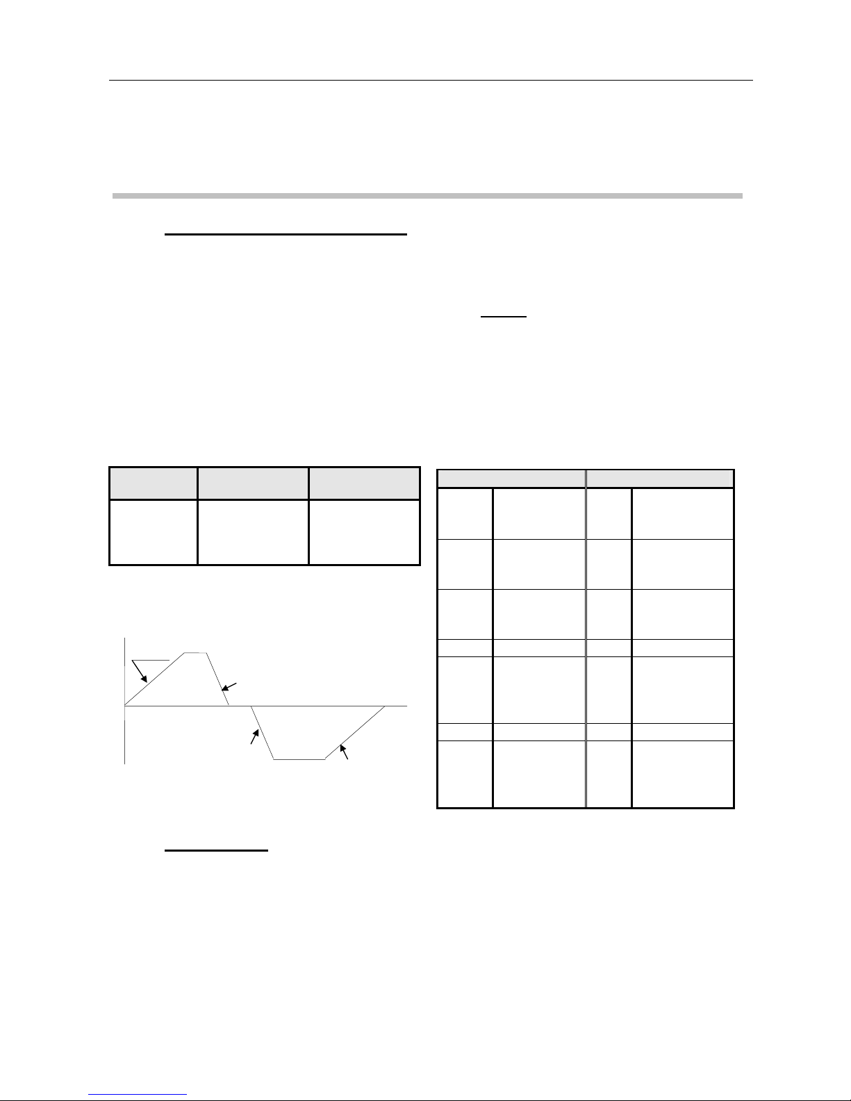
RAMP (Card RG 6601)
The ramp comes as a separate card that plugs into the RTS front panel. The card is also an
extension to terminals X1/1 to X1/9 of terminal block X1.
The ± 15 V available on RTS terminal X2 is used to power the card.
The card protrudes from the RTS by 62 mm. It is 36 mm high and 13 mm wide.
Adjustment : The ramp can be adjusted by potentiometers between 0.06 sec/Volt and 0.6 sec/Volt.
Reference Minimum time Maximum time
0 - 5V 0.3 sec 3 sec
0 - 10V 0.6 sec 6 sec
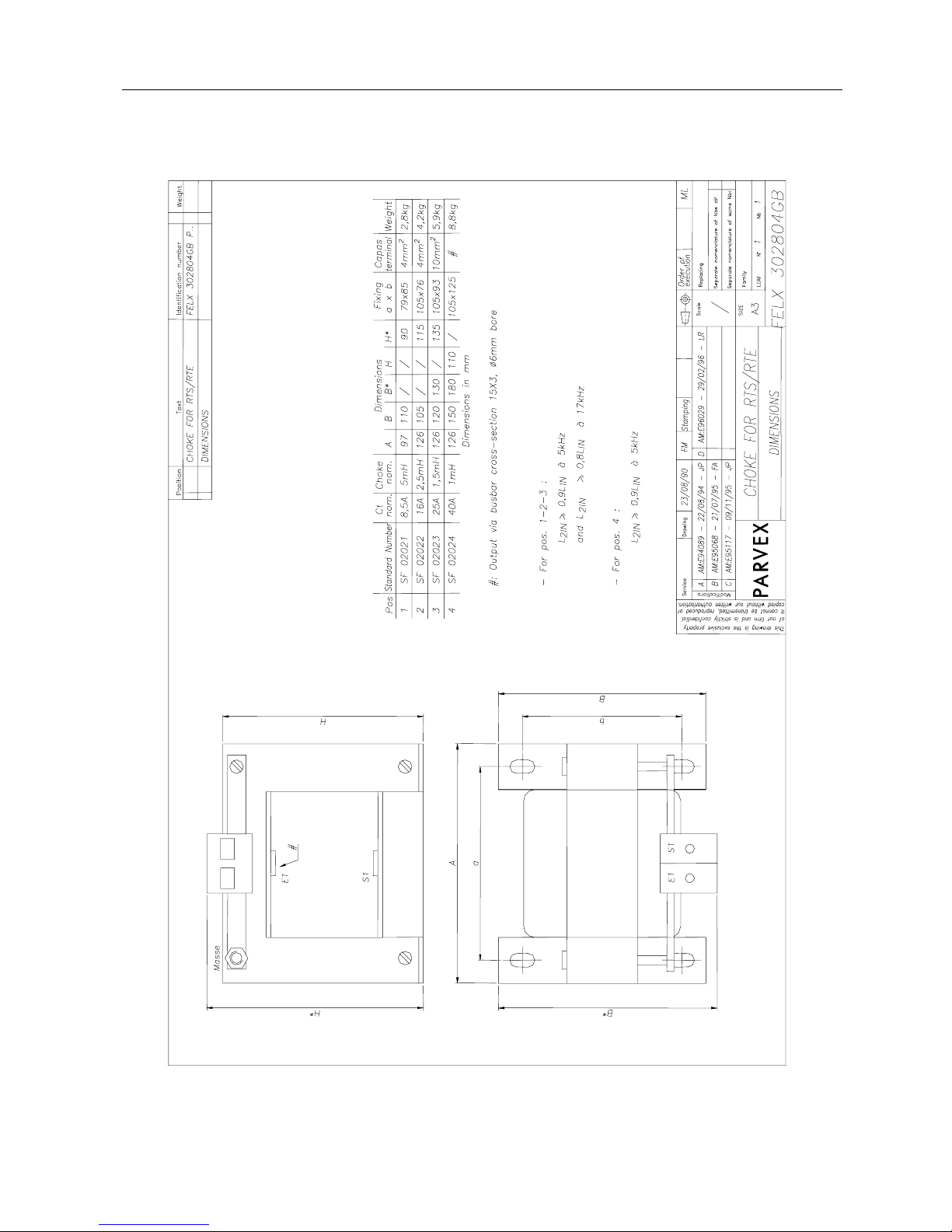
4.7.2 Extra choke
The extra choke is connected between the RTS and the servo motor, as near as possible to the
RTS. It must be used when the servo motor choke is less than the values in the table on page 7. It
should also be used when the RTS and servo motor are more than 50 m apart (or 25 m where
shielded cable is used).
X1 RG 6601 X2 RG 6601
X1/1
X1/2
Tacho inputs X2/1 +15 V (to be
connected to
X2/1)
X1/3 shielding X2/2 0V(to be
connected to
X2/2)
X1/4
X1/5
Speed
reference
inputs
X2/3 -15V(to be
connected to
X2/3)
X1/6 shielding
X1/7 Analogue
inputs
reduction of
current
X1/8 0 VA
X1/9 Analogue
Output
speed or
current value
Slopes A and B can be adjusted independently.
Slope A must equal Slope D
Slope B must equal slope C
Reference
Slope A
Slope C
Slope D
Slope B
RTS 2nd Generation SERVO AMPLIFIER
40
PVD 3487 GB 03/2004
Recommended combinations :
RTS 3/10-40M single-phase
RTS 10/20-60 single-phase SF020231 12A-2x0.25 mH
or three-phase drawing FELX 303434 (p.42).
RTS 12/24-130T three-phase
RTS 20/40-130T three-phase SF02023 25A-1.5 mH drawing FELX 302804 (p.41).
RTS 16/32-190T three-phase SF02022 16A-2.5 mH drawing FELX 302804 (p.41).
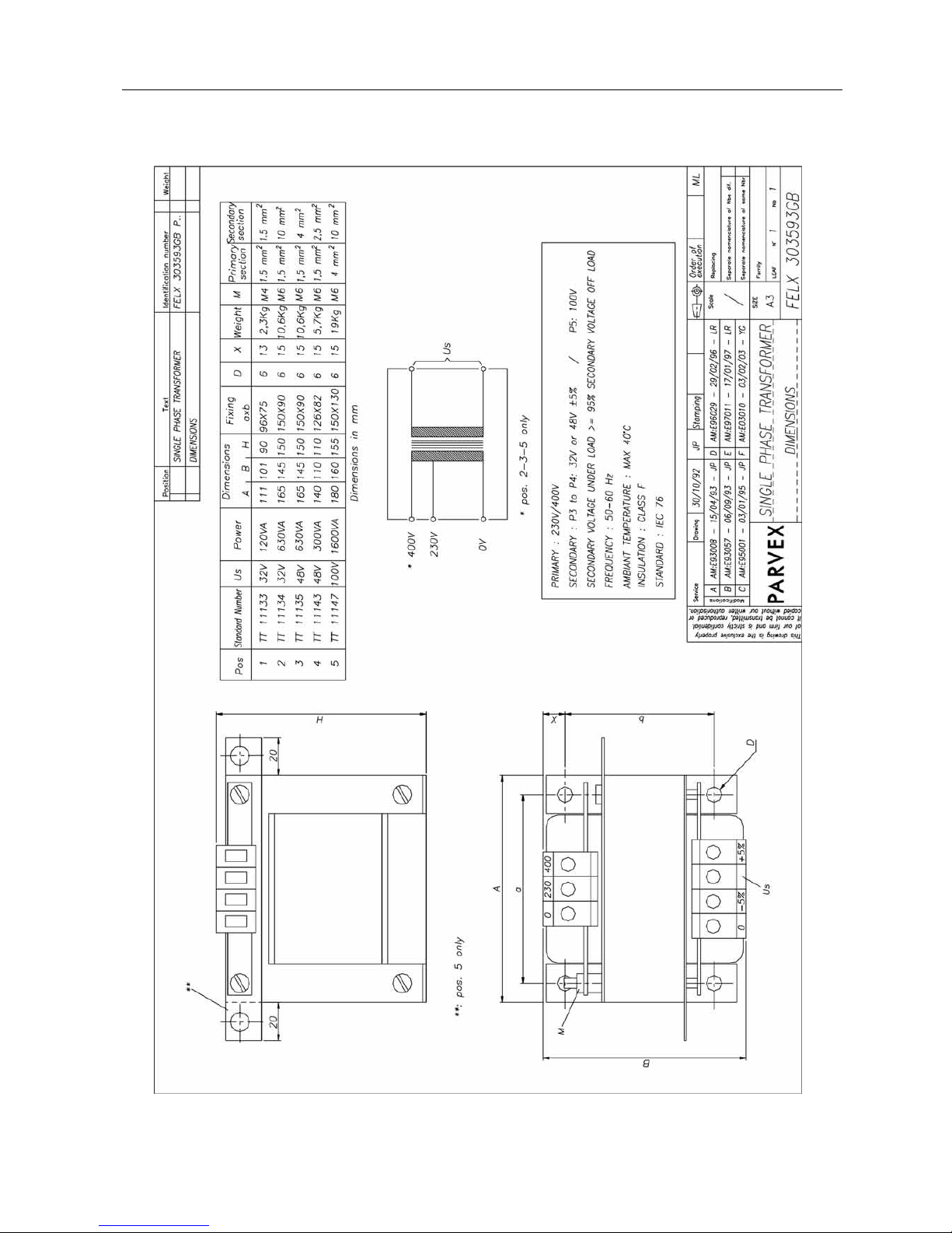
4.7.3 Transformer
General specifications
- Power supply 230/400 V - 50/60 Hz - single-phase or three-phase depending on model.
- Neutral brought out for three-phase models.
- Secondary with ± 5 % taps (except two models of drawing FELX 303740 (p.45))
- Voltage drop between load and off-load ≤ 5 %
Recommended combinations
SERVO AMPLIFIER MODEL NUMBER TRANSFORMER POWER
(VA)
CODE DRAWING P
RTS 3/10-40M single-phase
RTS 3/10-40M single-phase
RTS 10/20-60M single-phase
RTS 10/20-60T three-phase
RTS 10/20-60T three-phase
RTS 12/24-130T three-phase
RTS 12/24-130T three-phase
RTS 20/40-130T three-phase
RTS 16/32-190T three-phase
RTS 16/32-190T three-phase
RTS 16/32-190T three-phase
1
2 to 4
1
1
2 to 3
1
2
1
1
2
3
120
630
630
500
1600
1600
4000
2500
4000
6300
10000
TT 11133
TT 11134
TT 11135
TT 11136
TT 11137
TT 11139
TT 11141
TT 11140
TT 11118
TT 11119
TT 11120
FELX 303593
FELX 303593
FELX 303593
FELX 303594
FELX 303594
FELX 303740
FELX 303740
FELX 303740
FELX 302570
FELX 302570
FELX 302570
43
43
43
44
44
45
45
45
46
46
46
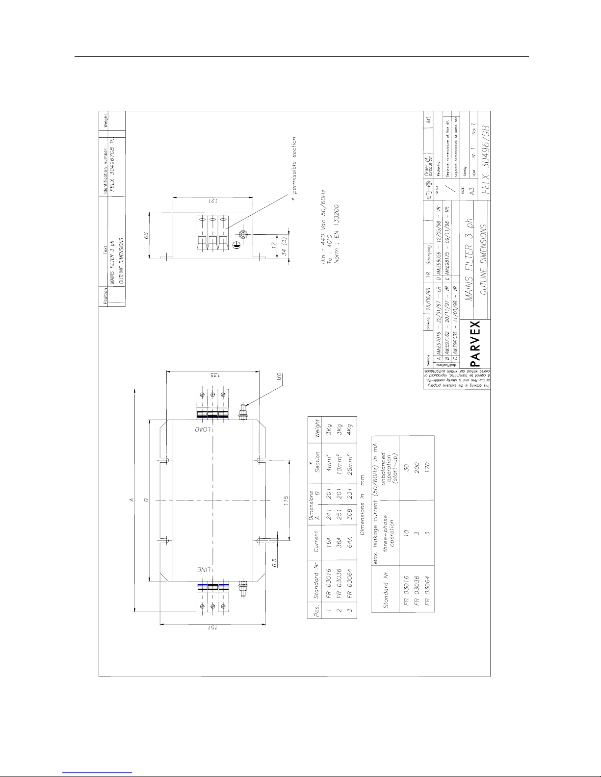
4.7.4 Mains filter
Choice of filters :
FILTER SERVOAMPLIFIER
FR13020
as per drawing PARVEXFELX305144
(p.47)
RTS 3/10-40
RTS 10/20-60
RTS 12/24-130
RTS 20/40-130
FR03016
as per drawing PARVEX FELX304967 (p.48)
RTS 16/32-190
RTS 2nd Generation SERVO AMPLIFIER
41
PVD 3487 GB 03/2004

RTS 2nd Generation SERVO AMPLIFIER
42
PVD 3487 GB 03/2004
RTS 2nd Generation SERVO AMPLIFIER
43
PVD 3487 GB 03/2004

RTS 2nd Generation SERVO AMPLIFIER
44
PVD 3487 GB 03/2004

RTS 2nd Generation SERVO AMPLIFIER
45
PVD 3487 GB 03/2004

RTS 2nd Generation SERVO AMPLIFIER
46
PVD 3487 GB 03/2004

RTS 2nd Generation SERVO AMPLIFIER
47
PVD 3487 GB 03/2004
RTS 2nd Generation SERVO AMPLIFIER
48
PVD 3487 GB 03/2004

RTS 2nd Generation SERVO AMPLIFIER
49
PVD 3487 GB 03/2004
5. LED DISPLAYS
LED displays are possible only if the supply voltage is present. The "Ready" relay, in this case,
must not be incorporated in the auto-hold of the power supply.
POWER ON
front panel
ON : energised - axis OK
OFF : no power on axis. Check wiring, fuses, internal
fuse : (FU 5x20) - 5 A (rating 3/10) - 10 A (gauge
10/20; 12/24 16/32; 20/40)
FLASHING : axis fault (see corresponding fault on side strip).
Miniature LED SIDE STRIP on side of RR 6605 card
RESET to clear faults (terminal 12)
FAULT DISPLAY
TAC
CT
MIU
MAU
dI/dT
IFT
CAUSE
- Tacho wire cut.
- Tacho wire inverted.
- Overspeed.
- Motor wire cut.
- Motor wire inverted.
Dissipater temperature too high.
LED remains on after cooling.
RESET to switch LED off.
Inadequate ac supply voltage (Min
U)
Power voltage too high (Max U).
Energy return from load too high.
Excessive ac input voltage.
Short-circuit of motor terminals
Excessive mean motor current
CORRECTION
* Check tacho wiring
* Check axis works correctly
without tacho
(selector S3 in position 0)
* Check motor wiring
* Check ventilation
* Ambient temperature too high :
fit ventilation system
* Check supply phases are
present
* Check input voltages
* Check transformer star-delta
coupling
* Check input voltages.
* Reduce axis working speed
to reduce braking energy.
* Increase servo amplifier gain.
* Check motor wiring.
* Inadequate motor choke
(Axem motor) : add series
choke.
* Reduce servo amplifier gain.
* Reduce working cycle.
NOTE : Recovery control is also displayed (REC)
RTS 2nd Generation SERVO AMPLIFIER
50
PVD 3487 GB 03/2004
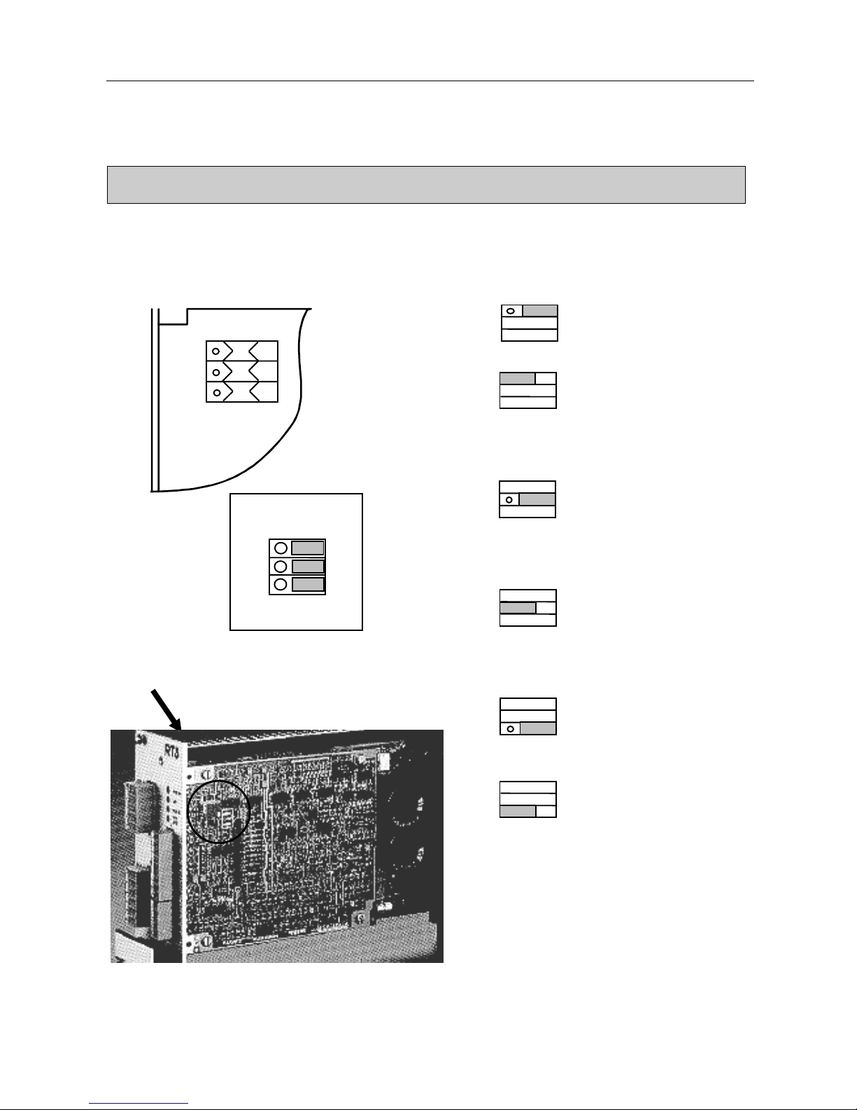
6. SERVO AMPLIFIER ADAPTATION
Selector switch positions
* Selector S1
* Position Speed control.
Speed feedback is used.
Usual case.
* Position Current control.
Speed control is unused.
X1/4-X1/5 input becomes a
current reference.
* Selector S2
* Position X1/9 output indicates current
information. ± 10 V
corresponds to pulse current.
* Position X1/9 output indicates speed
information. ± 10 V
corresponds to rated speed of
application.
* Selector S3
* Position Tacho information is used in
speed control.
* Position Speed information is
calculated from servo motor
emf.
O I
O
I
O I
O I
O I
O I
Usual position :
S1
S2
S3
O I

RTS 2nd Generation SERVO AMPLIFIER
51
PVD 3487 GB 03/2004
7. COMMISSIONING
- Check the connection of the following items :
- transformer
- relay system, especially the emergency stop
- motor and any smoothing choke
- tachometer system
- ground circuit
- Speed and current inhibited (X1/10 and X1/11 not connected),
Connect the power to the servo amplifier. The "POWER ON" LED should light up (if
not check the transformer wiring and relay system). If the "POWER ON" LED flashes,
measure the transformer secondary voltage :
RTS 10/20 - 60 Us = 48 vac : 43 vac < Usec < 53 vac
RTS 3/10 - 40 M Us = 32 vac : 29 vac < Usec < 35 vac
RTS 12/24 - 130 T Us = 100 vac : 90 vac < Usec < 110 vac
RTS 13/32 - 190 T Us = 135 vac : 122 vac < Usec < 148 vac
RTS 20/40 - 130 T Us = 100 vac : 90 vac < Usec < 110 vac
Adjust the output voltage as required with the ± 5% transformer terminals.
- With zero speed reference (X1/4 = X1/5 = 0V)
Release the servo amplifier (X1/10 and X1/11 at 0V), the motor must be under torque.
If the motor races, cut the power and check the signals from the tachometer (cut-out or
inversion) before switching on again ("TAC" fault). If the motor "growls" or "vibrates"
with possibly an "IFT" fault, reduce servo amplifier gain by turning the front panel
potentiometer anti-clockwise. If the servo amplifier had switched to fault mode
("POWER ON" flashing) use RESET (X1/12 to 0V) to clear the fault.
- Gradually increase servo amplifier reference,
and monitor motor acceleration. Check the motor rotates in the opposite direction
when the reference is reversed. If a fault arises on inversion for a 10 V reference,
adjust servo amplifier gain (see paragraph : gain adjustment).
If the fault persists, wire the power transformer secondary to the -5% terminals ("MAU"
fault on LED strip).
RTS 2nd Generation SERVO AMPLIFIER
52
PVD 3487 GB 03/2004
7.1 Speed loop rapid adjustment
* Offset adjustment
Once ambient temperature is stabilised, adjust zero speed to
the mid-position with the "SPEED OFFSET" potentiometer
on the front panel.
* Speed adjustment
The "SPEED ADJUST" potentiometer produces fine
calibration of speed for a given reference.
* Gain adjustment
By increasing gain, the servo motor becomes more rigid.
Turn the "GAIN" potentiometer clockwise until the motor is
unstable and vibrates.
Then turn the potentiometer back one or two turns. If there is
a large load on the potentiometer, the potentiometer
adjustment range may be inadequate and resistance R101
will have to be increased.
6
5
4
NON
5
4
OUI
6
RTS 1
5
4
6
NO
PLC/CN
RTS 2
5
4
6
RTS 1
5
4
6
YES
PLC/CN
RTS 2
5
4
6
Application : Potentiometer reference
..
+ 15 VDC
0V
- 15 VDC
1
2
3
5
4
6
8
Blindage
R1
R2
P
(1)
Bornier X2
Bornier X1
(1) Terminal 4 may be connected to terminal 8
Example
: ± 10 V
P = 10 kΩ linear
potentiometer
R1 and R2 = 2,2 kΩ, 1/2 W resistor
Shielding not connected at numerical control end
The connecting cable by shielded twisted pair for the tacho and reference is available as an option.
Inputs not connected
Terminal block X1
Terminal block X2

RTS 2nd Generation SERVO AMPLIFIER
53
PVD 3487 GB 03/2004
7.2 Complete speed loop adjustment
Systematically applicable when J charge ≥ 10 J motors
Caution As servo amplifiers are factory set based on
parametersprovided by the customer, this setting does
not usuallyrequire adjustment.
Before adjusting the speed loop, all the adjustable
parameters must be fixed (current limits, speed scale
setting, speed limits). Adjusting the speed scale setting
alters loop gain and means readjustments are required.
Equipment required
- Storage oscilloscope (digital if possible), easy to trip.
- Manual speed reference generator (battery box) or low
frequency generator with series capacitor to produce
zero mean speed (out and return about a position).
- Decade box for capacitor and resistor adjustment.
Reference battery box, with oscillator for automatic
control is available as an option.
Method
FIG 1
Adjust the gain potentiometer to the centre (so gain may
be varied up or down after adjustment).
Fit a large integration capacitor C101 - 10µF or strap.
Adjust proportional gain starting by R101 = 10 kΩ.
Increase R101 until 10% overshoot on speed reference
increment. Always use small speed reference increments
(e.g. ± 100 rpm or less) so the system remains linear. For
large increments, current limitation (= torque limitation)
masks the real situation and reduces overshoot.
The adjustment obtained with high speed increments
would be incorrect.
In many cases, it is not possible to increase gain to
produce overshoot especially for high inertia systems.
< 100 Hz
a
b
c
Temps
Vitesse prise entre
mesure N et 0V ana. dépassement : + 10 %
-
+
batterie
9 V
INVERSEUR
10K
Réf. E -
Réf. E +
15
14
Servoamplificateur
Gain
R108
R101
C103
C101
FIG 1 : a, b, c - graphs obtained with
increasing R101 values
Speed amp
INVERTER
10 K
1-5
Ref. E1-
Speed recorded
between N measurement
and 0 V analo
g
ue
overshoot : +10%
9 V
battery
Ref. E1+
1-
4
Time

RTS 2nd Generation SERVO AMPLIFIER
54
PVD 3487 GB 03/2004
FIG 2
In some cases, gain limitation is due to resonance: the
motor starts to whistle or vibrate at high frequencies (>
100 Hz). A -1 filter must be included at a frequency 3 to 4
times lower than the oscillation so the gain can be
increased by the same ratio. This can be done by
connecting a C103 capacitor in parallel with the R101
proportional gain resistor, and increasing the capacitor
until the whistling stops (usually several tens of nF) and
then continuing to increase gain while monitoring
overshoot and torque ripple. The C103 10 nF capacitor is
ready fitted as standard in parallel with the R101 gain
resistor.
FIG 3
When the gain is set, the C101 integration capacitor must
be reduced to produce 15 - 20% overshoot (still for small
speed increments).
100 à 300 Hz
a
b
c
Temps
a
b
c
Temps
Dépassement 20 %
Vitesse
FIG 3 : a, b, c - graphs obtained with
decreasing C101 values
FIG. 2 : a, b, c, - graphs obtained with
increasing C103 values
100 - 300 Hz
Time
Speed
20% overshoot
Time
RTS 2nd Generation SERVO AMPLIFIER
55
PVD 3487 GB 03/2004
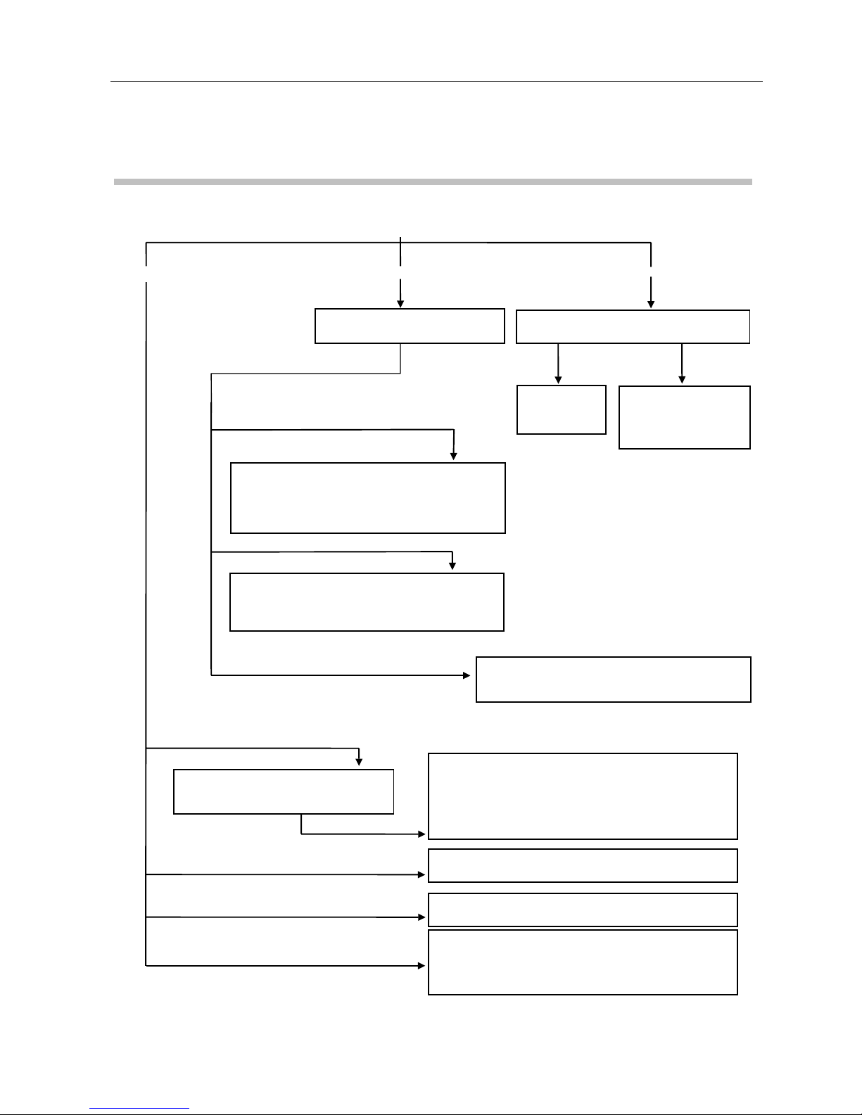
7.3 Diagnostic helpI
ENERGISING
Check :
• terminals X1/10 and X1/11 must be connected to 0V
• selector S1 must be in correct position
• reference voltage is present
"POWER ON" flashes
« POWER ON » on
"POWER ON" of
f
Check which LED on side of
card
Measure voltage at terminals U, V, W
Check fuse
F1 (gauge 5 x
20
)
Check fuses, main
switch and
transformer
connections
Voltage
No
Motor races and "TAC" LED lights up
Check tachometric dynamo wiring, invert
tacho wires if fault arises during first time use.
Motor under current control: selector S1 must
be changed.
Check motor wiring and fuses. If the dI/dT
LED is on, check the motor is not shortcircuited and there is no ground fault.
Motor fails to rotate
Check the ventilation system is working correctly.
A
mbient temperature of the electrical cabinet must
be less than 40°C.
"CT" (temperature) LED is on
The motor is unstable and vibrates
Reduce gain using the front panel
potentiometer : turn anti clockwise
Check the motor and servo amplifier are grounded
(mandatory).
Check the speed reference is stable (with oscilloscope)
and ±15 V voltages if necessary.
Check the customisation components correspond to the
motor.
No effect
Adjust zero speed with the "SPEED OFFSET"
p
otentiometer
Adjust speed with "SPEED OFFSET" potentiometer
Motor drifts
Incorrect speed
Motor fails to rotate

RTS 2nd Generation SERVO AMPLIFIER
56
PVD 3487 GB 03/2004
7.4 Calibration
The components below are stud mounted and used to calibrate the servo amplifier for the
corresponding motor. Calibration is done at the manufacturer's facility before delivery and these
components should not be modified.
CAUTION : Servo amplifiers are factory set and the information
in sections 7.4.1 - 7.4.11 are for reference only.

RTS 2nd Generation SERVO AMPLIFIER
57
PVD 3487 GB 03/2004
TACHOMETER SYSTEM EMF
RATED SPEED
RTS 2nd Generation SERVO AMPLIFIER
58
PVD 3487 GB 03/2004
Symbols used
Nn = rated speed of application for 10 V reference speed
Ilim = maximum pulse current of motor
Imax = maximum pulse current of servo amplifier
In = maximum rated current of motor
Ket = gradient of tachometric generator in V per thousands of rpm
Ke = back electromotive force of motor in volts per rpm
r = resistance of motor and its supply circuitry in ohms
L = inductance of motor in mHenrys
Ub = bus voltage in volts (1.35 x Vin AC)
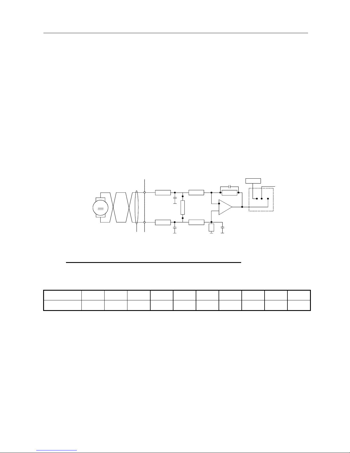
T
Tachy
+ X1/1
- X1/2
100 K
100 K
2.2 nF
R 104
100 K
100 K
2.2 nF 200 K 1nF
200 K
1nF
U - RI
O
I
S3
Sélection TACH
Y
ou U - RI
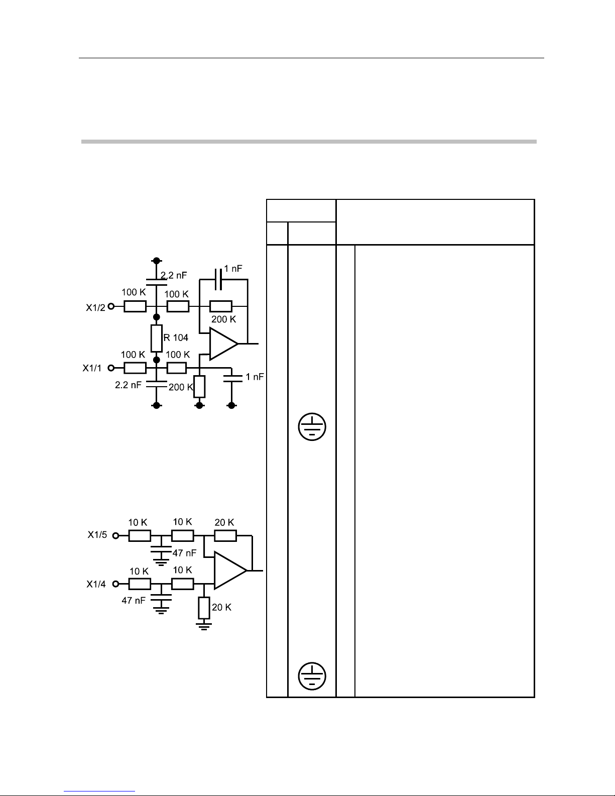
7.4.1 Tachometric generator voltage calibration (R104)
Resistor R104 is used to adapt the tachometric generator gradient to that of the servo amplifier
(2V/1000 rpm).
Ket 2 3 4 5 6 8 10 12 15 20
R 104 (kΩ) ∞
200 100 68 51 33 24 20 15 11
Do not exceed 100V on the tachometer input.
For a gradient of 1 V / 1000 rpm, short-circuit the solder tags Y1 and Y2 with R104 =
∞.
Standard tachometric generator values are :
3 V at 1 000 rpm e.g. TBN 103
6 V at 1 000 rpm e.g. TBN 206
20 V at 1 000 rpm e.g. TBN 420
These values are plated of tachometric generator. e.g.
Ke : 6 mVrpm or 6 V at 1000 rpm
TACHO selection
or U-RI
Tacho
RTS 2nd Generation SERVO AMPLIFIER
59
PVD 3487 GB 03/2004
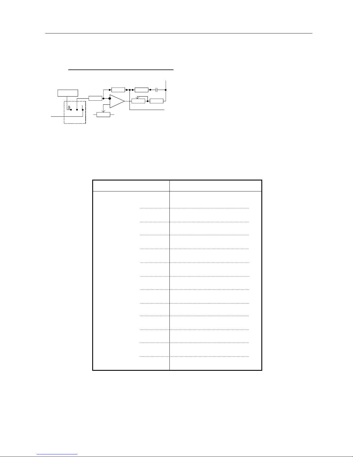
7.4.2 Rated speed selection (R105)
Resistor R105 calibrates the useful speed of the
application. For a speed reference of ± 10 V, the
speed corresponding in rpm to the servo motor will
be determined by R105 according to the table
below.
Calibration accuracy supposes that R104
calibration value of the tacho is correctly set.
The "SPEED ADJUST" potentiometer on the front
panel allows easy fine adjustment of speed.
Turning it clockwise increases speed for a given
reference.
Speed Nn (rpm)
R 105 (kΩ)
700
770
869
950
1055
1200
1280
1400
1590
1650
1750
1800
1920
2100
2330
2600
2820
3100
3420
3700
4040
4400
4900
5200
274
221
182
150
121
110
100
82.5
68.1
56.2
47.5
39.2
The equipment may be adapted for speeds lower than those shown above but this hinders servo
amplifier performance with regard to drift and gain. The maximum value not to be exceeded for
R105 is 4.75 MΩ.
U - RI
S3
TACHO selection or U - RI
Offset
R105
R102
C102
10 K
Fine speed adjustment
39 K

RTS 2nd Generation SERVO AMPLIFIER
60
PVD 3487 GB 03/2004
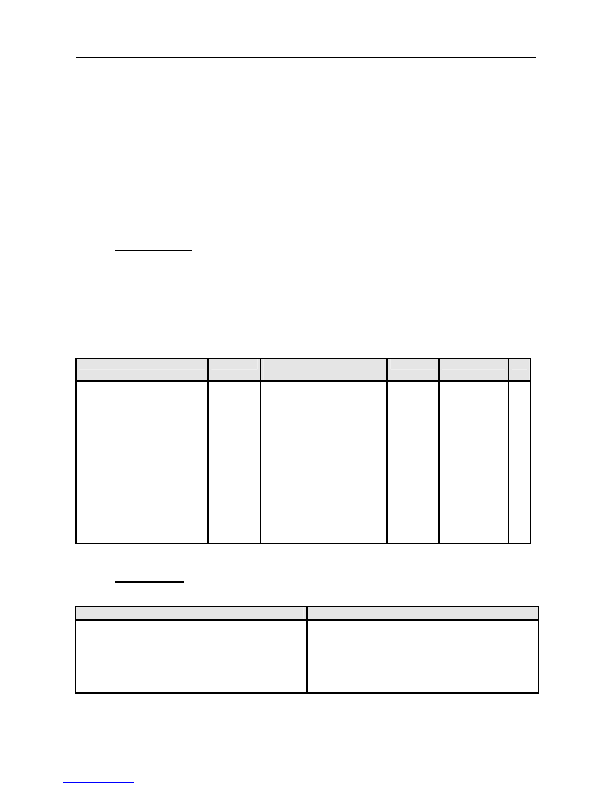
7.4.3 Pulse current adjustment (R113)
R113 modifies the maximum current authorised by the servo amplifier.
The standard pulse current is twice the value of the permanent current. It may be set either
internally by using R113 or by using current reduction input X1/7 "Ired".
The table below shows the value of resistor R113 in kΩ versus the percentage of maximum
current.
% of maximum
current
10 20 30 40 50 60 70 80 90
R113 (kΩ)
0.392 0.825 1.5 2.21 3.32 4.75 7.5 12.1 33.2
7.4.4 Current limitation by external resistance or external voltage
(terminal block X1)
7.4.4.1 By external resistance
The table below shows the external resistor value
in kΩ versus the percentage of maximum current.
Voltage control between terminals 7 and 8 is also
possible. In this case, the current is linear with
10 V = I max.
% of maximum
current
10 20 30 40 50 60 70 80 90
Rext (kΩ)
3.32 6.81 10 15 22.1 27.4 39.2 47.5 56.2
7.4.4.2 By external voltage
Voltage control between terminals 7 and 8 is also possible. In this case, the current is linear with
10 V = I max.
47 k
+ 15 V
20 K
I Red
R ex.
870V A

RTS 2nd Generation SERVO AMPLIFIER
61
PVD 3487 GB 03/2004
7.4.5 Time constant adjustment I = f(t) (R109)
The system time constant is factory set so the
servo amplifier accepts maximum current for one
second, starting from I = 0. After one second the
servo amplifier switches automatically to safety
mode.
Standard resistor R109 is 562 kΩ for a maximum
current lasting 1 second. For a maximum current
lasting 2 seconds, resistor R109 must be 1210 kΩ.
7.4.6 Adjustment of function I = f(t) (R103)
Function I = f(t) is designed to protect the servo amplifier and servo motor if the mean current
required exceeds the rated current.
Resistor R103 is used to adjust the tripping limit authorised by the servo amplifier.
RTS 3/10 - 40
% of rated
current
50 60 70 80 90 100
R103 (kΩ)
1.82 2.74 3.92 4.75 6.81 8.25
RTS 10/20 - 60
12/24 - 130
12/24 - 24/48
16/32 - 190
20/40 - 130
% of rated
current
20 30 40 50 60 70 80 90
R103 (kΩ)
1,5 2,21 3,32 4,99 7,5 12,1 20 43,2
AUTION : For safety reasons the values of resistors R109 and R103 must not
be altered without authorisation from PARVEX - Warranty may be
affected.
4.7 M
R109
2 µF
10 K
+ 15 V
20 K
R 103
RTS 2nd Generation SERVO AMPLIFIER
62
PVD 3487 GB 03/2004
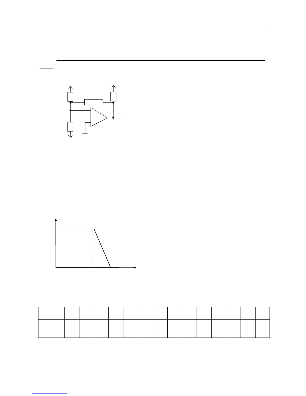
7.4.7 Adjustment of current limitation curve versus speed I F(n) (R131 -
132)
Resistor R131 is used to select the zero current point on the speed current diagram.
Resistor R132 determines the speed beyond which pulse current (selected by R113) begins
to decrease linearly with speed.
When function I = F(n) is not required :
R131 = 10 KΩ
R132 = 100 KΩ
Nr : speed in thousands of rpm above which
current decreases
Ns : speed in thousands of rpm at which current is
zero
R131 values
Ns
(rpm)
500 1000 1500 2000 2500 3000 3500 4000 4500 5000 5500 6000 6500 7000
R 131
(kΩ)
16.2
82.5
56.2
39.2
33.3
27.4
22.1
20
18.2
16.2
15
13.7
12.1
12.1
+ 15 V
10 K
R 132
- 15 V
R 131
Réduction
de I
I
Ilim
Nr Ns N
Current
reduction
RTS 2nd Generation SERVO AMPLIFIER
63
PVD 3487 GB 03/2004
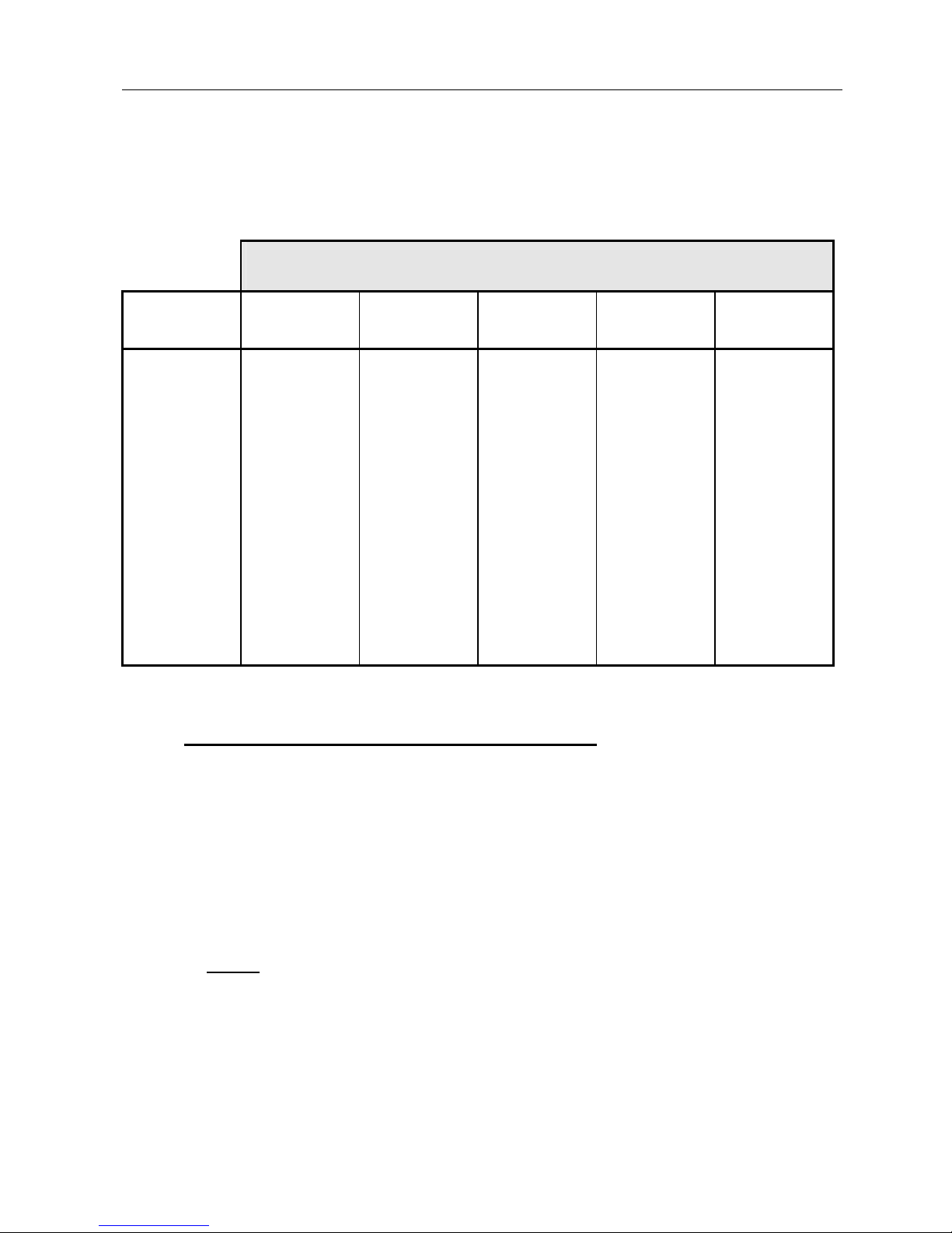
R132 values
% of maximum current
Ns - Nr
20
40
60
80
100
500
1000
1500
2000
2500
3000
3500
4000
27.4 k
Ω
12.1 k
Ω
8.25 k
Ω
6.81 k
Ω
5.62 k
Ω
4.75 k
Ω
3.32 k
Ω
3.32 k
Ω
47.5 k
Ω
22.1 k
Ω
16.2 k
Ω
12.1 k
Ω
10 k
Ω
6.82 k
Ω
6.82 k
Ω
5.62 k
Ω
100 k
Ω
33.2 k
Ω
22.1 k
Ω
18.2 k
Ω
15 k
Ω
10 k
Ω
10 k
Ω
8.25 k
Ω
82.5 k
Ω
47.5 k
Ω
33.2 k
Ω
22.1 k
Ω
18.2 k
Ω
15 k
Ω
13.7 k
Ω
12.1 k
Ω
121 k
Ω
56.2 k
Ω
39.2 k
Ω
27.4 k
Ω
22.1 k
Ω
18.2 k
Ω
16.2 k
Ω
15 k
Ω
7.4.8 Calibration of function U - RI (R133 - R134)
This adaptation is necessary even when operating with a tachogenerator to ensure tacho safety:
speed signals from "U - RI" and from the tacho are compared constantly and must be of the
same order of magnitude.
EMF per 1000 rpm : The electromotive force constant KE indicates the voltage measured on the
armature for an off-load speed of 1000 rpm, at 25°C. Under load, for agiven
voltage, motor speed will be:
I = current between terminals in Amps
R = armature resistance in Ohms
U = voltage across terminals in Volts
K
E = EMF constant in Volts per 1000 rpm
N = U - (RI)
x 1000
K
E
RTS 2nd Generation SERVO AMPLIFIER
64
PVD 3487 GB 03/2004
To calculate motor speed, coefficients R and KE must be calibrated by the resistor values
below :
R 133 [kΩ] R 134 [kΩ]
RTS 3/10 - 40
RTS 10/20 - 60
RTS 12/24 - 130
RTS 12/24 - 24 B 1)
RTS 12/24 - 48 B
RTS 16/32 - 190
RTS 20/40 - 130
180/ K
E
260/ KE
540/ K
E
96/ K
E
192/ K
E
760/ K
E
540/ K
E
40 R
60 R
32 R
154 R
77 R
32 R
64 R
e.g. RX 120 L servo motor with RTS 3/10-40
K
E = 11.5 V/1000 rpm R 133 = 15 kΩ
R = 2.5 Ω R 134 = 100 kΩ
1) with RR6606C : R133(kΩ)=192/ K
E ; R134(kΩ)=77R
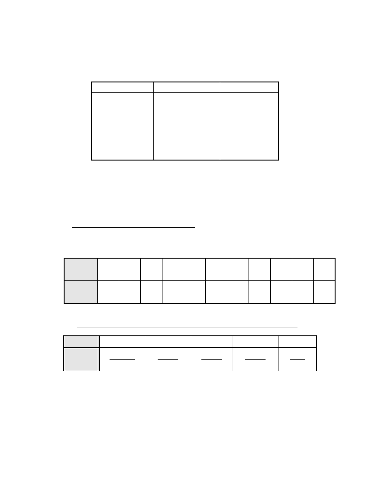
7.4.9 Tripping limit calibration (R135)
Resistor R135 determines the tripping limit of maximum speed for tachometric servo control and
U - RI operation.
Nn
(rpm)
1000 1500 2000 2500 3000 3500 4000 4500 5000 5500 6000
R 135
(kΩ)
1.5
2.74
3.92
4.75
6.81
8.25
12.1
15
22.1
27.4
39.2
7.4.10 Current loop gain adaptation to motor inductance (R136)
RTS 3/10 10/20 12/24 16/32 20/40
R136
kΩ
Ub
L
3
10.5,2
Ub
L
3
10.5
Ub
L
3
10.6
Ub
L
3
10.8
Ub
L
4
10
Ub : drive bus direct voltage (Volts)
L : motor inductance and any additional inductance (mH)
When selecting R136 take the value immediately below in the following range and multiples
thereof::
10 - 12 - 15 - 18 - 22 - 27 - 33 - 39 - 47 - 56 - 68 - 75 - 82 - 100

RTS 2nd Generation SERVO AMPLIFIER
65
PVD 3487 GB 03/2004
7.4.11 dc voltage calibration (RB)
Resistor RB is used to adapt limit values: MAX U, MIN U, tripping of supply voltage recovery.
The standard values are as follows :
SERVO AMPLIFIER
MODEL
Input
voltage
VAC (1)
DC
voltage
Max
voltage
Min
voltage
Dissipation resistance
On limit Off limit
V V
RB
kΩ
RTS 3/10 - 40
RTS 10/20 - 60
RTS 12/24 - 130
20/40 - 130
RTS 12/24 - 48
RTS 12/24 - 24
RTS 16/32 - 190
32
48
100
48
24
135
43
65
135
48
24
190
57
86
179
64
34
240
27
40
83
30
16
112
53
79
164
-
-
221
50
75
156
-
-
210
200
∞
∞
∞
100
∞
(1) Remark : The RTS servo amplifier may be used with supply voltages different from
the standard values.
e.g. RTS 10/20-40 with 32 V supply
RTS 16/32-140 with 110 V supply
Please ask for details.
 Loading...