

Page 1
690+
690+
Quick Start
Quick Start
Associated Literature
690+ Installation Manual HA465492Uxxx
690+ Software Manual HA465038Uxxx
VIEW LEVELS
There are three View Levels to the menu
Operator – A very simple level . No setup allowed
Basic – Default mode of the menu. Allows quick
setup, save, restore and full diagnostics
Advanced - Allows full access to the
comprehensive set of function blocks in the Setup
menu and more choices in the System menu to
choose Language defaults and more
View Levels may be selected from the Quick
Setup menu, under View Level
MACROS
The 690+ comes packaged with several Ma cros,
which are preconfigured schemes. Current macros
include
Basic speed control - Load this to return to factory
default parameters
Raise/Lower – Pushbutton ramp using increase/
decrease inputs
PID – Provides closed loop process control
SPW – Speed program winder (closed loop trim)
PRESET SPEEDS – Provides 8 preset speeds
To load a Macro, go to SYSTEM\RESTORE
CONFIG and select the macro you wish to load
frames C
frames C--FF
1515--150 HP
150 HP
7.5
7.5--
90 kW
90 kW
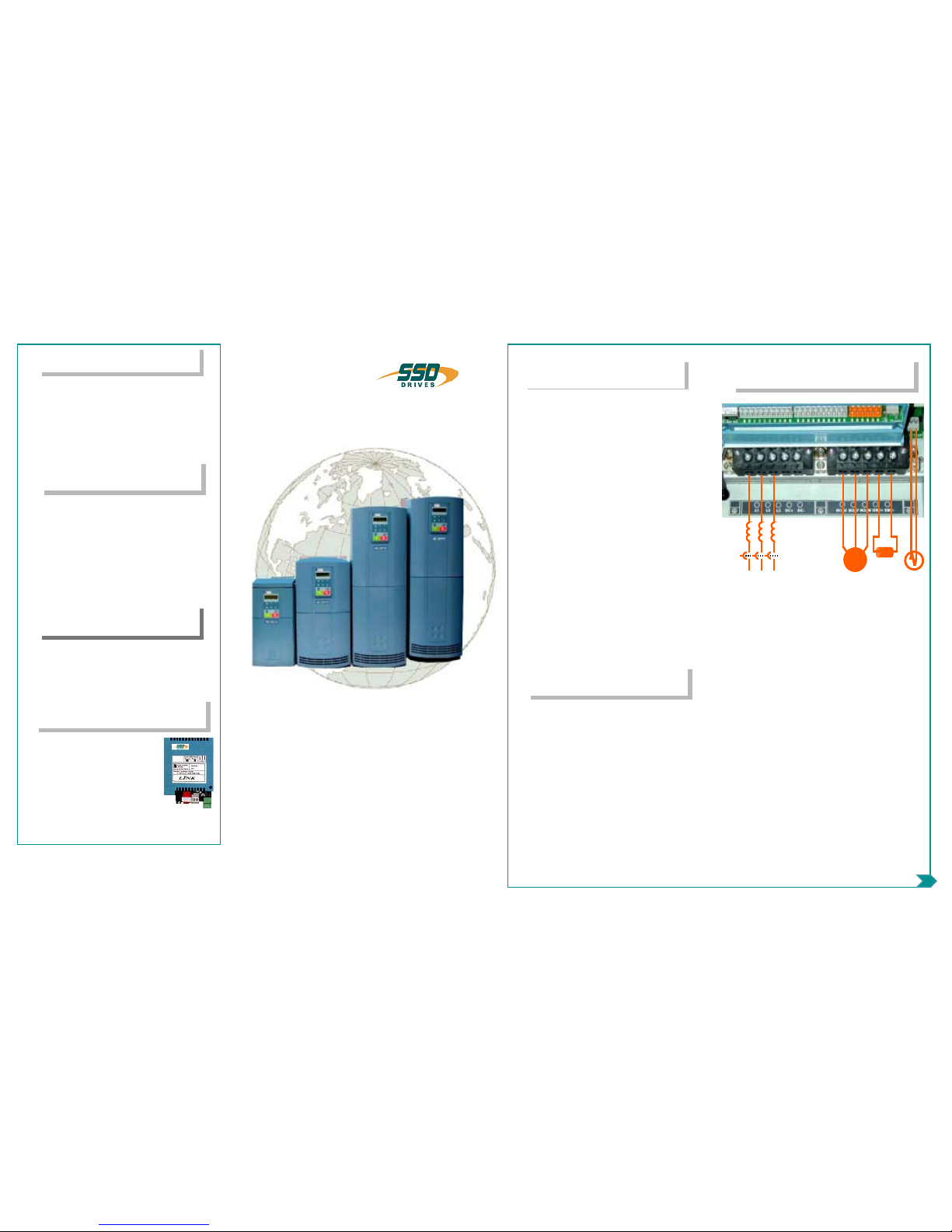
POWER CONNEC TIONS
• 3-phase supply to L1, L2, L3.
• Motor connections to M1, M2, M3
• Brake resistor between DBR+, DBR-
• Motor thermistor to MOT TEMP
• Common Bus to DC+, DC-
• Frame F only: 115/230V fan supply to
L,N
Ground lugs have been provided for each
of the power circuits. Follow proper grounding and shielding methods as described in
chapter 3 of the Installation Manual,
If the stop time is expected to be less than
the natural coasting time of the load, order
the factory mounted braking module option
on frames D through F. Frame C has a
built-in braking module. Connect the braking resistor across DBR+ and DBR-.
Flux Vector
Sensorless Vector
Volts /He rtz
BEFORE YOU STAR T
This document covers the steps necessary
for a basic start up of the 690+ drive. Drive
start ups should be performed by qualified
electrical technicians who are familiar with
AC drives and their applications. For detailed installation and safety information
refer to the Installation Manual. For advanced features and applications, refer to
the Software Manual.
Ensure that all local electric codes are met
while installing the drive. Check that all live
parts are covered to protect against electric
shock and that unexpected rotation of the
motor will not result in bodily harm or injury.
This document expects that the drive is
already installed in its intended location
and that all relevant installation procedures
have been followed. Please ensure that the
drive has adequate ventilation so that ambient temperature does not exceed 45°C
(112°F) under normal operating conditions.
To access the terminals, loosen the two
retaining screws at the bottom of the drive,
pull up gently on the terminal cover and
slide it off.
CONTROL MODES
The 690+ supports 3 different control
modes
Volts/Hertz mode – Most basic open loop
operation, used in fans/pumps and multimotor applications. No options needed
Sensorless Vector mode – Tight speed
regulation with good transient torque
capability, without the need for speed
feedback. No options needed
Flux Vector mode – Precise flux vector
control with full torque down to zero speed
and improved dynamic performance.
Optional Speed Feedback Technology
Card required on the drive and an encoder
on the motor
TECHNOLOGY BOXE S
The 6055 series of Technology
boxes is available to communicate with protocols such as DeviceNet, PROFIbus, ModBus,
RS485 serial comms, CAN bus
and LON works. Any of these
may be plugged into the right-side
techbox port. Securely snap into
place, then tighten the ground
screw
Networking a standard 690+ to
LINK is done
with the LINK techbox. This has a built-in processor that can be configured using DSD, the
INTERNAL LINKS
Under SETUP\LINKS, you may connect and disconnect internal block diagram connections, to use
special functions like PID, winder blocks, diameter
block, etc., and to tag analog and digital I/O to selected points inside the drive to suit your application needs. Specify sources and destinations to 50
internal links.
The power terminals shown are for frame D.
Although other frames may vary slightly in
appearance, their terminal designations and
functionality are identical
Visit us at www.SSDdrives.com
USA: (704) 588-3246 UK: +44 (0)1903 737000
HA470631U200 Issue 5
3 phase power
3 phase power
thermistor
thermistor
~
~
motor
motor
braking
braking
resistor
resistor
3 phase power
3 phase power
thermistor
thermistor
~
~
motor
motor
braking
braking
resistor
resistor
*HA470631U200*
Page 2
P
P
P
OWER
OWER
OWER
O
O
O
N
N
N
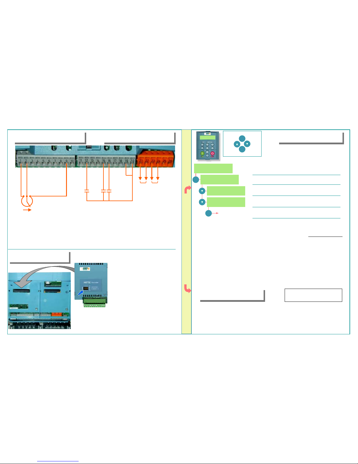
REFERENCE SEQUENCING
• Speed potentiometer across 1(low), 9(high),
2(wiper) OR
• External 2-wire speed reference between
1(-) and 2(+)
• Jumper 19 and 20 if no external trip contact
• Start contact between 12 and 20
• Jog contact between 16 and 20
• Reverse Direction contact between 15 and 20
• Health volt-free contacts between 21 and 22
• Running volt-free contacts between 23 and 24
CALIBRATION
AC MOTOR DRIVE
7.5KW 400V 1.3
DIAGNOSTICS
Menu at Level 1
QUICK SETUP
Menu at Level 1
M
OPERATOR
Menu at Level 1
M
DOWN arrow to get to the DIAGNOSTICS menu
Press the M key to get to OPERATOR LEVEL
DOWN arrow to get to the QUICK SETUP menu
Press M to enter QUICK SETUP and set parameters relevant
to the operating mode of the drive by scrolling UP or DOWN
All calibration is done in software, through
the keypad
The 690+ can also be calibrated using the programming tool software
M
E
ESCAPE ONE LEVEL
ENTER MENU
SCROLL
UP
SCROLL
DOWN
The following is a list of the relevant parameters that you may need to check before starting the
drive. Several of these may not need adjustment if you are running a standard 60Hz, 460V 1800
RPM induction motor
V/Hz SV Vector
1 Control Mode Select the intended operating mode x x x
2 Max Speed Set max speed in RPM x x x
3 Min Speed Set min speed in % x x x
4 V/Hz shape Choose fan only for square curve x
5 Motor Current Motor full load current x x x
6 Motor Base Freq Motor nameplate frequency x x x
7 Motor Voltage Motor nameplate voltage x x x
8 Nameplate RPM Motor nameplate RPM x x x
9 Motor Poles for 1800rpm=4, for 1200rpm=6 x x x
10 Encoder Supply set between 5-15V to match encoder x
11 Encoder Lines Pulses per Revolution of encoder x
12 Encoder Invert Changes polarity of encoder feedback x
13 Autotune Enable Drive will Autotune if started x x
AUTOTUNE
• In the QUICK SETUP menu, set AUTOTUNE ENABLE to TRUE
• MAX SPEED should be greater than NAMEPLATE RPM for a successful autotune
• On the keypad press L/R for LOCAL mode
• Ensure that the motor is uncoupled and free to rotate without causing problems
• Press RUN. Drive will begin autotuning, The drive will stop without errors if autotune is successful
• Go to SYSTEM\SAVE CONFIG\APPLICATION and UP arrow to save your settings
START
START
JOG
JOG
REV DIR
REV DIR
HEALTH
HEALTH
N.O. CONTACT
N.O. CONTACT
RUNNING N.O. CONTACT
RUNNING N.O. CONTACT
SPEED
SPEED
REFERENCE
REFERENCE
21
21
22
22
23
23
24
24
25
25
26
26
EXT. TRIP
EXT. TRIP
+ 24 VDC
+ 24 VDC
• The 6054 Encoder Techbox is required
only for closed loop Flux Vector Control
• Plug the 6054 into the left hand techbox
port, as shown. Securely snap into place,
then tighten the ground screw
• DIP switches 1,2,3,4 (blue arrow) set the
threshold voltage of the encoder signals. Set
all switches to ON (up position) for complementary encoder signals
• Encoder connections to terminal block are:
1 (FUTURE) Health pulse H
2 (FUTURE) Health pulse H complemen t
3 Channel A
4 Channel A complement
5 Channel B
6 Channel B complement
7 Marker pulse M
8 Marker pulse M complement
9 Encoder Supply positive (5–15VDC)
10 Encoder Supply negative (0V)
11 Ground / Shield
SPEED FEEDBACK
Note
In V/Hz mode, Autotune is not
necessary and will not activate
This is the power-up welcome screen. If a different screen
appears, press E a few times to return to the this screen
 Loading...