

Page 1
ENGINEERING BETTER BEER
eController Product Guide
Page 2
OVERVIEW
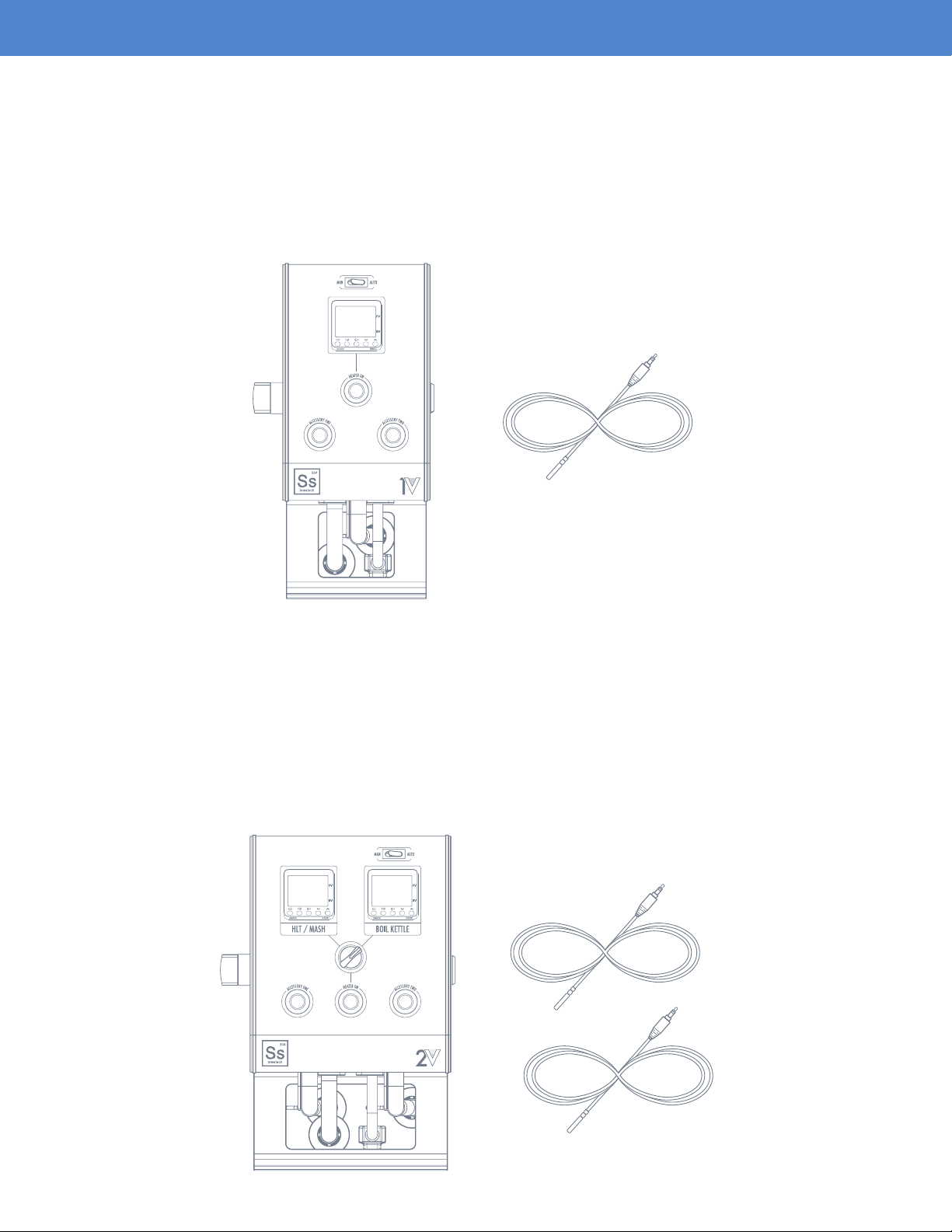
eCONTROLLER 1V
The eController 1V is designed to be used with a brew-in-a-bag system (BIAB), but can also be useful
for someone who prefers modularity within their multi-vessel system. It can easily replace an existing
gas-red HLT or boil kettle in an existing 3 vessel brewing system. The 1V controller is designed to
operate one element, and is compatible with our line of 10 and 20 gallon eKettles. A 30A dedicated
GFCI protected circuit is required.
(1) Thermoprobe
eCONTROLLER 2V
The eController 2V is designed to be used as part of a 3 vessel, single infusion mash system. The
controller pairs perfectly with our line of insulated InfuSsion Mash Tuns, alongside a pair of temperature
controlled eKettles for the HLT (hot liquor tank) and boil kettle. The 2V controller can operate 2 elements
in total, albeit one at a time, and is compatible with our line of 10 and 20 gallon eKettles. Since only
one element can be operated at a time, the 2V controller retains the same 30A GFCI protected circuit
power requirement as the 1V.
(2) Thermoprobes
Page 2
Page 3

INTRODUCTION
Designing every piece of our electric brewing equipment from scratch has enabled us to introduce
a new level of process control, exibility, and performance. Every detail has been carefully thought
through and rened.
Every component of our new eControllers was designed to enhance the eBrewing experience.
The custom extruded 6061 aircraft-grade aluminum housing is CNC machined, then coated in a
durable black anodized nish. This approach allowed us to keep the system compact, portable
and functional. The housing includes an integrated carry handle for easy setup and take down,
a T-slot for alternative mounting options along with a heatsink to keep the internal electrical
components cool.
The eController is driven by a PID controller, which doesn’t rely on high speed switching to module
heat. Voltage is modulated through an internal SSVR, which means element wattage will be directly
proportional to the set point on the eController. A rocker switch located just above the PID controller
allows the user to operate the controller in manual or automatic modes.
In manual mode, the proportional output can be ne-tuned on a scale of 0-100% of total element output,
which is ideal for dialing in a perfect rolling boil. Alternatively, in automatic mode, the PID algorithm
manages the proportional output relative to process temperature. To hold a steady HLT or mash temp
for instance. The eController quickly nds equilibrium with environmental heat loss characteristics, and
can maintain a high degree of accuracy during each brewing process.
The heater button allows the user to turn the element on or off without having to shut off the main
power or adjust the PID output setting. This is especially helpful if a boil-over occurs. This feature also
allows the eController to be used to monitor a process temperature, such as during runoff or in the latter
stages of the sparge process without the risk of dry ring the element. Lastly, the eController features
two accessory outputs, which would commonly be used for pumps, but could also be used for lighting
or even a phone charger.
Connectivity was an important consideration for our eControllers, we wanted the exibility and familiarity
of a plug that could be adapted to an existing customer supplied kettle or element, and the reliability
of a UL approved connector type. For 240VAC main power and element connectors, we chose on the
common NEMA L6-30 standard, which is a 3-wire twist-lock plug type, capable of carrying 30 amps
of current. For the accessory connections, we settled on using a NEMA 5-15 standard, which is just
a standard residential 120 VAC outlet. Finally, for the PT100 temperature probes we opted for the 3.5
mm mini jack connector standard, commonly used for headphones, which is both durable and easy
to use.
Page 3
Page 4
ASSEMBLY
POWER SPECIFICATIONS
- 208-240VAC 60 Hz operation only
- 30A maximum total connected load
- Dedicated GFCI protected circuit required
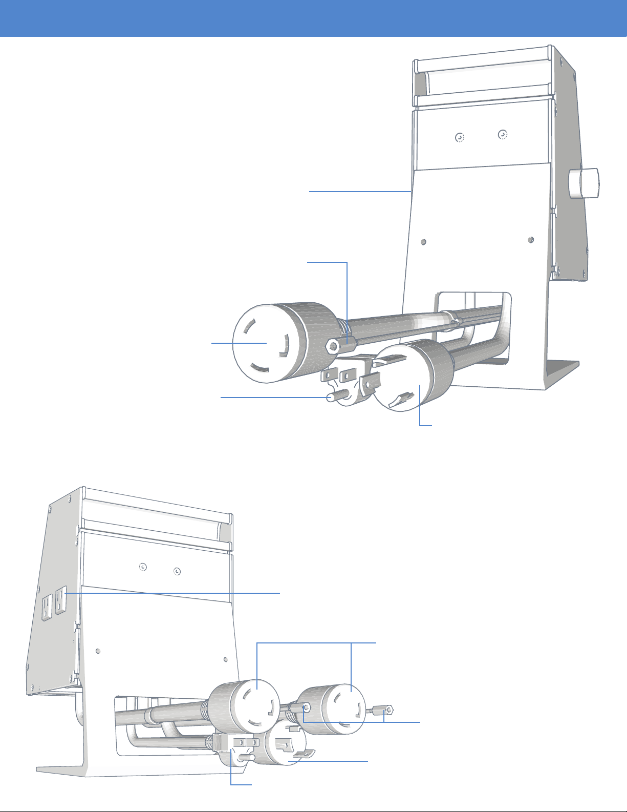
1V eCONTROLLER CONNECTIONS
(2) 110VAC NEMA 5-15P Side Mounted Controller
Receptacles (3 Amps max per outlet)
(1) 3.5MM Thermoprobe Connection Interface
(1) L6 - 30R Element Output
(1) 110VAC Accessory Power Input
2V eCONTROLLER CONNECTIONS
(1) L6 - 30P 208-240VAC
Main Power Input
(2) 110V NEMA 5-15P Side Mounted Controller
Receptacles (3 Amps max per outlet)
(2) L6 - 30R Element Output
(2) 3.5MM Thermoprobe
Connection Interface
(1) L6 - 30P 208-240VAC Main power input
(1) 110VAC Accessory Power Input
Page 4
Page 5
ASSEMBLY (CONTINUED)
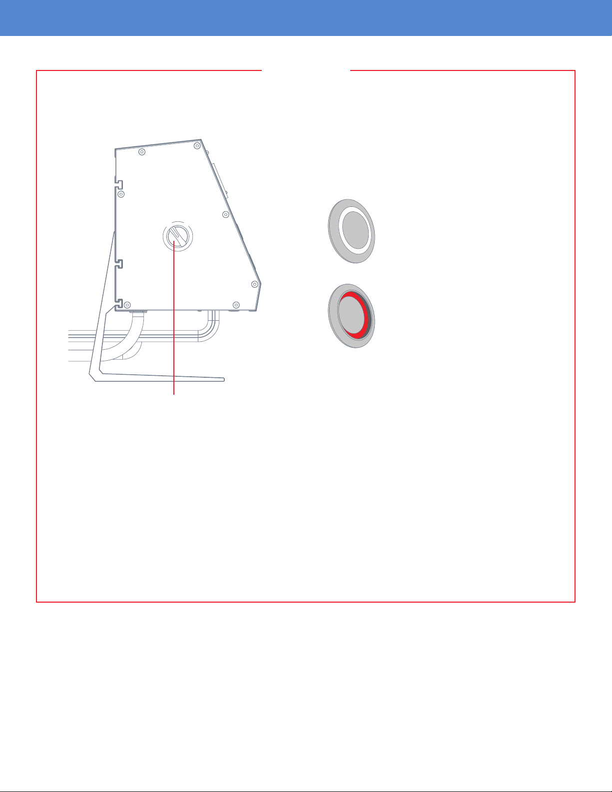
WARNING
Before plugging in the controller, ensure that both the heater activation button as well as the side
mounted on/off switch are not currently engaged. This will prevent accidental dry ring.
ACTIVATION BUTTON
O
O
F
N
F
N
F
F
O
O
Off Position
- Button is not recessed
- No indicator light
On Position
- Button is recessed
- Red indicator light
Side Mounted “ON/OFF” Switch in “OFF” Position
Always verify the element is fully submerged in water before activating the heater element. Dry
ring the element will cause irreversible damage to the element coil and void the element’s
warranty. Prolonged dry ring can cause damage to the vessel and other components, and can
result in personal injury or property damage.
Make sure that the unit is connected to a dedicated GFCI circuit.
Wear proper PPE (Personal Protective Equipment) when using the equipment. This would
include protective eyewear, gloves and apparel that would aid in prevention of scalding from
boiling water.
Page 5
Page 6

BREW DAY OPERATIONS (CONTINUED)
IMPORTANT
It is recommended to perform a “water brew” on the system before using real ingredients. This will
allow you to familiarize yourself with the controller’s operation, processes, temperature ramp rates, and
temperature losses during transfers. Record data and observations carefully so that you can calculate
or adjust water volumes and temperatures based on recipe prole, ambient grain temperatures and
any other outside variables.
eCONTROLLER ACTIVATION
O
O
F
N
F
N
F
F
O
O
Side Mounted “ON/OFF” Switch Heater and Accessory Activation Buttons
ACTIVATION BUTTONS
Off Position
- Button is not recessed
- No indicator light
After ensuring all the rear electrical connections have be made, the unit can be powered on via the side
mounted “ON/OFF” switch. Make sure that both the heater activation button as well as the accessory
buttons are in the “OFF” position as shown in the graphic above.
Heater On Position
- Button is recessed
- Red indicator light
Accessory On Position
- Button is recessed
- Blue indicator light
Page 6
Page 7

BREW DAY OPERATIONS (CONTINUED)
O
O
F
N
F
N
F
F
O
O
MAN (Manual) Mode
Once the side mounted “ON/OFF” switch is turned to the “ON” position, both controller adjustments and
heater activation can begin.
At the top of the controller near the PID read out, there is a rocker switch for going in between “MAN”
(Manual) or “AUTO” mode changes.
MANUAL MODE
The eKettle elements have been designed to support voltage modulation to ne tune the element wattage
output. The benet of this design is that it allows the user to dial in a perfect rolling boil by reducing
element output instead of a more traditional on/off modulation. When the eController is in “MAN” mode,
the set value on the temperature controller is indicative of the percentage of total wattage output for
the element. For example, if the set value is at 100, that is 100% of element output, and if the set value
is at 50, that means the power level is reduced to 50% of element output. Adjustment can be made
from 0-100%.
Once you have the percentage dialed in, you can now activate the heater by depressing the heater
activation button. The button will glow red to let you know the button has been depressed. Press down
on the button again to deactivate power.
“MAN” mode is recommended for boil kettle operation.
Always verify the element is fully submerged in water before activating the heater element.
Dry ring the element will cause irreversible damage to the element coil and void the
element’s warranty.
Page 7
Page 8

BREW DAY OPERATIONS (CONTINUED)
O
O
F
N
F
N
F
F
O
O
Auto Mode
AUTO MODE
When the eKettle is in “AUTO” mode, the temperature controller is set up to modulate element output
based on a set temperature. This is used to maintain a specic temperature such as during a kettle
souring process or for use as a HLT. For example, if 172 is entered into the set value, the controller will
maintain the temperature of the liquid inside the kettle at 172 degrees Fahrenheit.
Once you have the temperature dialed in, you can now activate the heater by depressing the heater
activation button. The button will glow red to let you know the button has been depressed. Press
down on the button again to deactivate power. The element can also be shut down by adjusting the
temperature below its setpoint in “AUTO” Mode.
Always verify the element is fully submerged in water before activating the heater element.
Dry ring the element will cause irreversible damage to the element coil and void the
element’s warranty.
Page 8
Page 9

BREW DAY OPERATIONS (CONTINUED)
CONTROLLER ADJUSTMENT
Temperature or percentage can easily be adjusted via the up and down arrows located on the controller.
You can also use the “<<PF” button to move over decimal places to make this process go a little quicker
vs holding the up or down arrows.
Current Value
Decimal Location
Set Value
Increase Temperature/Percentage
Decrease Temperature/Percentage
Page 9
Page 10

BREW DAY OPERATIONS (CONTINUED)
SIDE MOUNTED 110VAC ACCESSORY OUTLET ACTIVATION
Included are (2) 110VAC NEMA 5-15R side-mounted receptacles (3A max per outlet) that can be used
for a variety of accessories ranging from pumps to lighting.
ACCESSORY ONE
120V - 3A
ACCESSORY TWO
120V - 3A
(2) 110V NEMA 5-15R Side Mounted Controller
Receptacles (3 Amps max per outlet)
110VAC Accessory Power Input
The 110VAC plug coming from the rear of the eController must be connected to a power outlet in
order for the two side-mounted receptacles to function. Once this connection has been made, both the
“Accessory One” and “Accessory Two” buttons located on the front of the controller can activate the
corresponding “Accessory One” and “Accessory Two” outlets. Activation is simply made by depressing
the button. A blue glow will appear around the button to let you know that the accessory outlet is
currently activated. Press and release the button once more to deactivate power.
Page 10
Page 11

BREW DAY OPERATIONS (CONTINUED)
2V OPTIONS
The 2V eController includes two PID controllers as well as an element selection switch. The two PID
controllers are labeled as “HLT/MASH” and “BOIL KETTLE” on the face of the eController. The element
selector switch’s function is to switch the power output to either the “HLT/MASH” element or “BOIL
KETTLE” element.
Due to voltage and amperage requirements, only one element can be activated at a time on a 208VAC
to 240VAC circuit.
The procedure to adjust temperature and percentage on the eController 2V is identical to the eController
1V. The 2V does, however, include an element selector switch that allows you to select which element
you want to activate. When using the eController 2V, be sure to pay close attention to which element
you activate so that you do not accidentally dry re an element that may not be completely submerged.
Once the selector switch is in the desired position, the element can be turned on by depressing the
“HEATER ON” button. To deactivate power, simply press and release the button once more.
Only the boil kettle portion of the 2V controller has voltage modulation to ne tune the element wattage
output via the “MAN” or “AUTO” switch setup. This rocker switch is located above the controller read out
marked “BOIL KETTLE”. The “HLT/MASH” controller only supports an auto PID tuning setting based
on a set point since this is used to maintain to maintain a specic temperature for both a HLT and
mash tun.
Always verify the element is fully submerged in water before activating the heater element. Dry ring
the element will cause irreversible damage to the element coil and void the element’s warranty.
Element Selector Switch
Page 11
Page 12

eBREWING KIT ASSEMBLY
eBREWING 1V KIT
Ss eKettle
110VAC Accessory Power Cord
L6 - 30P 208-240VAC Main Power Input
Thermoprobe Cord
Thermoprobe Connection
Element Cord
L6 - 30R Element Output
Page 12
Page 13

WARRANTY
Ss Brewtech provides a one year limited warranty to the original purchaser that our product(s) will be
free from manufacturing defects in material and workmanship. The limited warranty covers only those
defects and/or product failures that arise as a result of normal use, and does not cover any problems
that originate from:
- Improper cleaning, care and maintenance
- Modications made to a product
- Operation outside the product’s published specications
- Damage caused by incorrect assembly
- Exceeding recommended operational limits
Ss Brewtech reserves the right to request the original purchaser to return the defective item, at the
purchaser’s expense, before processing the warranty claim and issuing a replacement. If a direct
replacement is no longer available, a product that serves the same purpose with equal or greater value
shall be awarded. Ss Brewtech, at its discretion may also opt to simply refund the full purchase price in
lieu of replacing the product.
The Ss Brewtech limited warranty is only applicable to customer-direct sales of home brewing equipment.
LIMITATIONS
Ss Brewtech makes no warranty of any nature beyond what is contained in this limited warranty.
Ss Brewtech is not responsible for representations made about a product by another retailer.
Page 13
Page 14

SsBrewtech.com
REV 12072018
 Loading...