

Page 1
Data Sheet
DCW 2004 B / Art. No.: 1025
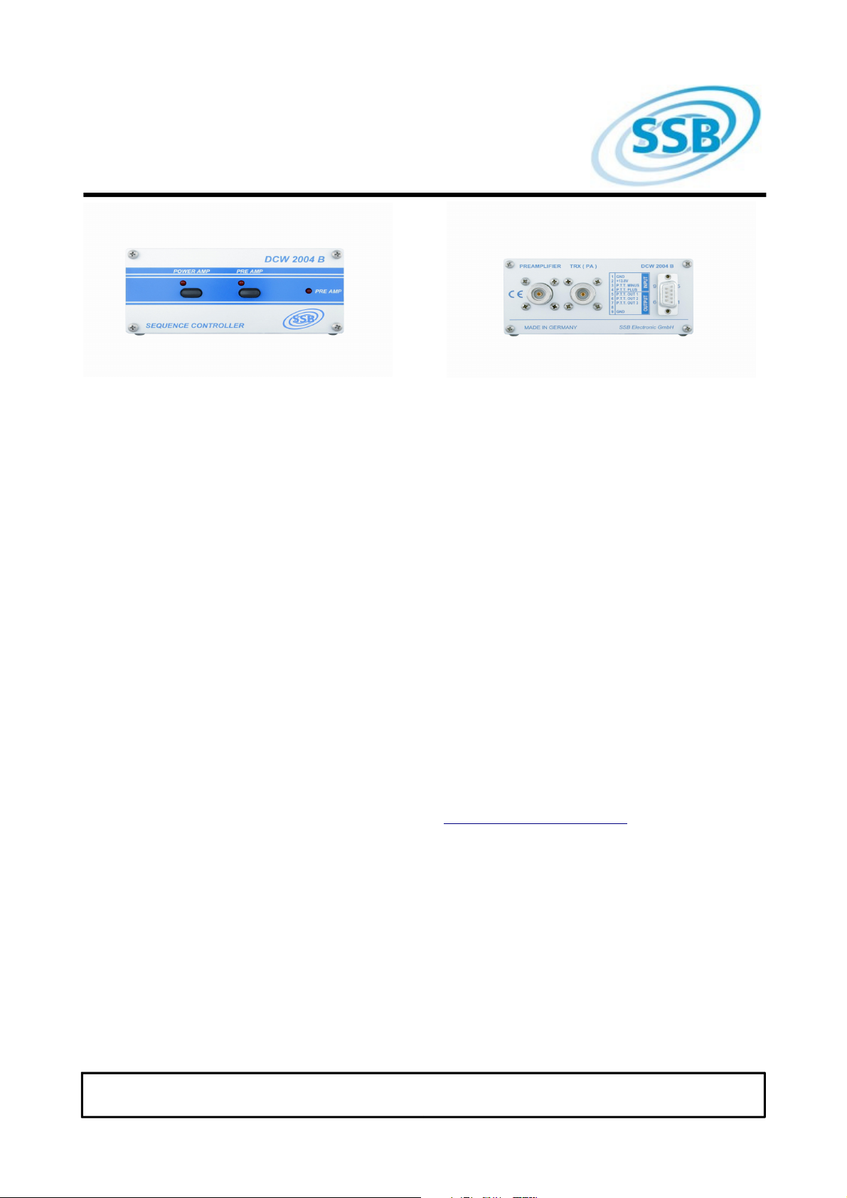
The remote powering coupler DCW 2004 B
allows a comfortable remote coupling of our
SUPER-AMP preamplifiers via the coaxial
cable as well as for delayed switching of HFlinear amplifiers.
The sequential operation of the DCW 2004 B
avoids reliably any damage to the preamplifier
that may be caused by HF-spikes during
switching. It offers 3 switching outputs in total,
which have ascending delay times. So not
only linear amplifiers but other devices, like
transverters, can be switched on with defined
times.
The DCW 2004 B is designed for the
amplifiers
SP 6 (6m-band),
SP 2000 (2m-band) and
SP 7000 (70cm band)
The PTT switching input of the DCW 2004 B
accepts a circuit against ground or against + 5
... 12 V. The preamplifier and a linear
amplifier (if used) can be switched on or off as
required.
The HF-section of the DCW 2004 B offers a
very low insertion loss and a high shielding
factor.
Technical Data
Operating voltage 12 – 14 V
Frequency range 6 m, 2 m, 70cm
Power load 6 m / 750W SSB
2 m / 750W SSB
70 cm / 500 W SSB
Insertion loss 0.1 dB
Preamplifier voltage 0,5A max. loadable
P.T.T switching output 30 V at 0,5A max.
Relay switching outputs 30 V at 0,5A max.
- P.T.T-input switches at < 2V
+ P.T.T- input switches at > 5V
Dimensions 140 x 120 x 53 mm
Do not open the unit. It does not contain any
parts needing maintenance. If you need help
regarding technical matters, please contact
our team:
SSB-Electronic GmbH * Ostenfeldmark 21 * Lippstadt/Germany
Copyright * All rights reserved
www.ssb-electronic.de 25.1.2012
Page 2

Data Sheet
DCW 2004 B / Art. No.: 1025
Installation
After insertion of the preamplifier as close as
possible to the antenna feeding point, the
outdoor wiring is finished already.
In the shack the end of the downleading cable
has to be connected to "PREAMPLIFIER".
Please note that no filters or similar devices
may be inserted, as that would influence the
direct voltage transfer to the preamlifier! At the
socket „TRX (PA)", the HF-output of a
transceiver or power amplifier can be
connected.
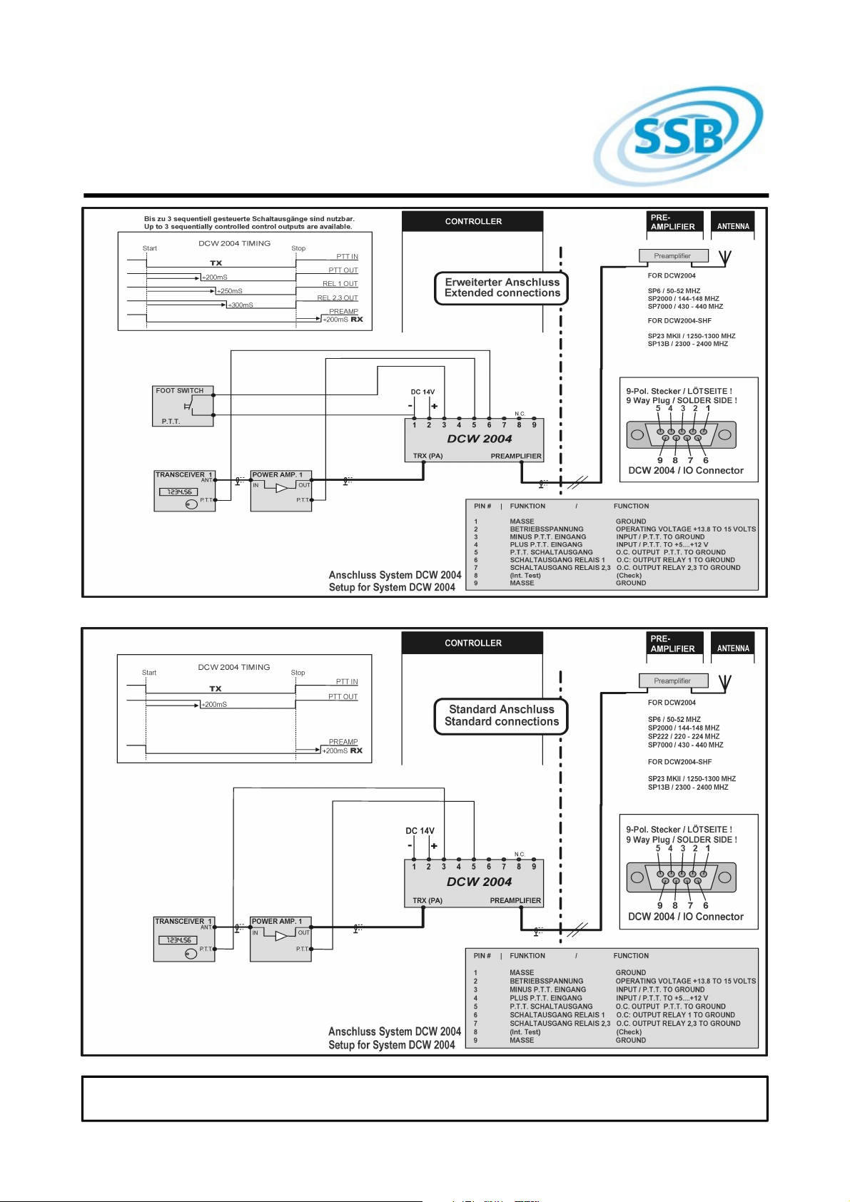
At the Sub-D socket the DC wiring has to be
proceeded as described in the wiring
diagarams on the subsequent page. Very long
coaxial cables may hinder a safe switching of
the preamplifier due to potential drop,
especially at low outside temperatures. Hence
we recommend not to undershoot an
operating voltage of 13.8 Volt at the coupler!
Operation of the remote feeding coupler
After switching on the operating voltage, a
short test of the electrical connection to the
remote antenna switch is carried out. When
wiring is recognized as ok, the unit is switched
on using factory default settings: Preamplifier
and final amplifier are activated. When
switched on again, the unit will start with the
settings choosen before. (Last state function)
In case of a short the right LED "PreAmp"
blinks quickly.
However, an interruption of the line cannot be
recognized!
Operation with a linear amplifier
For pperation with a linear amplifier the DCW
2004 B is equipped with a PTT-switching
output, which adds a defined delay to the final
stage. At the PTT switching output (point 5 of
the SUB-D socket) an Open-Collector
switching output is available, which can direct
a max. current of 500 mA to ground. Hence it
is secured that the preamplifier is switched off
before any transmitting power is activated.
Important: Please make sure to disable a
HF-VOX control that might be built-in to
your final amplifier!
The DCW 2004 B offers three outputs in total
which have ascending latency times. These
switching outputs can, for example, used for
activating further relays, what may be of help
for more complex systems.
SSB-Electronic GmbH * Ostenfeldmark 21 * Lippstadt/Germany
Copyright * All rights reserved
www.ssb-electronic.de 25.1.2012
Page 3
Data Sheet
DCW 2004 B / Art. No.: 1025
SSB-Electronic GmbH * Ostenfeldmark 21 * Lippstadt/Germany
Copyright * All rights reserved
www.ssb-electronic.de 25.1.2012
Page 4
Data Sheet
DCW 2004 B / Art. No.: 1025
Disposal of your old appliance
This product is covered by the
European Community directive
2002/96/EC. 2.
All electrical and electronic
products should be disposed of
separately from the municipal
waste stream via designated
collection facilities appointed by the
government or by the local authorities. The
correct disposal of your old appliance will help
prevent potential negative consequences for
the environment and the human health.
For more detailed information about the
disposal of your old appliance, please consult
your city office, waste disposal service or the
shop where you purchased the product.
Within Germany, the above regulations are
also valid for the disposal of batteries and
accumulators accordingly.
Declaration of Conformity
Herewith we declare that this
product complies with all relevant
regulations for the product within
the guidelines 73/23/EWG,
89/336/EWG and 99/5/EG of the
Council:
EN 301 489-15 Electromagnetic compatibility
and Radio Spectrum Matters (ERM)
Electromagnetic Compatibility (EMC) standard
for radio equipment and services.
Part 15: specific conditiones for commercially
available amateur radio equipment.
EN 301 783-1 Electromagnetic compability
and Radio Spectrum Matters (ERM); Land
Mobile Service; commercially available
amateur radio equipment.
Part 1: technical characteristics and methods
of measurement.
EN 301 783-2 Electromagnetic compability
and amateur radio equipment.
Part 2: harmonized EN covering essential
requirements under articel 3.2 of the R&TTE
Directive.
EN 60950-1:2001 Information technology
equipment – safety.
Part 1: General requirements.
Manufacturer:
SSB-Electronic GmbH
Ostenfeldmark 21
59557 Lippstadt
Contact:
E-Mail: [email protected]
Telephone: +49(0)2941 – 93385 - 0
SSB-Electronic GmbH * Ostenfeldmark 21 * Lippstadt/Germany
Copyright * All rights reserved
www.ssb-electronic.de 25.1.2012
 Loading...