

Delay On Make (Operate)Delay On Make (Operate)
Delay On Make (Operate)
Delay On Make (Operate)Delay On Make (Operate)
TS1 Versa-Timer
Timing Module
DescriptionDescription
Description
DescriptionDescription
Versa-Timer offers proven reliability and performance with years of use in OEM equipment and commercial
applications. This encapsulated general use timing module is capable of controlling load currents ranging from
5 mA to 1 A. May be connected in series with contactors, relays, valves, solenoids, small motors, and lamps.
Two Terminal Series
Connection with Load
5 mA ... 1 A Load Currents
Totally Solid State –
Encapsulated
+/-2% Repeat Accuracy
Fixed or Adjustable
Delays From 50 ms ... 10 m
in 8 Ranges
Approvals:
AccessoriesAccessories
Accessories
AccessoriesAccessories
B B
B
B B
External adjust
potentiometer
A A
A
A A
P/N:
P1004-XXP1004-XX
P1004-XX (fig A)
P1004-XXP1004-XX
P1004-XX-X P1004-XX-X
P1004-XX-X (fig B)
P1004-XX-X P1004-XX-X
Mounting bracket
P1023-6 P1023-6
P/N:
P1023-6
P1023-6 P1023-6
Female quick connect
P/N:
P1015-64P1015-64
P1015-64
P1015-64P1015-64
Quick connect to
screw adaptor
P1015-18 P1015-18
P/N:
P1015-18
P1015-18 P1015-18
(AWG 14/16)
OperationOperation
Operation
OperationOperation
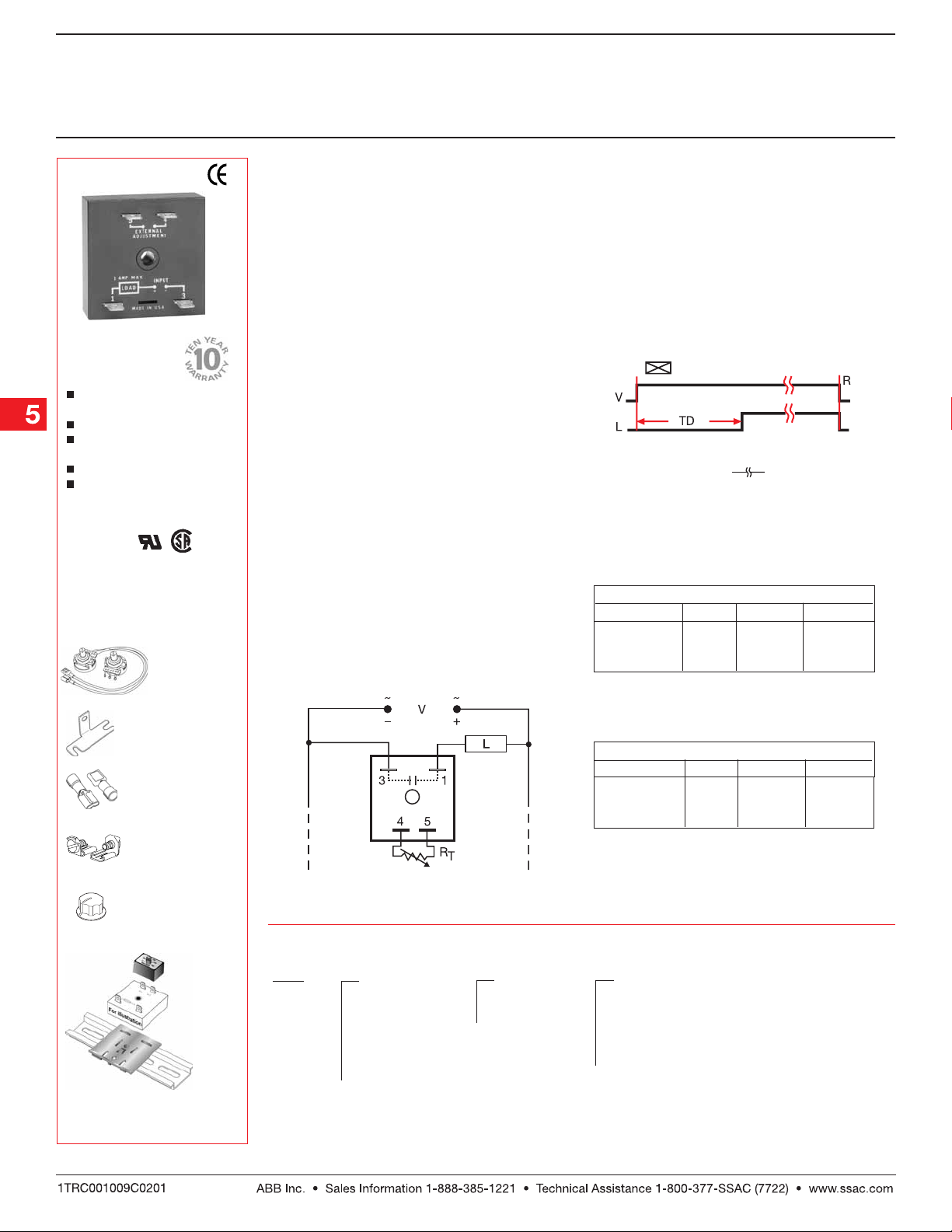
Upon application of input voltage, the time delay
begins. The output is de-energized before and during
the time delay. At the end of the time delay, the output
energizes and remains energized until input voltage is
removed.
Reset:Reset:
Reset: Removing input voltage resets the time delay
Reset:Reset:
and output.
ConnectionConnection
Connection
ConnectionConnection
FunctionFunction
Function
FunctionFunction
Delay On Make
V = Voltage L = Load R = Reset
TD = Time Delay
12 VDC
Time Delay
11
1 – 0.05 ... 1 s
11
22
2 – 0.5 ... 20 s
22
33
3 – 2 ... 60 s
33
44
4 – 5 ... 120 s
44
Time Delay VTP P/N
11
1 – 0.05 ... 3 s
11
22
2 – 0.5 ... 60 s
22
33
3 – 2 ... 180 s
33
44
4 – 5 ... 600 s
44
VTP P/N
VTP2A
VTP2E
VTP2F
VTP2H
All Other Voltages
VTP4B
VTP4F
VTP4J
VTP5N
= Undefined time
Fig. A P/N
P1004-16
P1004-16
P1004-16
P1004-16
Fig. A P/N Fig. B P/N
P1004-12
P1004-12
P1004-12
P1004-13
Fig. B P/N
P1004-16-X
P1004-16-X
P1004-16-X
P1004-16-X
P1004-12-X
P1004-12-X
P1004-12-X
P1004-13-X
Versa-knob
P0700-7 P0700-7
P/N:
P0700-7
P0700-7 P0700-7
Plug-on adjustment
module
P/N:
VTP(X)(X)VTP(X)(X)
VTP(X)(X)
VTP(X)(X)VTP(X)(X)
DIN rail P/Ns:
017322005 017322005
017322005 (St eel )
017322005 017322005
C103PM C103PM
C103PM (Al )
C103PM C103PM
←
→
DIN rail adaptor
P1023-20 P1023-20
P/N:
P1023-20
P1023-20 P1023-20
See accessory pages for
specifications.
Load may be connected to terminal 3 or 1.
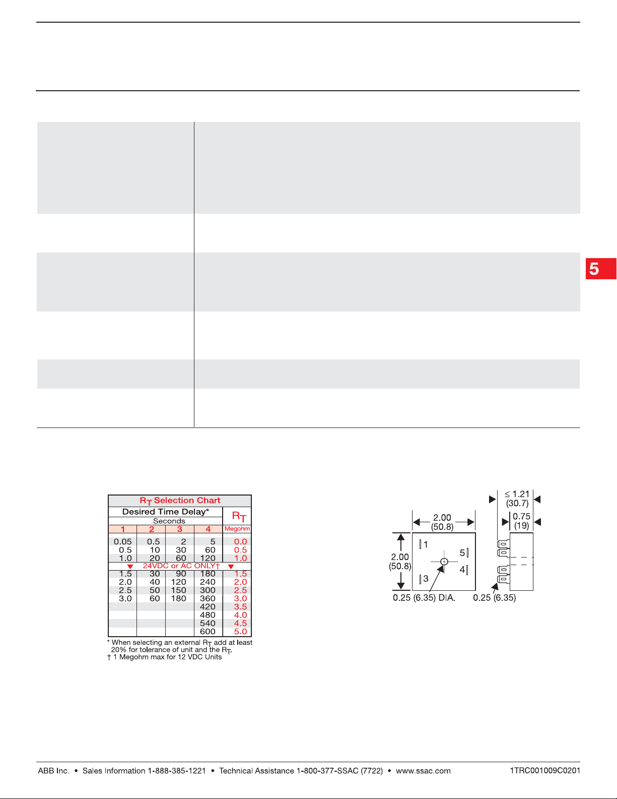
RT is used when external adjustment is ordered.
OrOr
dering Tdering T
Or
dering T
OrOr
dering Tdering T
TS1 TS1
TS1
TS1 TS1
SeriesSeries
Series
SeriesSeries
Example P/N:Example P/N:
Example P/N:
Example P/N:Example P/N:
ableable
able
ableable
X X
X
X X
InputInput
Input
InputInput
––
11
- -
–
1
- 12 V DC
––
11
- -
––
2 2
- -
–
2
- 24 V AC
––
2 2
- -
––
33
- -
–
3
- 24 V DC
––
33
- -
––
44
- -
–
4
- 120 V AC
––
44
- -
––
55
- -
–
5
- 120 V DC
––
55
- -
––
66
- -
–
6
- 230 V AC
––
66
- -
TS1122 TS1122
TS1122 Fixed –
TS1122 TS1122
X X
X
X X
AdjustmentAdjustment
Adjustment
AdjustmentAdjustment
– –
11
- -
–
1
-
– –
11
- -
Fixed
– –
22
- -
–
2
-
– –
22
- -
External
Adjust
TS1411.5TS1411.5
TS1411.5
TS1411.5TS1411.5
X X
X
X X
Time Delay*Time Delay*
Time Delay*
Time Delay*Time Delay*
12 V DC12 V DC
12 V DC
12 V DC12 V DC
––
11
- -
–
1
- 0.05 … 1 s 0.05 ... 3 s
––
11
- -
––
2 2
- -
–
2
- 0.5 … 20 s
––
2 2
- -
––
33
- -
–
3
- 2 … 60 s 2 ... 180 s
––
33
- -
––
4 4
- -
–
4
- 5 … 120 s 5 ... 600 s
––
4 4
- -
All OtherAll Other
All Other
All OtherAll Other
VoltagesVoltages
Voltages
VoltagesVoltages
0.5 ... 60 s
*If Fixed Delay is selected, insert delay
0.050.05
[
0.05 ...
0.050.05
120120
120] (12V DC) or [
120120
0.050.05
0.05 ...
0.050.05
(other voltages) in secs.
Low Voltage Products & Systems5.28
600600
600]
600600
TS102B01 06.09.04
Delay On Make (Operate)Delay On Make (Operate)
Delay On Make (Operate)
Delay On Make (Operate)Delay On Make (Operate)
TS1 Versa-Timer
Timing Module
Technical Data Technical Data
Technical Data
Technical Data Technical Data
Time DelayTime Delay
Time Delay
Time DelayTime Delay
Type Analog circuitry
Range 12 V DC 0.05 ... 120 s in 4 adjustable ranges or fixed (1 MΩ max. R
Other Voltages 0.05 ... 600 s in 4 adjustable ranges or fixed
Repeat Accuracy +/-2% or 20 ms, whichever is greater
Tolerance (Factory Calibration) ≤ +/-10%
Recycle Time After timing – ≤ 16 ms
Time Delay vs. Temperature & Voltage ≤ +/-10%
InputInput
Input
InputInput
Voltage 12, 24 or 120 V DC; 24, 120, or 230 V AC
Tolerance +/-20%
Line Frequency 50 ... 60 Hz
OutputOutput
Output
OutputOutput
Type Solid state
Form Normally Open, open during timing
Maximum Load Current 1 A steady state, 10 A inrush at 60°C
Minimum Holding Current 5 mA
Voltage Drop ≅ 2.5 V at 1 A
ProtectionProtection
Protection
ProtectionProtection
Circuitry Encapsulated
Dielectric Breakdown ≥ 2000 V RMS terminals to mounting surface
Insulation Resistance ≥ 100 MΩ
Polarity DC units are reverse polarity protected
MechanicalMechanical
Mechanical
MechanicalMechanical
Mounting Surface mount with one #10 (M5 x 0.8) screw
Termination 0.25 in. (6.35 mm) male quick connect terminals
EnvironmentalEnvironmental
Environmental
EnvironmentalEnvironmental
Operating/Storage Temperature -40°C ... +80°C / -40°C ... +85°C
Humidity 95% relative, non-condensing
Weight ≅ 2.4 oz (68 g)
During timing – 0.1% of time delay or 75 ms, whichever is greater
)
T
Mechanical View Mechanical View
Mechanical View
Mechanical View Mechanical View
Inches(Millimeters)
TS102B01 06.09.04
Low Voltage Products & Systems 5.29
 Loading...