

Page 1
Knob Adjustable Time Delays
Fixed or Adjustable Delays
From 0.05 ... 600 s in Ranges
Analog Circuitry +/-2%
Repeat Accuracy
AC and DC Operating
Voltages are Available
10 A, Isolated SPDT and
DPDT Contacts
Approvals:
Single Shot, Interval (Pulse Former)Single Shot, Interval (Pulse Former)
Single Shot, Interval (Pulse Former)
Single Shot, Interval (Pulse Former)Single Shot, Interval (Pulse Former)
TRS Series
Time Delay Relay
DescriptionDescription
Description
DescriptionDescription
The TRS Series combines a 10 A isolated electromechanical relay output with analog timing circuitry. False
trigger of the TRS by a transient is unlikely because of the complete isolation of the circuit from the line prior to
initiation. The initiate contact is common to one side of the line and may be utilized to operate other loads.
Installation is easy due to the TRS's industry standard 8 or 11 pin plug-in base wiring.
OperationOperation
Operation
OperationOperation
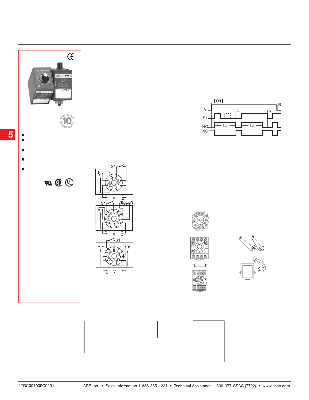
Input voltage must be applied to the input before and
during timing. Upon momentary or maintained closure
of the initiate switch (leading edge triggered), the output
energizes for a measured interval of time. At the end of
the delay , the output de-energizes. Opening or reclosing
the initiate switch during timing has no affect on the time
delay. Applying input voltage with the initiate switch
closed will energize the load and begin the time delay.
Reset: Reset:
Reset: Reset occurs when the time delay is complete
Reset: Reset:
and the initiate switch is opened. Loss of input voltage
resets the time delay and output.
ConnectionConnection
Connection
ConnectionConnection
**
8 Pin Octal SPDT
FunctionFunction
Function
FunctionFunction
Single Shot
V = Voltage S1 = Initiate Switch
TD = Time Delay R = Reset
NO = Normally Open NC = Normally Closed
** 8 pin models used in
combination with P1011-6
socket only.
OrOr
dering Tdering T
Or
dering T
OrOr
dering Tdering T
TRS TRS
TRS
TRS TRS
SeriesSeries
Series
SeriesSeries
ableable
able
ableable
XX
X
XX
InputInput
Input
InputInput
24A 24A
–
24A - 24 V AC
24A 24A
24D 24D
–
24D - 24 V DC/
24D 24D
28 V DC
110D110D
–
110D - 110 V DC
110D110D
120A 120A
–
120A - 120 V AC
120A 120A
230A 230A
–
230A - 230 V AC
230A 230A
Example P/N:Example P/N:
Example P/N:
Example P/N:Example P/N:
TRS120A2Y30TRS120A2Y30
TRS120A2Y30 Fixed:
TRS120A2Y30TRS120A2Y30
11 Pin SPDT
11 Pin DPDT
S1 = Initiate Switch
Relay contacts are isolated. Dashed lines are
internal connections.
RT is used when external adjustment is ordered.
XX
X
XX
Adjustment and Output FormAdjustment and Output Form
Adjustment and Output Form
Adjustment and Output FormAdjustment and Output Form
1 1
–
1 - Fixed, Octal, SPDT
1 1
10 10
–
10 - Fixed, 11 Pin, DPDT
10 10
2 2
–
2 - Knob Adjust, Octal, SPDT
2 2
3 3
–
3 - Lock Shaft Adjust, Octal, SPDT
3 3
4 4
–
4 - Knob Adjust, 11 Pin, DPDT
4 4
7 7
–
7 - Ext. Adjust, 11 Pin, SPDT without
7 7
XX
X
XX
Time TTime T
Time T
Time TTime T
X X
–
X - +/-20%
X X
Y Y
–
Y - +/-10%
Y Y
ZZ
–
Z- +/- 5%
ZZ
Potentiometer
TRS24D10Z1 TRS24D10Z1
TRS24D10Z1
TRS24D10Z1 TRS24D10Z1
oleranceolerance
olerance
oleranceolerance
AccessoriesAccessories
Accessories
AccessoriesAccessories
Octal socket
for UL Listing
P1011-6 P1011-6
P/N:
P1011-6
P1011-6 P1011-6
11 pin socket
NDS-11 NDS-11
P/N:
NDS-11
NDS-11 NDS-11
Octal
8 pin socket
NDS-8 NDS-8
P/N:
NDS-8
NDS-8 NDS-8
See accessory pages for specifications.
XX
X
XX
Time Delay *Time Delay *
Time Delay *
Time Delay *Time Delay *
(Seconds)(Seconds)
(Seconds)
(Seconds)(Seconds)
– 0.05 ...
– 0.05 ...
– 0.05 ...
– 0.1 ...
– 0.1 ...
– 1 ...
– 1 ...
– 2 ...
1 1
1
1 1
2 2
2
2 2
3 3
3
3 3
5 5
5
5 5
10 10
10
10 10
30 30
30
30 30
60 60
60
60 60
120120
120
120120
–2 ...
–7 ...
–7 ...
–7 ...
–7 ...
–7 ...
–7 ...
180180
180
180180
240240
240
240240
300300
300
300300
360360
360
360360
420420
420
420420
*If Fixed Delay is
480480
480
480480
selected, insert delay
600600
600
600600
0.050.05
[
0.05 ...
0.050.05
Hold down clips
P/Ns:
PSC8 PSC8
PSC8 (NDS-8)
PSC8 PSC8
PSC11 PSC11
PSC11 (NDS-11)
PSC11 PSC11
Panel mount kit
BZ1 BZ1
P/N:
BZ1
BZ1 BZ1
600600
600] in seconds
600600
TRS02B01 07.07.04
Low Voltage Products & Systems5.98
Page 2
Single Shot, Interval (Pulse Former)Single Shot, Interval (Pulse Former)
Single Shot, Interval (Pulse Former)
Single Shot, Interval (Pulse Former)Single Shot, Interval (Pulse Former)
TRS Series
Time Delay Relay
Technical Data Technical Data
Technical Data
Technical Data Technical Data
Time DelayTime Delay
Time Delay
Time DelayTime Delay
Type Analog circuitry
Range 50 ms ... 10 m in 15 adjustable ranges or fixed
Repeat Accuracy +/-2% or 20 ms, whichever is greater
Fixed Time Tolerance & Setting Accuracy +/-5, 10, or 20%
Initiate Time ≤ 70 ms
Reset Time ≤ 75 ms
Recycle Time ≤ 250 ms
Time Delay vs. Temperature & Voltage ≤+/-10%
InputInput
Input
InputInput
Voltage 24 or 110 V DC; 24, 120, or 230 V AC
Tolerance 24 V DC/AC -15% ... +20%
110 ... 230 V AC/DC -20% ... +10%
Frequency 50 ... 60 Hz
Power Consumption ≤ 3.25 W
OutputOutput
Output
OutputOutput
Type Electromechanical relay
Form Isolated SPDT or DPDT
Rating 10 A resistive at 120/240 V AC & 28 V DC; 1/3 hp at 120/240 V AC
Life Mechanical: 1 x 10⁷; Electrical: 1 x 10
ProtectionProtection
Protection
ProtectionProtection
Insulation Resistance ≥ 100 MΩ
Isolation Voltage ≥ 1500 V RMS between input & output terminals
Polarity DC units are reverse polarity protected
MechanicalMechanical
Mechanical
MechanicalMechanical
Mounting Plug-in socket
Termination 8 Pin octal or 11 Pin plug-in
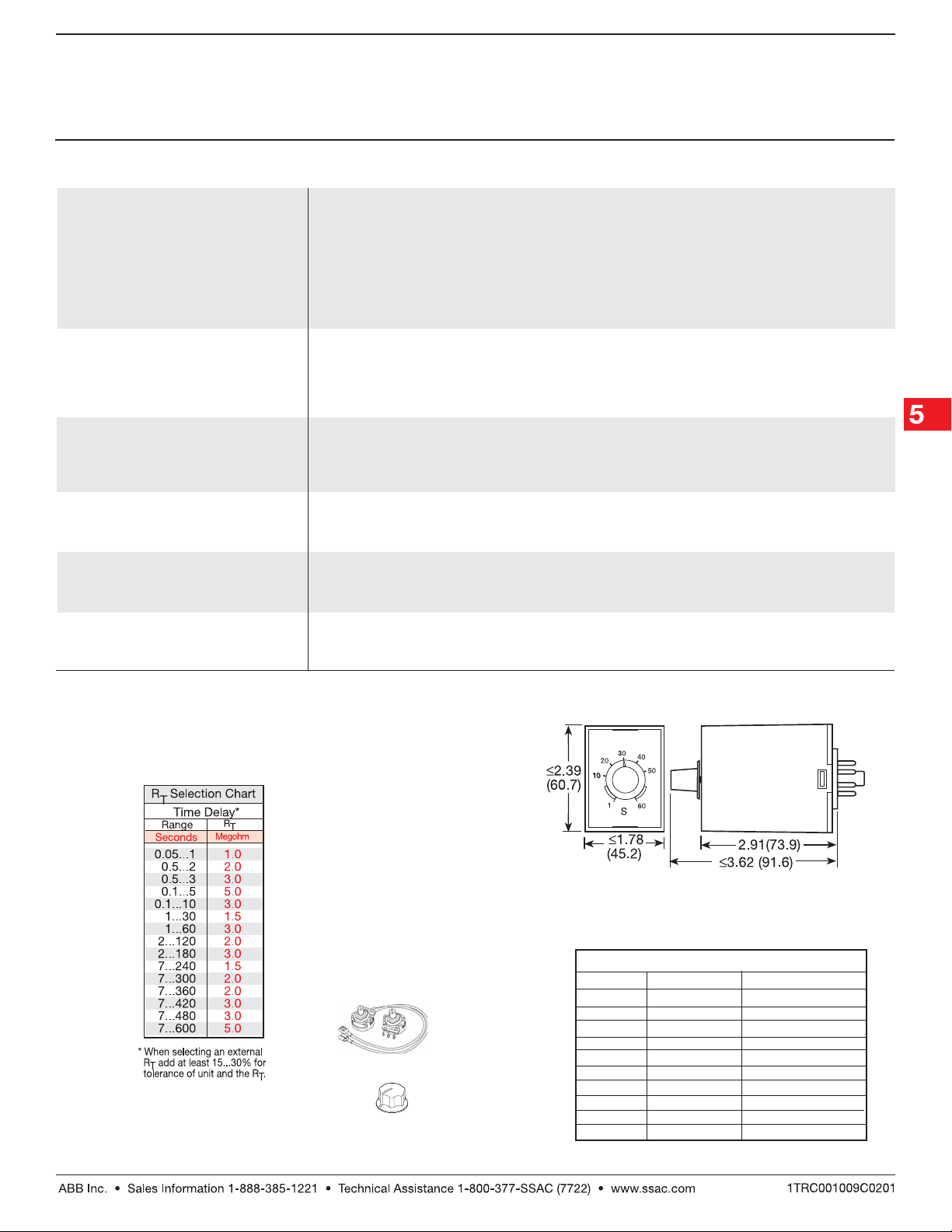
Package 3.62 x 2.39 x 1.78 in. (91.6 x 60.7 x 45.2 mm)
EnvironmentalEnvironmental
Environmental
EnvironmentalEnvironmental
Operating Temperature -20°C ... +65°C
Storage Temperature -30°C ... +85°C
Weight ≅ 6 oz (170 g)
6
Mechanical ViewMechanical View
Mechanical View
Mechanical ViewMechanical View
Inches (Millimeters)
ExterExter
nal Rnal R
Exter
AccessoriesAccessories
Accessories
AccessoriesAccessories
ExterExter
Figure
BB
B
BB
TRS02B01 07.07.04
External adjust
AA
A
AA
potentiometer
P/Ns:
P1004-XX P1004-XX
P1004-XX (fig. A)
P1004-XX P1004-XX
P1004-XX-X P1004-XX-X
P1004-XX-X (fig . B )
P1004-XX-X P1004-XX-X
A
A
A
A
A
B
Versa-knob
P0700-7 P0700-7
P/N:
P0700-7
P0700-7 P0700-7
B
B
B
B
P/N Selection TP/N Selection T
nal R
P/N Selection T
nal Rnal R
P/N Selection TP/N Selection T
TT
T
TT
Value Part Number
1 M ohm
1.5 M ohm
2 M ohm
3 M ohm
5 M ohm
1 M ohm
1.5 M ohm
2 M ohm
3 M ohm
5 M ohm
ableable
able
ableable
P1004-16
P1004-15
P1004-14
P1004-12
P1004-13
P1004-16-X
P1004-15-X
P1004-14-X
P1004-12-X
P1004-13-X
Low Voltage Products & Systems 5.99
 Loading...