

Page 1
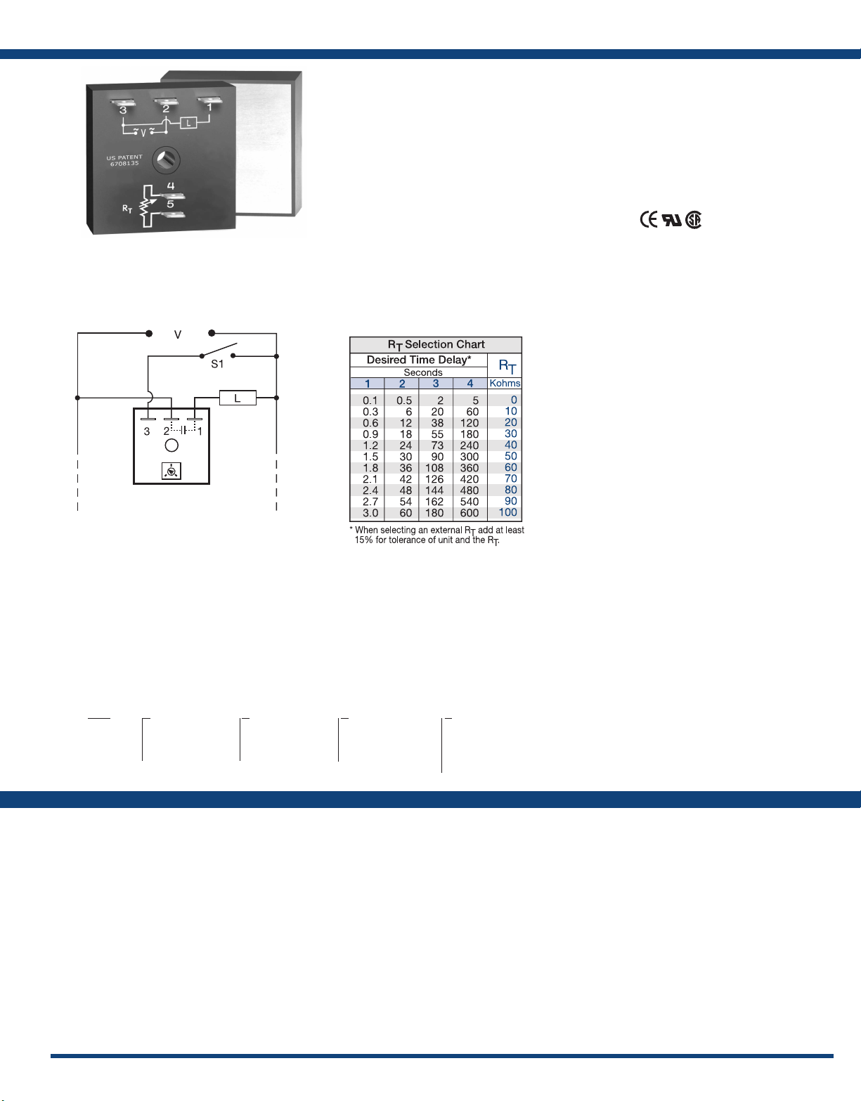
TH1 SeriesTimer - Delay-on-Make
Connection:
L1 N/L2
The TH1 Series is a solid-state relay and timer
combined into one compact, easy-to-use control.
This highly reliable device eliminates the need
for a separate solid-state relay. When mounted to
a metal surface, it can switch load currents up to
20A steady state, and 200A inrush.
Operation (Delay-on-Make):
Upon application of input voltage, the time delay begins.
The output is de-energized before and during the time
delay. At the end of the time delay, the output energizes
and remains energized until input voltage is removed.
Reset: Removing input voltage resets the time delay
and output.
For more information see:
Appendix A, pages 156-164 for function descriptions
and diagrams.
Appendix B, page 165, Figure 4 for dimensional drawing.
Features:
• High current load capacity up to 20A with
200A inrush
• Solid-state switching - no contact wear
or arcing
• Encapsulated
• Fixed or adjustable time delays from 0.1 - 600s
• ± 2% repeat accuracy
• ± 5% factory calibration
• Metallized mounting surface for heat transfer
Approvals:
Auxiliary Products:
• External adjust potentiometer:
P / N: P 10 0 4- 9 5
P/N: P1004-95-X
• Female quick connect:
P / N : P1 0 1 5 - 1 3 ( A W G 1 0 / 12 )
P/ N: P 1015 -64 (AWG 14/1 6)
• Quick connect to screw adaptor:
P/N: P1015-18
• Versa-knob: P/N: P0700-7
Available Models:
TH1A421
TH1B633
TH1C415
TH1C621
If desired part number is not listed, please call us to
see if it is technically possible to build.
S1 = Optional Low Current Initiate Switch
R
is used when external adjustment is ordered.
T
Order Table:
TH1
X
Output Rating
─A - 6A
─B - 10A
─C - 20A
X
Input Voltage
─2 - 24VAC
─4 - 120VAC
─6 - 230VAC
X
Adjustment
─1 - Fixed
─2 - External adjust
─3 - Onboard adjust
Specications
Time Delay
...............................0.1 - 600s in 4 adjustable ranges or xed
Range
Repeat Accuracy
Tolerance (Factory Calibration)
Time Delay vs Temp. & Voltage .........≤ ±10%
Recycle Time
Input
Voltage
Tolerance
AC Line Frequency
Power Consumption
Output
................................Solid state
Type
................................NO, open during timing
Form
Maximum Load Currents Output Steady State Inrush**
A 6A 60A
B 10A 100A
C 20A 200A
.....................±2% or 20ms, whichever is greater
.........................≤ 150ms
..............................24, 120, or 230VAC
............................±15%
...................50/60 Hz
.........≤ ± 5%
..................≤ 2VA
X
Time Delay*
─1 - 0.1 - 3s
─2 - 0.5 - 60s
─3 - 2 - 180s
─4 - 5 - 600s
Minimum Load Current
Voltage Drop
OFF State Leakage Current ............≅ 5mA @ 230VAC
Protection
Circuitry
Dielectric Breakdown
Insulation Resistance
Mechanical
Mounting **
Dimensions ..........................2 x 2 x 1.51 in. (50.8 x 50.8 x 38.4 mm)
Termination
Environmental
Operating / Storage Temperature
Humidity
Weight
**Must be bolted to a metal surface using the included heat sink compound. The maximum
mounting surface temperature is 90°C. Inrush: Non-repetitive for 16ms.
*If xed delay is selected, insert
delay (
0.1 - 600) in secs.
.........................≅ 2.5V at rated current
............................Encapsulated
.........................Surface mount with one #10 (M5 x 0.8) screw
..........................0.25 in. (6.35 mm) male quick connect terminals
............................95% relative, non-condensing
..............................≅ 3.9 oz (111 g)
...............100mA
.................≥ 2000V RMS terminals to mounting surface
..................≥ 100 MΩ
.......-20° to 60°C / -40° to 85°C
35
 Loading...