

Page 1
T2D SeriesTimer - Lockout
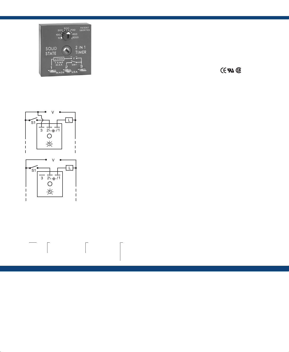
Connection:
L1 N/L2
L1 N/L2
1
Random Start
Plus Lockout
The T2D Series provides protection against short
cycling of compressors and other motors. At the
end of each operation, a lockout delay prevents
restarting the compressor or motor until the delay
is completed. 24VAC models can be used with
thermostats that include a cooling anticipator
resistor. It can be connected in series with the load
for delay-on-make operation.
Operation (Lockout with Random Start):
Connection #1: Upon application of input voltage, a
random start time delay begins. At the end of this time
delay, the output is energized. Lockout Delay: Input
voltage must be applied prior to and during timing.
When the thermostat or initiate switch opens, the output
de-energizes and the lockout time delay begins. At the
end of the lockout delay, the output is energized allowing
the load to immediately energize when the initiate switch
or thermostat closes.
Connection #2: Upon application of input voltage and
closure of initiate switch, the time delay begins. At the
end of the time delay, the output is energized and remains
energized until power is removed.
Reset: Removing power resets the output and the time
delay.
For more information see:
Appendix A, pages 156-164 for function descriptions
and diagrams.
Appendix B, page 165, Figure 1 for dimensional drawing.
Features:
• Lockout delay prevents rapid recycling
of compressor
• Random start delay helps prevent low
voltage starting
• Delay-on-make timer optional two
terminal series connection
• Totally solid-state 1A output
• 24VAC to 230VAC in 2 ranges
Approvals:
Auxiliary Products:
• Female quick connect:
P / N : P 1 0 1 5 - 6 4 (AW G 1 4/ 1 6 )
• Mounting bracket: P/N: P1023-6
• Quick connect to screw adaptor:
P/N: P1015-18
• DIN rail: P/N: C103PM (Al)
• DIN rail adaptor: P/N: P1023-20
Available Models:
T2D120A1150S
T2D120A15M
If desired part number is not listed, please call
us to see if it is technically possible to build.
2
Delay-on-Make
V = Voltage
L = Load
S1 = Initiate Switch or Thermostat
Order Table:
T2D
X
Input Voltage
─24A - 24VAC
─120A - 120/230VAC
X
Adjustment
─1 - Fixed
─2 - External adjust
X
Time Delay*
─1 - 1 - 100s
─2 - 10 - 1000s
─3 - 0.1 - 10m
─4 - 1 - 100m
Specications
Input
Voltage .................................24VAC, or 120/230VAC in 2 ranges
Tolerance ...............................±20%
AC Line Frequency ......................50/60 Hz
Output
Minimum Load Current ..................24VAC - 100mA; 120/230VAC - 40mA
Rating .................................1A steady state, 10A inrush at 60°C
Voltage Drop ............................≅ 2.5V @ 1A
Time Delay
Initiate Time ............................After timing - 16ms
Type ...................................Analog circuitry
Lockout & Random Start Delays ...........1s - 100m in 4 adjustable ranges or xed
Note: The lockout & random start delays
are the same length.
Tolerance ...............................Adjustable: ±30%; factory xed: ±30%
Repeat Accuracy ........................±1% or 20ms, whichever is greater
*If xed delay is selected, insert
delay (1 - 1000) followed by (S) sec.
or (0.1 - 100) (M) min.
Reset Time ..............................After timing - ≤ 16ms;
During timing - ≤ 200ms
Protection
Dielectric Breakdown ....................≥ 2000V RMS terminals to mounting surface
Insulation Resistance .....................≥ 100 MΩ
Mechanical
Mounting ..............................Surface mount with one #10 (M5 x 0.8) screw
Dimensions .............................2 x 2 x 1.21 in. (50.8 x 50.8 x 30.7 mm)
Termination .............................0.25 in. (6.35 mm) male quick connect terminals
Environmental
Operating / Storage Temperature ..........-20° to 60°C / -40° to 85°C
Humidity ...............................95% relative, non-condensing
Weight .................................≅ 2.4 oz (68 g)
Cooling Anticipator (24VAC Units Only)
Minimum Cooling Anticipator ............≥ 3,000 Ω
 Loading...