

Page 1
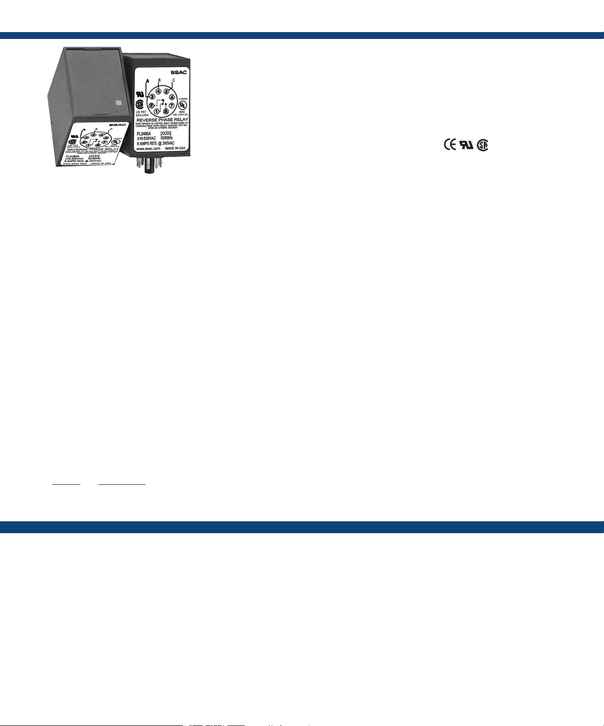
PLS SeriesVoltage Monitors
The PLS Series is a low cost phase sensitive control
that provides an isolated contact closure when the
proper A-B-C phase sequence is applied. Protects
sensitive 3-phase equipment and equipment
operators from reverse rotation. Designed to
be compatible with motor overloads or other
3-phase equipment protection devices. Protection
for equipment control centers where frequent
reconnection or electrical code makes reverse
rotation protection essential. Examples include:
mobile refrigerated containers, construction
equipment, hoists, pumps, conveyors, elevators
and escalators.
For more information see:
Appendix B, page 166, Figure 19 for dimensional drawing.
Appendix C, page 168, Figure 13 for connection diagram.
Operation
The internal relay and LED are energized when the phase sequence is correct. The output relay will not energize
if the phases are reversed. Reset is automatic upon correction of the fault.
Features:
• Protects against phase reversal
• Low cost protection, one unit for all sized
motors
• 3-wire connection for dela or wye systems
• Octal base connect - industry standard
wiring
• Isolated, SPDT output contacts
• Factory calibrated - no adjustments required
Approvals:
Auxilary Products:
• Panel mount kit: P/N: BZ1
• Octal 8-pin socket: P/N: OT08PC
• 3-phase fuse block/disconnect:
P/N: FH3P
• 2 Amp fuse: P/N: P0600-11
• Din rail: P/N: C103PM (Al)
Available Models:
PLS120A
PLS240A
PLS480A
Order Table:
Voltage
120VAC
208/240VAC
380/415VAC
440/480VAC
Part Number
PLS120A
PLS240A
PLS380A
PLS480A
Specications
Line Voltage
Type ...................................3-phase delta or wye with no connection to neutral
Nominal Voltage Minimum Voltage Maximum Voltage
120VAC 95VAC 135VAC
208/240VAC 175VAC 255VAC
380/415VAC 310VAC 430VAC
440/480VAC 380VAC 500VAC
AC Line Frequency ......................50/60 Hz
Phase Sequence .........................ABC
Response Times
Pull-in .................................≤ 300ms
Drop-out ...............................≤ 50ms
Output
Type ...................................Electromechanical relay, energized when the
phase sequence is correct
Form ...................................Isolated SPDT
Rating 120 & 240VAC . . . . . . 10A resistive @ 240VAC
380 & 480VAC .....8A resistive @ 240VAC
Maximum Voltage .......................250VAC
Protection
Isolation Voltage 120 & 240VAC ...≥ 1500V R MS inp ut to o utput
380 & 480VAC ...≥ 2500V RMS input to output
Mechanical
Mounting* ..............................Plug-in socket
Dimensions .............................3.2 x 2.39 x 1.78 in. (81.3 x 60.7 x 45.2 mm)
Termination ............................Octal 8-pin plug-in
Environmental
Operating / Storage Temperature .........-40°to 55°C / -40° to 85°C
Weight .................................≅ 6 oz (170 g)
*CAUTION: Select an octal socket rated for 600VAC operation.
Page 2
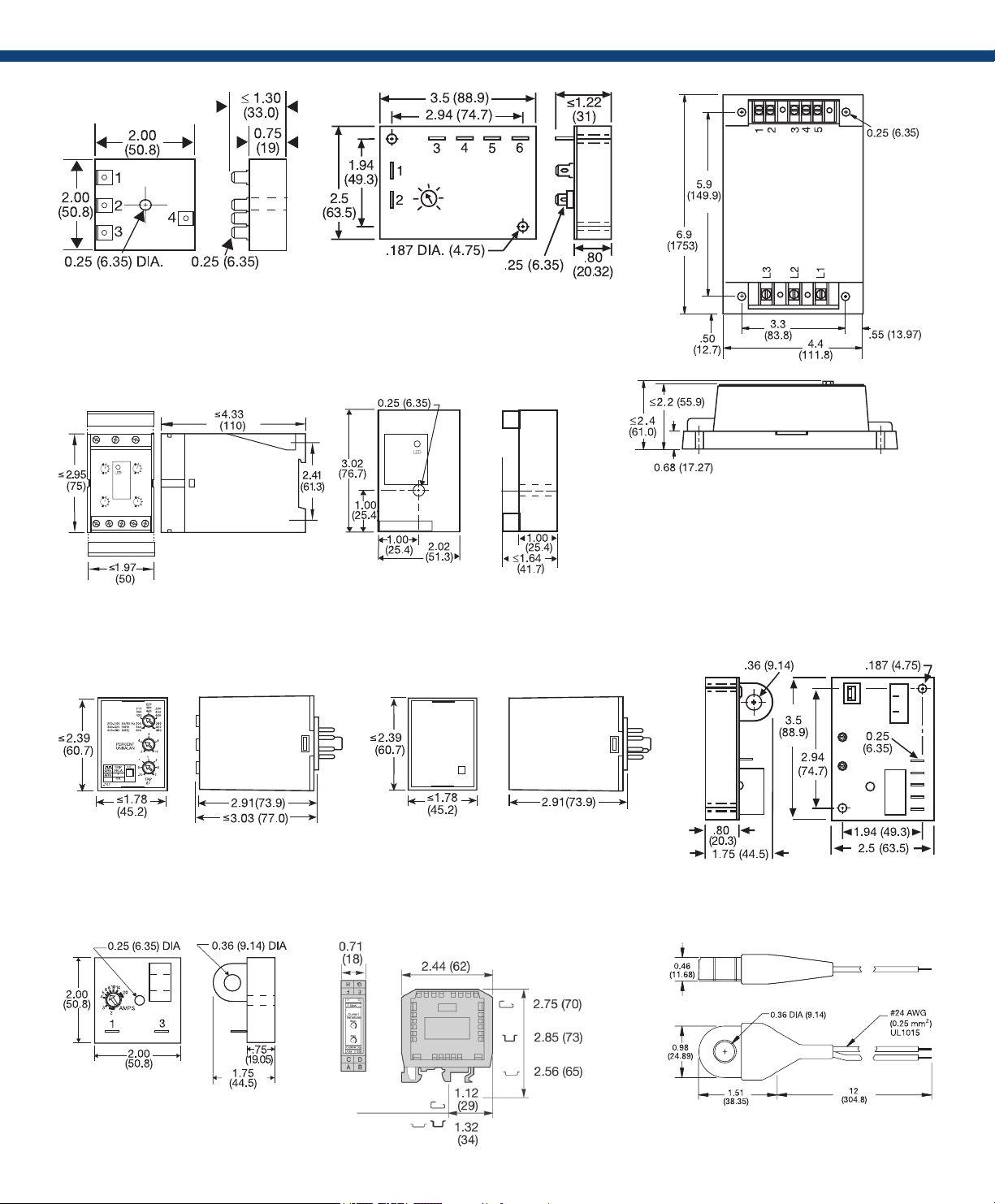
Appendix B - Dimensional Drawings
FIGURE 13 FIGURE 14 FIGURE 15
AF
SC3; SC4; SQ
FIGURE 16 FIGURE 17
RC
RC
DLMU
FIGURE 18
FB9L; HLMU; SCR9L
FIGURE 19
WVM
FIGURE 20
PLMU
FIGURE 21
TCS; TCSA
LLC4; LLC6; PLS
ECS; ECSW
FIGURE 22 FIGURE 23
LCS
DCSA
inches (millimeters)
(ECS has spade connectors and
ECSW has terminal board)
Page 3

Appendix C - Connection Diagrams
L1 N/L2
FIGURE 1 - FSU1000 Series
L1 N/L2
S1 = Optional low current switch
V = Voltage
L = Load
FIGURE 5 - FS300 Series
V = Voltage
L = Load
Note: Load may be in positive side.
FIGURE 2 - FS100 Series
L1 N
V = Voltage
L = Load
R = Red Wire
B = Black Wire
FIGURE 6 - FS400 Series
L1 N/L2
V = Voltage
L = Load
R = Red Wire
B = Black Wire
W= White Wire
FIGURE 3 - FS100 Series FIGURE 4 - FS200 Series
L1 N/L2
V = Voltage
V = Voltage
L = Load
FIGURE 7 - AF Series
L1 N/L2
V = Voltage
L = Load
L = Load
FIGURE 8 - FS500 Series
L1 N/L2
V = Voltage
FIGURE 11 - DLMU Series
FIGURE 9 - SC3/SC4 Series
SC4 shown;
for SC3, terminal 6 & load L4 are eliminated.
FIGURE 12 - HLMU Series
Note: Relay contacts are
isolated, 277VAC max.
L1, L2, L3 = Line Voltage Input
NO = Normally Open Contact
NC = Normally Closed Contact
C = Common, Transfer Contact
CAUTION: 2 amp max. fast acting fuses are
recommended to protect the equipment‘s
wiring. They are not required to protect the
HLMU.
FIGURE 10 - WVM Series
F = Fuses
NO = Normally Open
NC = Normally Closed
RS =
Optional Remote Reset Switch
Relay contacts are isolated.
CAUTION:
2 amp max fast acting fuses must
be installed externally in series
with each input. (3)
FIGURE 13 PLMU/PLM/PLR/PLS Series
F = Fuses
ØA = Phase A = L1
ØB = Phase B = L2
ØC = Phase C = L3
NO = Normally Open
NC = Normally Closed
2A fast acting fuses
recommended for safety (not
required)
Relay contacts are isolated.
!
L1, L2, L3 = Line Voltage Input
NO = Normally Open Contact
NC = Normally Closed Contact
C = Common, Transfer Contact
CAUTION: 2 amp max. fast acting
fuses are recommended to protect
the equipment‘s wiring. They are not
required to protect the DLMU.
! = Select alarm contact connection as N.O. or
N.C. when ordering; N.O. Shown.
FIGURE 14 TVM/TVW Series
L1 = Phase A
L2 = Phase B
L3 = Phase C
NO = Normally Open
NC = Normally Closed
C = Common, Transfer Contact
Relay contacts are isolated.
F = 2A Fast acting fuses are recommended,
but not required
 Loading...