

3 Phase V3 Phase V
3 Phase V
3 Phase V3 Phase V
oltage Monitoroltage Monitor
oltage Monitor
oltage Monitoroltage Monitor
PLR Series
Motor Protector
DescriptionDescription
Description
DescriptionDescription
The PLR Series provides a cost effective means of preventing 3 phase motor startup during adverse voltage
conditions. Proper A-B-C sequence must occur in order for the PLR's output contacts to energize. In addition,
the relay will not energize when an undervoltage or phase loss condition is present. The PLR protects a motor
against undervoltage operation. The adjustment knob sets the undervoltage trip point.
US Patent No. 6541954
ANSI Device # 27/32
Protects Against: Phase
Loss (On Startup), Phase
Reversal, Undervoltage
Used Where Moderate
Voltage Unbalance
Protection is Not Required
Direct Replacement for
Most Popular 3 Phase
Monitors
8 Pin Octal Base
Connection
SPDT Isolated 5 A Relay
Contacts
AMSE A17.1 rule 210.6
NEMA MG1 14:30, 14:35
IEEE C62.41-1991 Level B
Approvals:
AccessoriesAccessories
Accessories
AccessoriesAccessories
Panel mount kit
BZ1 BZ1
P/N:
BZ1
BZ1 BZ1
Octal
8-pin socket
OT08PC OT08PC
P/N:
OT08PC
OT08PC OT08PC
OperationOperation
Operation
OperationOperation
The output relay is energized and the LED glows when
all voltages are acceptable and the phase sequence
is correct. Undervoltage must be sensed for a
continuous dropout delay period before the relay deenergizes. Reset is automatic upon correction of the
fault condition. The output relay will not energize if a
fault condition is sensed as power is applied.
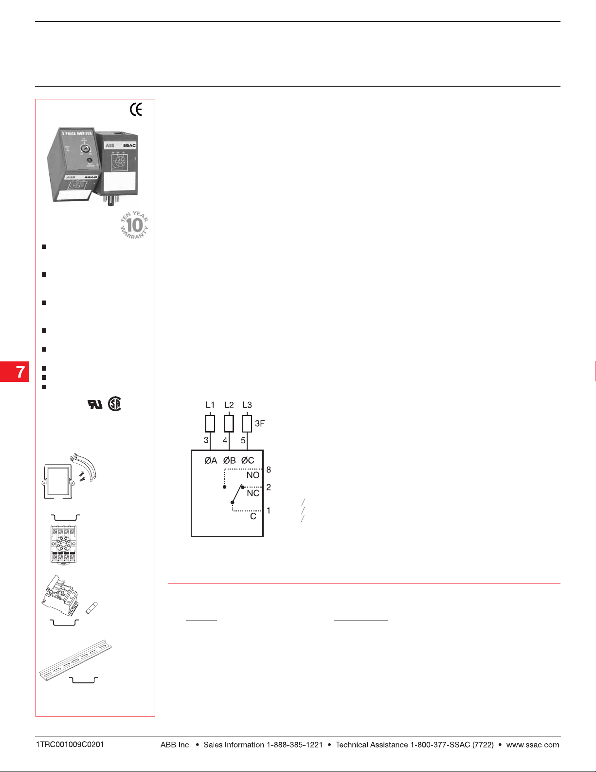
ConnectionConnection
Connection
ConnectionConnection
2 Amp
Fast Acting
Fuses
Recommended
For Safety
(Not Required)
F = Fuses
= Phase A = L1
OA
OB
= Phase B = L2
= Phase C = L3
OC
NO = Normally Open
NC = Normally Closed
Field Adjustment: Field Adjustment:
Field Adjustment:
Field Adjustment: Field Adjustment:
Turn the adjustment knob fully
counterclockwise and apply three-phase power.
The LED should be ON. Increase adjustment until
the LED goes OFF. Decrease adjustment until LED
glows again. If nuisance tripping occurs, decrease
the adjustment slightly.
NOTE:NOTE:
NOT E: When properly adjusted and operating in
NOTE:NOTE:
an average system, a voltage unbalance of 10% or
more is required for phase loss detection. When a
phase is lost while the motor is running, a voltage will
be induced into the open phase nearly equal in
magnitude to the normal phase-to-phase voltage.
This condition is known as regeneration. When
regenerated voltages are present, the voltage
unbalance during single phasing may not exceed
10% for some motors. The PLR Series may not
provide protection under this condition. For systems
that require superior phase loss protection, select
the PLMU Series.
3-phase fuse
block/disconnect
P0700-241 P0700-241
P/N:
P0700-241
P0700-241 P0700-241
2 AMP fuse
P0600-11P0600-11
P/N:
P0600-11
P0600-11P0600-11
DIN rail P/Ns:
017322005017322005
017322005 (St eel)
017322005017322005
C103PM C103PM
C103PM (Al)
C103PM C103PM
See accessory pages for
specifications.
Relay contacts are isolated. Dashed lines are
internal connections.
OrOr
dering Tdering T
Or
dering T
OrOr
dering Tdering T
VV
V
VV
oltageoltage
oltage
oltageoltage
ableable
able
ableable
95 ... 140 V AC
190 ... 270 V AC
340 ... 450 V AC
380 ... 500 V AC
Part NumberPart Number
Part Number
Part NumberPart Number
PLR120A
PLR240A
PLR380A
PLR480A
PLR02B01 06.07.04
Low Voltage Products & Systems7.22
3 Phase V3 Phase V
3 Phase V
3 Phase V3 Phase V
oltage Monitoroltage Monitor
oltage Monitor
oltage Monitoroltage Monitor
PLR Series
Motor Protector
Technical Data Technical Data
Technical Data
Technical Data Technical Data
Line VLine V
oltageoltage
Line V
oltage
Line VLine V
oltageoltage
Type 3 phase Delta or Wye with no connection to neutral
Frequency 50 ... 60 Hz
Phase Sequence ABC
Response TimesResponse Times
Response Times
Response TimesResponse Times
Pull-in ≤ 400 ms
Drop-out ≤ 100 ms
Hysterisis Pull-in/Drop-out ≅ 2%
OutputOutput
Output
OutputOutput
Type Electromechanical relay, energized when all voltages are acceptable
Form Single pole double throw (SPDT)
Rating 5 A resistive at 240 V AC: 1/4 Hp at 120 V AC
Maximum Voltage 250 V AC
ProtectionProtection
Protection
ProtectionProtection
Surge IEEE C62.41-1991 Level B
Isolation Voltage 120 & 240 V AC ≥ 1500 V RMS input to output
380 & 480 V AC ≥ 2500 V RMS input to output
MechanicalMechanical
Mechanical
MechanicalMechanical
Mounting Plug-in socket
Termination 8 pin, octal plug
EnvironmentalEnvironmental
Environmental
EnvironmentalEnvironmental
Operating Temperature 0°C ... +55°C
Storage Temperature -40°C ... +85°C
Weight ≅ 6 oz (170 g)
120 V AC 85 ... 130 V AC 143 V AC
240 V AC 170 ... 240 V AC 270 V AC
380 V AC 310 ... 410 V AC 480 V AC
480 V AC 350 ... 480 V AC 530 V AC
Nominal V Nominal V
Nominal V
Nominal V Nominal V
oltageoltage
Undervoltage Dropout Adjustment Range Undervoltage Dropout Adjustment Range
oltage
Undervoltage Dropout Adjustment Range
oltageoltage
Undervoltage Dropout Adjustment Range Undervoltage Dropout Adjustment Range
Line V Line V
Line V
Line V Line V
oltage oltage
oltage
oltage oltage
Max.Max.
Max.
Max.Max.
PLR02B01 06.07.04
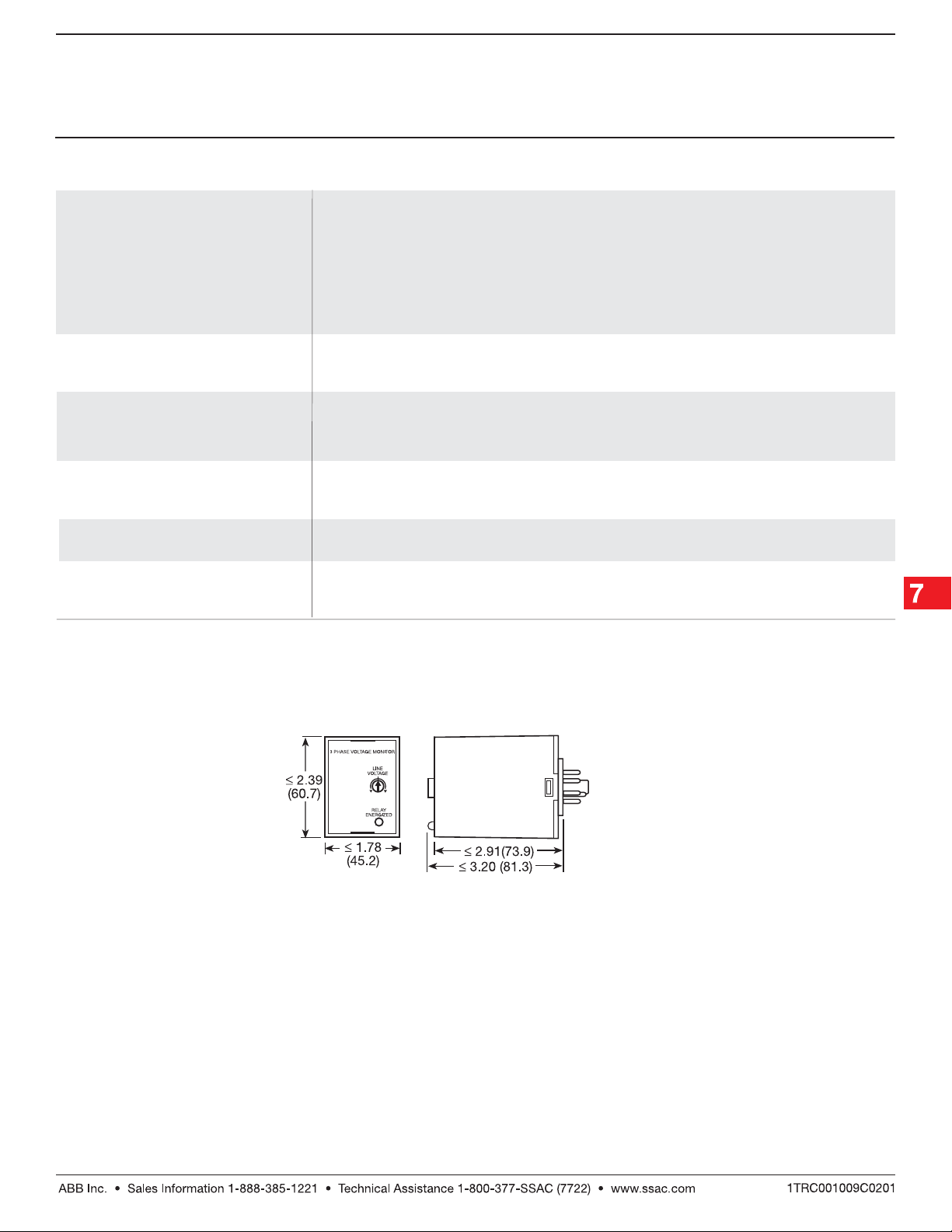
Mechanical View Mechanical View
Mechanical View
Mechanical View Mechanical View
Inches (Millimeters)
Low Voltage Products & Systems 7.23
 Loading...