

Page 1
3 Phase V3 Phase V
3 Phase V
3 Phase V3 Phase V
oltage Monitoroltage Monitor
oltage Monitor
oltage Monitoroltage Monitor
PLMU Series
Universal Plug-in Monitor
DescriptionDescription
Description
DescriptionDescription
The PLMU Series continuously measures the voltage of each of the three phases to provide protection for three
phase motors and sensitive loads. Its microcontroller senses under and over voltage, voltage unbalance,
phase loss, and phase reversal. Protection is provided even when regenerated voltages are present. Universal
voltage operation and standard base connection allows the PLMU to replace hundreds of competitive part
numbers.
ANSI Device #27/47/59
Protects Against: Phase
Loss, Phase Reversal,
Overvoltage, Undervoltage,
& Unbalanced Voltages
Octal Plug-in with SPDT
Isolated 10 A Contacts
Operates from 200 ... 480 V AC
LED Indicator Glows Green
when Voltages are
Acceptable, Red for Faults
Simple 3-Wire Connection for
Delta or Wye Systems
ASME A17.1 rule 210.6
NEMA MG1 14:30, 14:35
IEEE C62.41-1991 Level B
Approvals:
AccessoriesAccessories
Accessories
AccessoriesAccessories
Panel mount kit
BZ1 BZ1
P/N:
BZ1
BZ1 BZ1
OperationOperation
Operation
OperationOperation
Upon application of power, a 0.6 s random start delay
begins and the PLMU measures the voltage levels
and line frequency and selects the voltage range.
The output relay is energized and the LED glows green
when all voltages are acceptable and the phase
sequence is correct. LED flashes green during trip
delay, glows red when output de-energizes.
Undervoltage, overvoltage, and voltage unbalance
must be sensed for continuous trip delay before the
relay de-energizes. Re-energization is automatic upon
fault correction. The output relay will not energize if a
fault condition is sensed as three phase input voltage
is applied. Line voltage is selected with the knob,
setting the over and under voltage trip points. Voltage
range is automatically selected by the microcontroller.
ConnectionConnection
Connection
ConnectionConnection
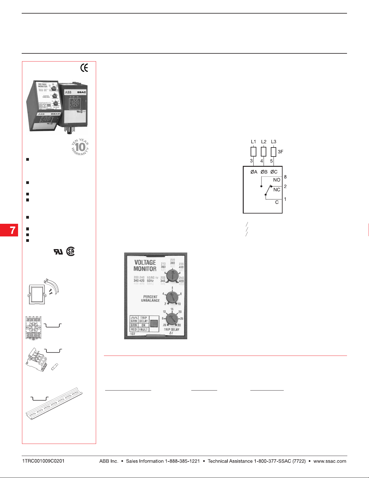
2 Amp
Fast Acting
Fuses
Recommended
For Safety
(Not Required)
F = Fuses
= Phase A = L1
OA
= Phase B = L2
OB
= Phase C = L3
OC
NO = Normally Open
NC = Normally Closed
Relay contacts are isolated. Dashed lines are
internal connections.
Octal 8 pin socket
OT08PCOT08PC
P/N:
OT08PC
OT08PCOT08PC
3-phase fuse
block/disconnect
P0700-241P0700-241
P/N:
P0700-241
P0700-241P0700-241
2 AMP fuse
P0600-11 P0600-11
P/N:
P0600-11
P0600-11 P0600-11
DIN rail P/Ns:
017322005 017322005
017322005 (Stee l)
017322005 017322005
C103PMC103PM
C103PM (Al )
C103PMC103PM
See accessory pages for
specifications.
Faceplate View
OrOr
dering Tdering T
Or
dering T
OrOr
dering Tdering T
VV
oltage Unbalanceoltage Unbalance
V
oltage Unbalance
VV
oltage Unbalanceoltage Unbalance
ableable
able
ableable
TT
rip Delayrip Delay
T
rip Delay
TT
rip Delayrip Delay
Adjustable 2 ... 10% PLMU11Adjustable 0.25 ... 30 s
Available with Fixed Unbalance and Trip Delay
Part NumberPart Number
Part Number
Part NumberPart Number
Low Voltage Products & Systems7.14
PLMU2B01 06.08.04
Page 2
3 Phase V3 Phase V
3 Phase V
3 Phase V3 Phase V
oltage Monitoroltage Monitor
oltage Monitor
oltage Monitoroltage Monitor
PLMU Series
Universal Plug-in Monitor
Technical Data Technical Data
Technical Data
Technical Data Technical Data
Line VLine V
oltageoltage
Line V
oltage
Line VLine V
oltageoltage
Type Three phase Delta or Wye with no connection to neutral
Line Voltage 200 ... 480 V AC +/-15%; 50 ... 60 Hz +/-2 Hz
Adjustable Voltage Ranges
(Automatic Range Selection) 200 ... 240 V AC, 50 ... 60 Hz
Maximum Voltage 552 V AC
Phase Sequence ABC
Overvoltage, Undervoltage, &Overvoltage, Undervoltage, &
Overvoltage, Undervoltage, &
Overvoltage, Undervoltage, &Overvoltage, Undervoltage, &
V V
oltage Unbalanceoltage Unbalance
V
oltage Unbalance
V V
oltage Unbalanceoltage Unbalance
Type
Overvoltage & Undervoltage
Undervoltage Trip Point 88 ... 92% of adjusted line voltage
Reset Voltage +2% of trip voltage
Overvoltage Trip Point 109 ... 113% of adjusted line voltage
Reset Voltage -2% of trip voltage
Voltage Unbalance Trip Point Adjustable from 2 ... 10% or fixed 4 ... 10%
Reset on Balance (%):
Selected Unbalance 2 3 4 5 6 7 8 9 10
Reset 1.5 2.5 3.5 4.5 5.4 6.3 7.2 8.1 9
TT
rip Delay Rangerip Delay Range
T
rip Delay Range
TT
rip Delay Rangerip Delay Range
Severe Unbalance - 2X Selected Unbalance 0.25 ... 2 s; disabled when the trip delay is less than 2 s
Random Start Delay ≅ 0.6 s
Phase Reversal & Phase Loss TPhase Reversal & Phase Loss T
Phase Reversal & Phase Loss T
Phase Reversal & Phase Loss TPhase Reversal & Phase Loss T
Phase Loss Set Point ≥ 15% unbalance
Reset Type Automatic
Output TOutput T
Output T
Output TOutput T
Rating 10 A resistive @ 240 V AC; 1/4 hp @ 125 V AC; 1/3 hp @ 250 V AC; max. voltage 277 V AC
Life Mechanical -- 1 x 10⁶ ; Electrical -- 1 x 10
ProtectionProtection
Protection
ProtectionProtection
Surge IEEE C62.41-1991 Level B
Isolation Voltage ≥ 2500 V RMS input to output
MechanicalMechanical
Mechanical
MechanicalMechanical
Mounting* Plug-in socket rated 600 V AC
Termination 8 Pin octal plug
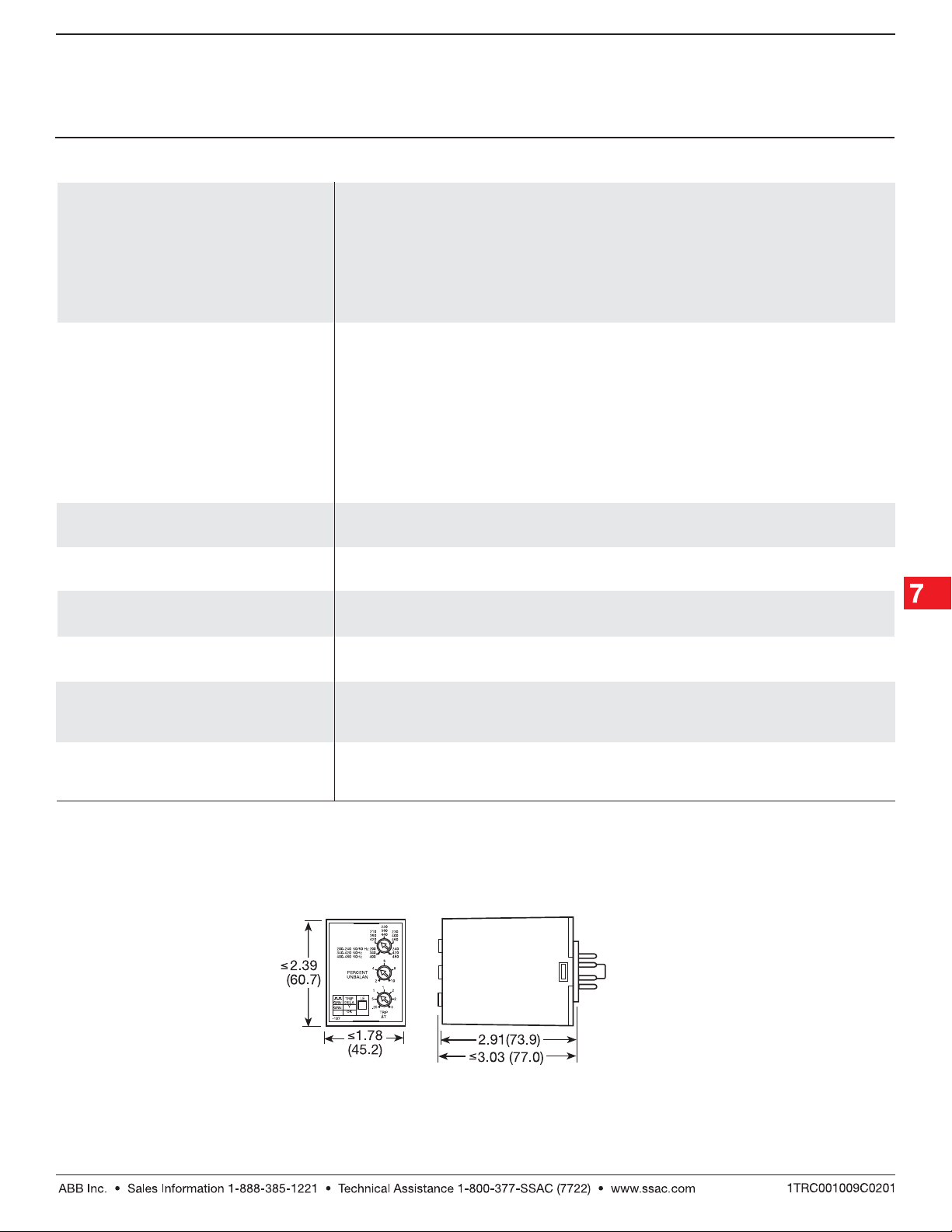
Package 3.03 x 2.39 x 1.78 in. (77.0 x 60.7 x 45.2 mm)
EnvironmentalEnvironmental
Environmental
EnvironmentalEnvironmental
Operating Temperature -40°C ... +60°C
Storage Temperature -40°C ... +85°C
Weight ≅ 8.6 oz (244 g)
ypeype
ype Energized when voltages are acceptable
ypeype
rip Timerip Time
rip Time ≤ 150 ms
rip Timerip Time
340 ... 420 V AC, 50 Hz
400 ... 480 V AC, 60 Hz
Voltage detection with delayed trip & automatic reset
Adj. from 0.25 ... 30 s or fixed 2 ... 30 s +/-15%
5
*CAUTION: Select an octal socket rated for
600 V AC operation.
Mechanical View Mechanical View
Mechanical View
Mechanical View Mechanical View
PLMU2B01 06.08.04
Inches (Millimeters)
Low Voltage Products & Systems 7.15
 Loading...