

SSAC ORS Series Catalog Page
Single Shot (Pulse Former)Single Shot (Pulse Former)
Single Shot (Pulse Former)
Single Shot (Pulse Former)Single Shot (Pulse Former)
ORS Series
Time Delay Relay
DescriptionDescription
Description
DescriptionDescription
The ORS Series open PCB construction offers the user good economy without sacrificing performance and
reliability. The output relay is available in isolated 10 A double pole double throw or single pole double throw
forms. The time delay may be ordered as factory fixed, onboard knob, or external adjustment. All connections
are 0.25 in. (6.35 mm) male quick connect terminals.
Low Cost Open PCB
Construction
Momentary or Maintained
Initiation
10 A DPDT or SPDT Relay
Contacts
Delays From 50 ms ... 300 s
in 5 Ranges
+/-2% Repeat Accuracy
+/-10% Factory Calibration
Approvals:
AccessoriesAccessories
Accessories
AccessoriesAccessories
BB
B
BB
External adjust
potentiometer
AA
A
AA
P/Ns:
P1004-12 P1004-12
P1004-12 (fig A)
P1004-12 P1004-12
P1004-12-X P1004-12-X
P1004-12-X (fig B)
P1004-12-X P1004-12-X
Female quick
connect
P/N:
P1015-64 P1015-64
P1015-64
P1015-64 P1015-64
(AWG 14/16)
OperationOperation
Operation
OperationOperation
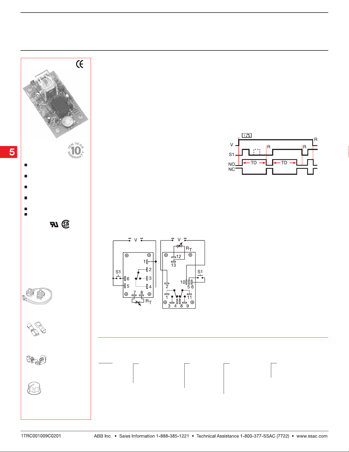
Input voltage must be applied before and during
timing. Upon momentary or maintained closure of the
initiate switch (leading edge triggered), the output relay
energizes for a measured interval of time. At the end
of the time delay, the output de-energizes. Opening
or reclosing the initiate switch during timing has no
affect on the time delay . The output will ener gize if the
initiate switch is closed when input voltage is applied.
Reset:Reset:
Reset: Reset occurs when the time delay is complete
Reset:Reset:
and the initiate switch is opened. Loss of input voltage
resets the time delay and output.
ConnectionConnection
Connection
ConnectionConnection
SPDT
DPDT
Relay contacts are isolated. Dashed lines
are internal connections.
RT is used when external adjustment is ordered.
FunctionFunction
Function
FunctionFunction
Single Shot
V = Voltage S1 = Initiate Switch
TD = Time Delay R = Reset
NO = Normally Open NC = Normally Closed
Quick connect to
screw adaptor
P1015-18 P1015-18
P/N:
P1015-18
P1015-18 P1015-18
Versa-knob
P0700-7 P0700-7
P/N:
P0700-7
P0700-7 P0700-7
See accessory pages for
specifications.
OrOr
dering Tdering T
Or
dering T
OrOr
dering Tdering T
ORS ORS
ORS
ORS ORS
SeriesSeries
Series
SeriesSeries
Example P/N:Example P/N:
Example P/N:
Example P/N:Example P/N:
ableable
able
ableable
X X
X
X X
InputInput
Input
InputInput
24A 24A
–
24A - 24 V AC
24A 24A
120A 120A
–
120A - 120 V AC
120A 120A
230A 230A
–
230A - 230 V AC
230A 230A
ORS120A21 ORS120A21
ORS120A21 Fixed –
ORS120A21 ORS120A21
X X
X
X X
AdjustmentAdjustment
Adjustment
AdjustmentAdjustment
11
–
1 - Fixed
11
2 2
–
2 - Adj. on
2 2
Unit
33
–
3 - External
33
Adjust
ORS120A1200DORS120A1200D
ORS120A1200D
ORS120A1200DORS120A1200D
X X
X
X X
Time DelayTime Delay
Time Delay *
Time DelayTime Delay
11
–
1 - 0.05 ... 3 s
11
22
–
2 - 0.5 ... 30 s
22
33
–
3 - 0.6 ... 60 s
33
44
–
4 - 1.2 ... 120 s
44
55
–
5 - 3.0 ... 300 s
55
*If Fixed Delay is selected, insert
delay [
X X
X
X X
Blank - SPDT
–
0.050.05
0.05...
0.050.05
Low Voltage Products & Systems5.106
Output FormOutput Form
Output Form
Output FormOutput Form
DD
D - DPDT
DD
300300
300] in seconds.
300300
ORS02B01 07.02.04
Single Shot (Pulse Former)Single Shot (Pulse Former)
Single Shot (Pulse Former)
Single Shot (Pulse Former)Single Shot (Pulse Former)
ORS Series
Time Delay Relay
Technical Data Technical Data
Technical Data
Technical Data Technical Data
Time DelayTime Delay
Time Delay
Time DelayTime Delay
Type Analog circuitry
Range 0.05 ... 300 s in 5 adjustable ranges or fixed
Repeat Accuracy +/-2% or 20 ms, whichever is greater
Tolerance (Factory Calibration) Adjustable: Guaranteed range
Reset Time ≤ 50 ms
Initiate Time ≤ 70 ms
Time Delay vs. Temperature & Voltage ≤ +/-10%
InputInput
Input
InputInput
Voltage 24, 120, or 230 V AC
Tolerance 24 V AC -15% ... +20%
120 & 230 V AC -20% ... +10%
Line Frequency 50 ... 60 Hz
Power Consumption 2.25 W
OutputOutput
Output
OutputOutput
Type Electromechanical relay
Form Isolated SPDT or DPDT
Rating 10 A resistive at 120/240 V AC & 28 V DC; 1/3 hp at 120/240 V AC
Life Mechanical--1x10⁷; Electrical--1x10
ProtectionProtection
Protection
ProtectionProtection
Isolation Voltage ≥1500 V RMS input to output
MechanicalMechanical
Mechanical
MechanicalMechanical
Mounting Surface mount with four #6 (M3.5 x 0.6) screws
Termination 0.25 in. (6.35 mm) male quick connect terminals
EnvironmentalEnvironmental
Environmental
EnvironmentalEnvironmental
Operating Temperature -20°C ... +65°C
Storage Temperature -30°C ... +85°C
Weight ≅ 2.7 oz (77 g)
Fixed: +/-10%
6
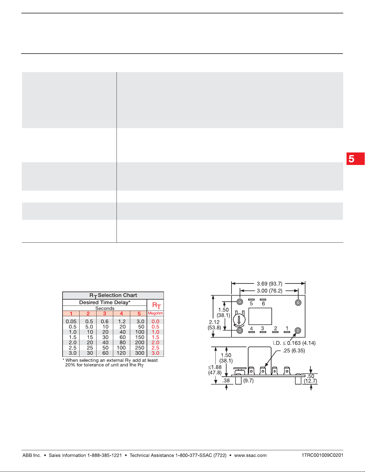
Mechanical View Mechanical View
Mechanical View
Mechanical View Mechanical View
ORS02B01 07.02.04
Note: SPDT shown. DPDT is the same size.
Terminal location is different.
Low Voltage Products & Systems 5.107
Inches (Millimeters)
 Loading...