

Page 1
Protection Relays
Pump Controls and Liquid Level Controls
LLC8 SERIES
Low Level Cutoff Liquid Level Controls
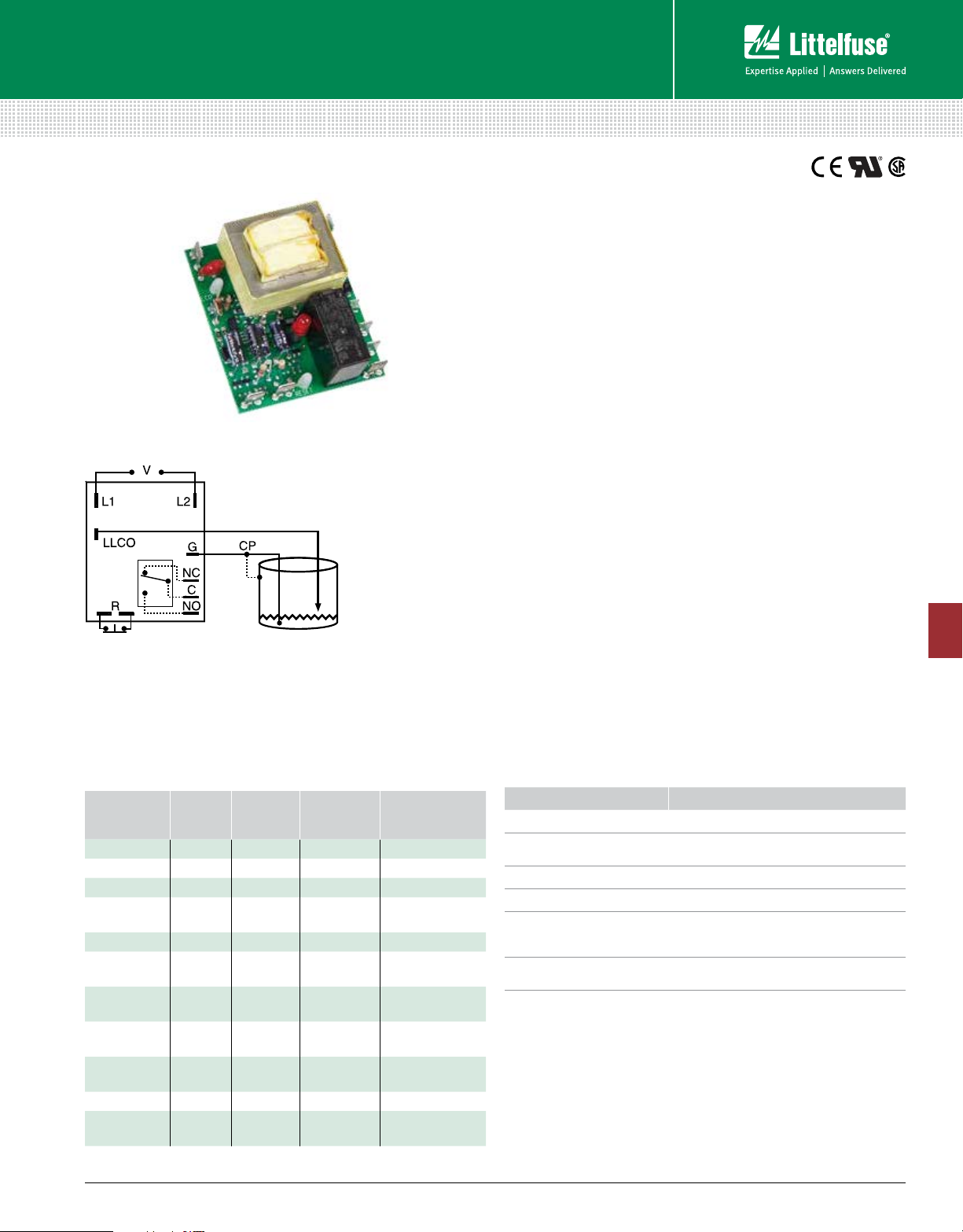
Wiring Diagram
V = Voltage
LLCO = Low Level
Probe
G, CP = Ground or
Common
(Reference)
Probe
R = Optional NC
Reset Switch
(not included)
NO = Normally Open
Metal Tank or use
additional Probe
Relay contacts are isolated. Connect common to conductive tank. Additional probe is
necessary for non-conductive or insulated tanks.
For dimensional drawing see: Appendix, page 514, Figure 42.
NC = Normally Closed
C = Common or
Transfer Contact
Description
The LLC8 Series is a low cost, single-probe conductive liquid
level control designed for low liquid level cutoff protection. It
offers a factory fixed time delay of 1 - 60s and is available for
input voltages of 24, 120, or 230VAC. LED indicator illuminates
whenever the LLC8’s isolated, 10A, SPDT output relay is
energized. Sense resistance is fixed from 5K - 250KΩ. Available
with manual/automatic reset or a special manual reset with a
power outage feature that auto resets the unit when power is
restored and the water level is acceptable. 24 and 120VAC units
are UL recognized as limit switches under UL353 (230VAC units
are UL 508) and CSA certified under Standard 14.
Operation
Automatic Reset (Reset switch not connected): When liquid
rises to low level cutoff probe, output relay and LED indicator
energize. When liquid falls below the low level cutoff probe,
the output relay and LED indicator de-energize after a fixed
time delay.
Manual Reset (Reset switch connected): When the liquid
level falls below low level probe, the output relay and LED
de-energize after a fixed time delay. When the liquid level rises
to low level probe, the output relay and LED indicator remain
de-energized until the NC manual reset switch is opened; then
they energize immediately.
Power Outage Manual Reset (Reset switch connected):
A power outage causes the output relay and LED indicator to
de-energize. Upon restoration of power, if the liquid is touching
the low level probe, the output relay and LED indicator will
re-energize. If the liquid level is below the low level probe, the
output relay and LED indicator remain de-energized until the NC
reset switch is opened.
8
PUMP CONTROLS & LIQUID LEVEL CONTROLS
Ordering Information
MODEL
INPUT
VOLTAGE
LLC825F5M 24VAC 5s 5kΩ Manual/automatic
LLC842F103M 120VAC 2s 10kΩ Manual/automatic
LLC843F10M 120VAC 3s 10kΩ Manual/automatic
LLC843F10P 120VAC 3s 10kΩ
LLC843F26M 120VAC 3s 26kΩ Manual/automatic
LLC843F26P 120VAC 3s 26kΩ
LLC845F25P 120VAC 5s 25kΩ
LLC8430F250P 120VAC 30s 250kΩ
LLC8430F26P 120VAC 30s 26kΩ
LLC8610F12M 230VAC 10s 12kΩ Manual/automatic
LLC863F26P 230VAC 3s 26kΩ
©2017 Littelfuse Protection Relays & Controls
TIME
DELAY
(FIXED)
SENSE
RESISTANCE
RESET
Power outage
manual reset
Power outage
manual reset
Power outage
manual reset
Power outage
manual reset
Power outage
manual reset
Power outage
manual reset
Features & Benefits
FEATURES BENEFITS
Isolated 12VAC probes Prevents scale buildup on probe
Open PCB design
Conformally coated PCB Protects against moisture and corrosion
LED indication Visual indication output relay is energized
Power outage protection
(see ordering table
for models)
24VAC & 120VAC models
meet UL353
151
Cost effective design for OEM low liquid level
cutoff protection
Automatically resets the unit when power is
restored and the water level is acceptable
Required for use as a low level limit switch
LLC8
 Loading...