

SSAC LLC6 Series Data Sheet
Liquid level
controls
Low Level Cutoff
LLC6 Series
Liquid Level Control
Description
The LLC6 Series is a plug-in single probe conductive liquid level control designed for low liquid level cutoff
protection. It offers a factory xed time delay of 1 to 60 s and is available in input voltages of 24, 120, or
230 V AC. LED indicator illuminates whenever the LLC6’s 10 A SPDT output relay is energized. Available
with automatic/manual reset or a special manual reset with power outage feature, which auto resets the unit
when power is restored and the water level is acceptable. 24 V AC and 120 V AC units are recognized as
limit switches under UL353 (230 V AC units are UL508) and CSA certied under Standard 14.
Designed for Low Level
Cutoff Protection
Energized on Wet Probe
Fixed Time Delay of 1 ... 60 s
Sense Resistance of
5K ... 250K Ω
24, 120, or 230 V AC
Input Voltage Available
10 A, SPDT Relay Contacts
Approvals:
Accessories
Panel mount kit
P/N: BZ1
Operation
Automatic Reset
(Reset terminals not connected):
When liquid rises to the low level cutoff probe, the
output relay and the LED indicator energize. When
the liquid falls below low level cutoff probe, the output
relay and the LED indicator de-energize after a xed
time delay.
Manual Reset (Reset switch connected): When the
liquid level falls below the low level probe, the output
relay and LED de-energize after a xed time delay.
When the liquid level rises to the low level probe, the
output relay and LED indicator remain de-energized
until the manual reset switch is opened; then they
energize immediately.
Power Outage Manual Reset (Reset switch
connected): A power outage causes the output relay
and LED indicator to de-energize. Upon restoration of
power, if the liquid level is above the low level probe,
the output relay and LED indicator will re-energize. If
the liquid level is below the low level probe, the output
relay and LED indicator remain de-energized until the
Normally Closed (NC) reset switch is opened.
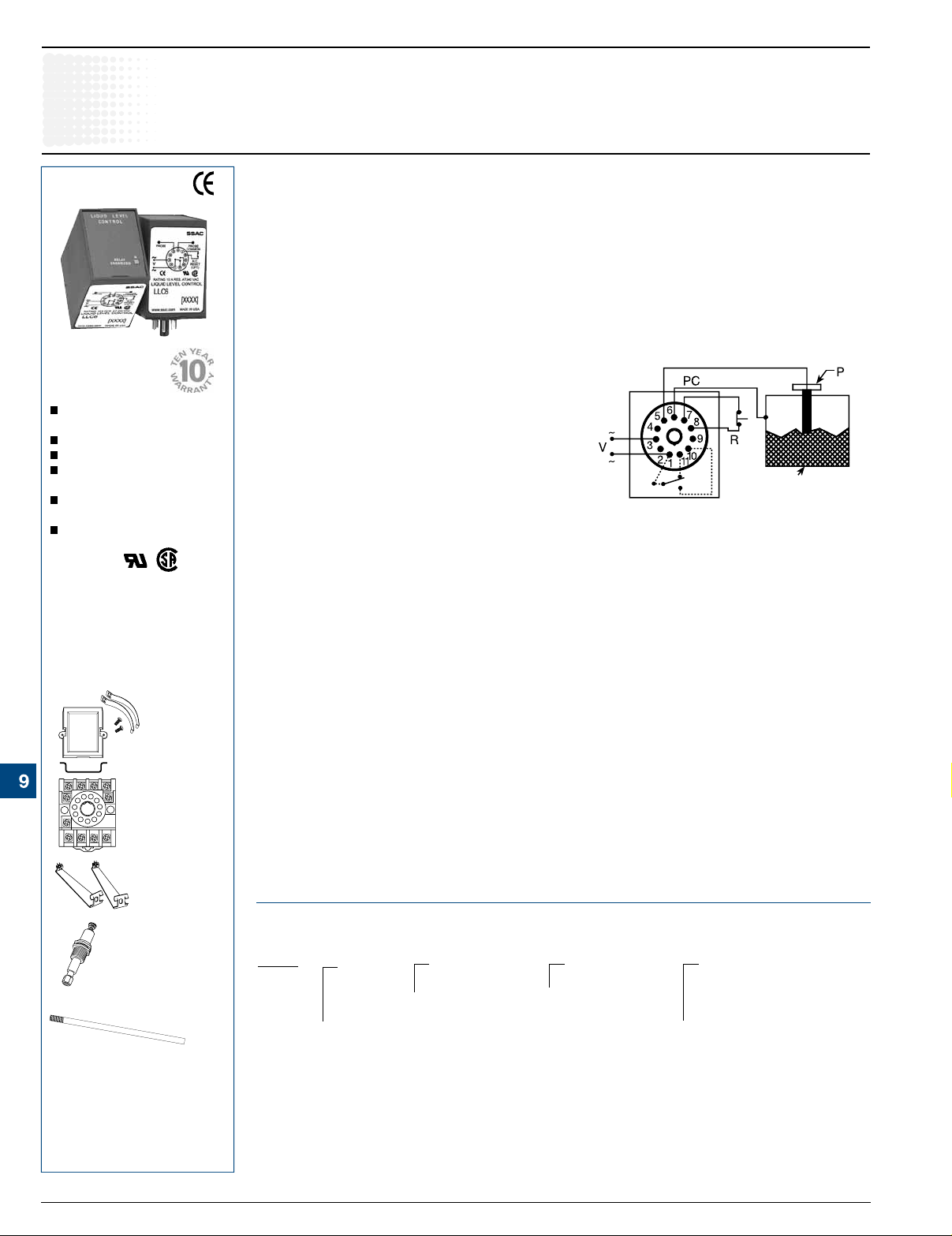
Connection
Metal Tank or Use
Second Probe
Dashed lines are internal connections.
Connect common to conductive tank. Additional
probe is necessary for non-conductive or
insulated tanks.
PC = Probe Common P = Probe V = Voltage
R = Optional NC Reset Switch
11-pin socket
P/N: NDS-11
Available Models-
Hold down clips
P/N: PSC11
LLC6610F5P
Don’t see what you need? Call us for a minimum quantity and price quote!
Ordering Table
Electrode
P/N: PHST-38QTN
Level probe
P/N: LLP-24
See accessory pages for
specications.
9.10
SSAC, LLC. • 800-377-7722 • customerservice@ssac.com • technicalsupport@ssac.com • www.ssac.com
• denotes a preferred product
LLC6
Series
–2 - 24 V AC
–4 - 120 V AC
–6 - 230 V AC
Example P/N:
X
Input
LLC6410F25M, LLC6640F100P
X
–Specify Fixed Delay
In Seconds
[1 ... 60]
In 1 s Increments
X
Sense ResistanceTime Delay (Fixed)
- Fixed
–F
Specify Fixed
Resistance
In Kilohms
[5 ... 250]
In 1 K increments
X
Reset
–M - Manual/Automatic
Reset
–P - Power Outage
Manual Reset
LLC62B01 09.10
 Loading...